Abstract
In this article, the definition of weight functions of a light shield at the intersection of the bullet in different field areas of shield registration is considered. The signal definition at the input of an optical sensor at the intersection of the bullet of a light shield is viewed. The research results can be used in considering the facts that can influence on the error estimation of the coordinate determination when a bullet hits the target.
Highlights
- A light shield consists from an illuminator and an optical sensor located on opposite sides from the sheaf of trajectories of the bullets has a finite width.
- Within the registration area a weight function of a light shield can have a form close to rectangle, trapezium and triangular.
- The kind of a signal, entering the input of an optical sensor, is determined by the convolution of a weight function of a light shield and the bullet shadow.
- The results we obtain can be used during the consideration than can influence on the error estimation of the determination of coordinates when a bullet hits the target.
1. Introduction
An information-measuring system (IMS) for small arms measuring contains an indestructible light target built with the application of light shields. The shields of a light target are placed at different angles concerning a plane registration (a paper target). A light shield consists from an illuminator and an optical sensor located on opposite sides from the sheaf of trajectories of the bullets. An optical sensor includes an amplifier-filter and a photo detector. An optical sensor sets the moment of the intersection of the bullet of light shield. A light target is used for the evaluation of the coordinates and . The error estimation of the coordinate measurement depends on the error estimation of time measurement of flight of the bullet screens. In the article, weight functions of a light shield and the signal at the input of an optical sensor are considered.
2. Weight functions of light shield
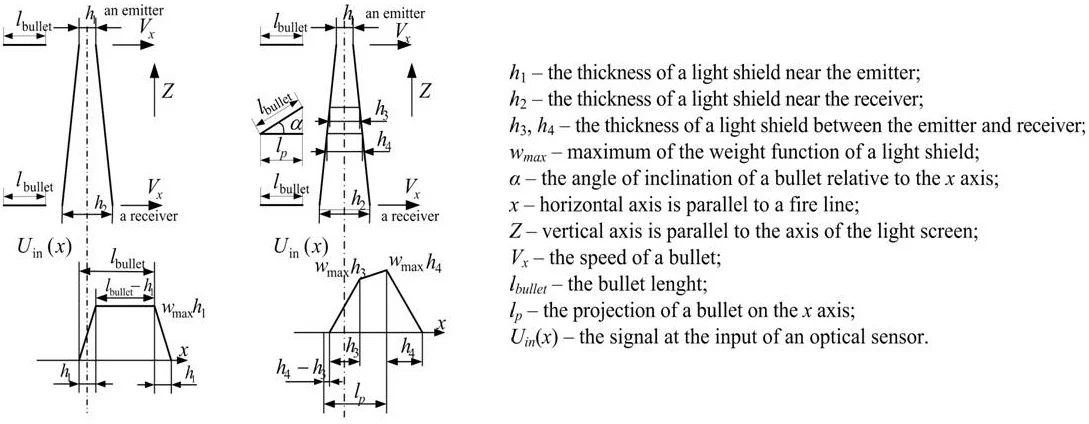
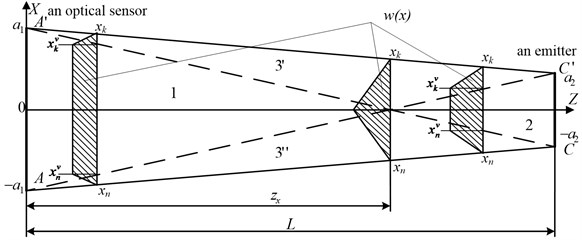
To determinate the time of the bullet flight through a light shield, light shields with the work on a negative contrast are used [1]. In the Fig. 1 these is the scheme of a light shield with slit diaphragms from the side of the light source and the receiver side [2]. The axis is horizontal, the axis is vertical and the axis is parallel to a fire line. In the projection of a light shield on the plane the registration area of the bullet flight places in the area of high values and one can consider that the value of shielded energy in this sector changes abruptly.
For the scheme of a light shield, these designations are accepted:
– coordinate system related to slit receiver ;
– coordinate system related to slit emitter ;
– coordinates of the elementary platform of the bullet in the coordinate system of the receiver;
2×2 – the size of slit diaphragm of the receiver;
2×2 – the size of slit diaphragm of the emitter;
– straight line connecting the point of the element with the elements and on slit diaphragms;
– the angle between the axis and a straight line .
– the distance from the slit diaphragm of the receiver before slit diaphragm of the emitter .
– the distance from the slit diaphragm of the receiver before the element .
Fig. 1The scheme of a light shield with slit light source and receiver
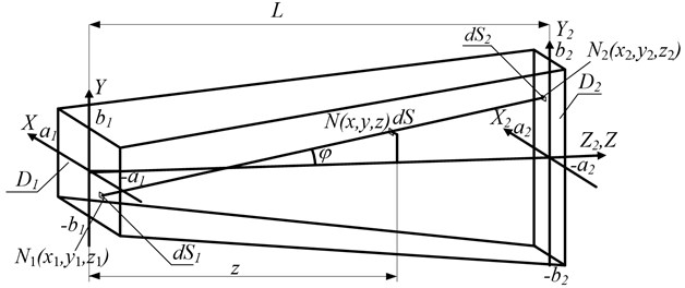
The length of the slit diaphragm of the receiver 2 is significantly smaller than the slit diaphragm of the emitter 2 and the distance .
Now we introduce the definition of the weight function of a light shield. For this purpose, we consider a point signal from a point emission source. The position of the point emission source can be set using angular coordinates shown in the Fig. 2, where – the angle of rotation around the axis , – the angle of rotation around the axis , or for small angles practically around the axis , – the point emission source, – the straight line from the origin coordinate to the point emission source .
We present a point signal in the form of spatial delta-function [3-6]:
where , – the brightness of the emitter, – the delta-function, , – the initial values of the angle of rotation.
The delta-function satisfies the normalization condition:
and has filter characteristics:
The projections of the point (Fig. 2) on the coordinate system for small angles , can be written as:
i.e. for a fixed distance of the point from the beginning of the coordinates under instead of angular coordinates of the point we can view its Cartesian coordinates.
Then instead (1) we get a spatial -function:
The response of the system to -function is its weight function. Under the weight function we understand the change of the energy flow on the photo detector due to exposure of a point source or an elementary platform that is parallel to the platform of the photo detector. The arguments of a weight function we consider (Fig. 2) the position coordinates of a point source or an elementary platform with the area in a light plane, coinciding with the plane , and coordinate movement of source or platforms along the normal to a light plane.
In case , where – speed movement along the normal to a light plane, – time, we go to a weight function, as a function of time.
We consider the dependence of the quality of shielded energy at the intersection of the bullets of a light shield for value series of a vertical coordinate . For this purpose in the Fig. 3 the projection of a light shield on the plane is demonstrated. We consider that the length of the bullet is enough for the overlap of the thickness of a locking plane with the work on a negative contrast.
Fig. 2Angular coordinates of the position of emission source A
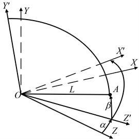
Fig. 3Areas of a light shield in the plane YOZ
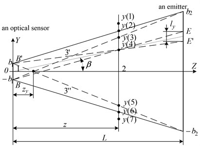
In the Fig. 3 lines , ; –, ; , – and –, – divide a light shield into the areas 1, 2, 3, moreover the area 3 consists of symmetric areas 3' and 3". The point, separating 1, 2, has a coordinate:
Since , then , then the length of the area 1 is small and it is near the site of the receiver. The registration area of the bullet flight, based on test requirements, has to be big enough along the axes and . In practice, the registration area never puts in the area 1 on the plane . So, weight functions of a light shield in the plane are considered only for sufficiently large values of the coordinate , relating to the areas 2 and 3.
Then the value of shielded energy is proportional to the length of the segment . Based on similarity of triangles in the area 2, we find the length of the segment by the formula:
where – the length of the projection of the segment on the line of the emitter, – the distance from the receiver to the emitter, – the lateral coordinate of the bullet hit in a light shield.
Now we find the value of light flow of shielded energy in the area 2 by the formula [7, 8]:
where – the brightness of the emitter:
For small values of the angle , can be equal to one.
Under the condition of the full bullet overlap of a light flow on the axis , the width of the platforms and determines the width of the diaphragms 2 and 2 correspondingly.
Then:
The dependence of on determines the dependence of on (Eq. (9)). The dependence of on determines the dependence of on (Eq. (7)).
For small values of the angle , can be equal to one, . Then the value of the shielded emission is:
Then the value of shielded energy weakly depends on the value of a vertical coordinate of the bullet.
We consider the definition of weight functions of a light shield in the case when a bullet hits different areas of the shield. For this purpose, we take the projection of a light shield on the plane (Fig. 4). A light shield is divided into four areas: 1, 2, 3', 3" and at the same time all the areas are working ones.
A weight function of the shield, when the bullet moves along the axis parallel to fire line in the area 1 (Fig. 4), has the form of the trapezium and is determined by the formula:
where:
for .
Fig. 4The projection of a light shield on the axis XOZ. w(x) – weight function of a light shield
At the intersection of the bullets of the area 2 (Fig. 4) a weight function of the shield has the form of the trapezium and is determined by the formula:
where , , а , , and are determined by the Eq. (14)-(17).
At the intersection of the bullets of the area, when (Fig. 4) a weight function of a light shield has a triangular form and is determined by the Eq. (19):
where , are determined by the Eq. (5), (8) for .
From the analysis of weight functions we have that the value does not depend on the coordinate in the area 1 and has a quadratic dependence in the area 2. The expansion of the area 1 can be reached by the increase due to increase and/or decrease .
3. The signal definition at the input of optical sensor
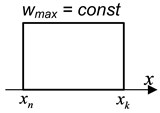
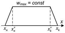
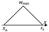
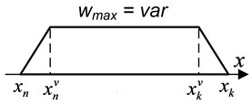
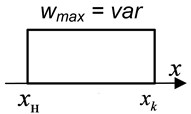
As a result of the analysis, weight functions of a light shield can have a following form (Fig. 5):
a) A weight function of a rectangular form with a constant value that does not depend on the coordinates of the bullet flight (Fig. 5(a)).
b) A weight function in the form of a trapezium with a constant value that does not depend on the coordinates of the bullet flight (Fig. 5(b)).
c) A weight function of a triangular form (Fig. 5(c)).
d) A weight function in the form of a trapezium with a constant value that does not depend on the coordinates of the bullet flight (Fig. 5(d)).
e) A weight function of a rectangular form with a constant value that does not depend on the coordinates of the bullet flight (Fig. 5(e)).
We get the bullet with a small diameter value that we can omit compared with a bullet length and sizes of registration area of a light shield.
Fig. 5Weight functions of light shields
a)
b)
c)
d)
e)
The signal at the input of an optical sensor is the result of the convolution of a weight function of a light shield with the value of the bullet projection to normal to a light plane , received from the part of the bullet length and entered in the plane by the formula:
In the case of an infinitely thin light shield (a shield can be presented in the form of a plane (Fig. 6(а)), the signal at the input of an optical sensor (Fig. 6(c)) is determined by the Eq. (21):
where:
where – the bullet length, is determined by the Eq. (13).
The signal has a rectangular form.
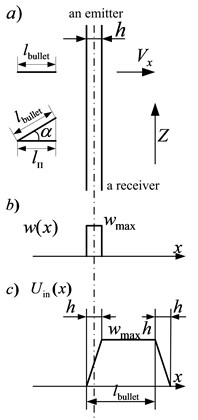
In the case of a light shied when we cannot neglect its thickness as compared to the bullet length (Fig. 7(а)), the signal at the input of an optical sensor (Fig. 7(c)) is determined by the formula:
where , – the thickness of a light shield, is determined by the Eq. (13).
A weight function of a light shield is rectangular. The signal at the input of an optical sensor has the form of a trapezium.
Fig. 6The signal at the input of a sensor with a thin blocking plane
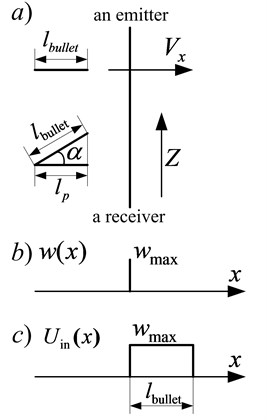
Fig. 7The signal at the input of a sensor with a rectangular weight function of a light shield of constant final thickness
In the case when the thickness of a light shield depends on the coordinate (Fig. 8(а)), a weight function of a light shield has a rectangular form (Fig. 8(b)). A bullet moves along the normal to a middle line of a blocking plane. The signal at the input of an optical sensor has the form of a trapezium (Fig. 8(d)). A signal duration changes when changes according to a shield thickness , that is determined by the formula:
where , , .
In the case when the thickness of a light shield depends on the coordinate when the bullet moves under the angle (Fig. 9(а)), a weight function of a light shield has a rectangular form (Fig. 9(b)). The signal at the input of an optical sensor is divided into three linearly varying parts (Fig. 9(а)) by the formula:
In the case when the bullet length is smaller than the thickness of a blocking plane, a signal level, entering the input of an optical sensor, decreases.
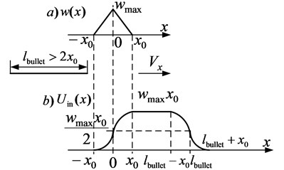
In the case of weight functions presented in the Fig. 5(b)-5(d), the dependence of an optical sensor from the coordinate is determined by a quadratic equation [9] and the pattern of change from is nonlinear.
For example, for the case, when a weight function of a light shield has the form demonstrated in the Fig. 5(c) when , an input signal will have the following form (Fig. 10(b)) when the signal level, entering the input of an optical sensor, will look like this:
Fig. 8The signal at the input of a sensor with a rectangular weight function for a shield with thickness, that is dependent from z
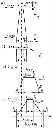
Fig. 9The signal at the input of a sensor with a rectangular weight function for a light shield with thickness, that is dependent from z when the bullet moves under the angle α to the horizontal
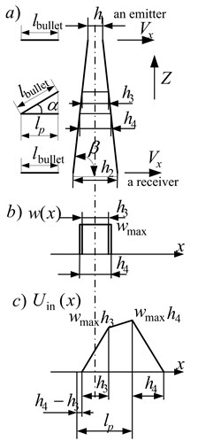
Fig. 10The signal at the input of an optical sensor for a weight function (Fig. 5(c)) of a light shield
4. Results
Alight shield has a finite width. The width of a light shield depends on the length of the emitter, the length of a sensitive area of an optical sensor, the width of the diaphragm of the emitter and an optical sensor. Within the registration area a weight function of a light shield can have a form close to rectangle, trapezium and triangular.
The kind of a signal, entering the input of an optical sensor, is determined by the convolution of a weight function of a light shield and the bullet shadow. The bullet shadow is the function of change of light flow at the intersection of the bullets of light shield.
For a thin bullet, when we can neglect its diameter, the kind of a signal at the input of the sensor depends on maximum energy, blocked by a bullet at the intersection of a light shield; the thickness of the shield; the law of change of the shield thickness as a function of the distance to the emitter (receiver) and the angle of the intersection of the bullets of this shield.
In the case of a rectangle weight function signal fronts have a linear character. For a trapezium weight function, the fronts of an energy signal at the input of the sensor has a parabolic form with a smooth signal change at the beginning and at the end of the formation of the front and recession. This signal form substantially complicates the evaluation of the starting and final positions of a signal in any situations when you can hear noise.
For the evaluation of a valid signal at the input of an optical sensor, it is necessary to take into consideration a bullet shadow both on the normal to a light shield and to a light shield. As a whole, a signal at the input of an optical sensor is determined by the set of parameters. They are the angle of nutation and the procession of the bullet, the angle of the course and the pitch shot, coordinates of the intersection of the bullets of a blocking plane , , , angles of inclination of blocking planes, the size and form of the bullet shadow. The connection between listed angular parameters is determined by nonlinear equations. The equations that define a bullet shadow are also nonlinear. Weight functions of light shields depend on the coordinates. In a general sense, the equations of convolution of weight functions with a bullet shadow should be considered as parametric.
5. Conclusions
We suppose that the results we obtain can be used during the consideration than can influence on the error estimation of the determination of time moment at the intersection of the bullets of light shield and on the error estimation of the determination of coordinates when a bullet hits the target.
References
-
Aphanasiev V. A., Lyalin V. E. Optoelectronic transformer of a light shield. Synergy of Sciences, Vol. 25, 2018, p. 686-697.
-
Optoelectronic Blocking Device for the Registration of the Moment of the Intersection of the Bullets of Light Shield of the Target. Patent 2386100, Russian Federation, IPC F41J5/00, 2008.
-
Besekersky N. А., Popov E. P. Theory of Systems of Automatic Control. Science, Moscow, 1974, p. 720.
-
Ephimov M. V. Tracking Systems with Optical Connections. Energy, Moscow, 1969, p. 184.
-
Kazakov V. S., Aphanasiev V. A., Aphanasieva N. U. Theory of Automatic Control. Continuous and Pulse Systems, Statistical Dynamics of Linear Systems. P.1.: Educational Manual. Publishing IzhSTU, Izhevsk, 2007, p. 307.
-
Porphiriev Ph. L. Theory of Optoelectronic Devices and Systems. Mechanical Engineering, 1980, p. 272.
-
Begunov B. N., Zakaznov N. P. Theory of Optical Systems. Mechanical Engineering, Moscow, p. 1973-488.
-
Pavlov A. V. Optoelectronic Device (Fundamentals of Theory and Calculation). Energy, Moscow, 1971, p. 359.
-
Yetter Edward W., Conner Harry G. Method and Apparatus for Determining the Coordinate of a Projectile by Measuring the Time Interval Between the Interception of Successive Light Screens. Patent USA No. 3487226, 250-222, 1967.
-
Sergienko A. B. Digital Processing of Signals. 3rd Edition. Saint-Petersburg, 2011, p. 768.
-
Zhou C.-X., Li Y.-J., Wu J.-H., Zhou H.-C. Measuring system of velocity and impact point coordinate of projectiles, 2008.
-
Tang X.-R., Zhang R., Yu D.-S., Sun Y.-Q. Experimental testing technique of small fragments with light screens. Chinese Journal of High Pressure Physics, Vol. 28, Issue 1, 2014, p. 103-107.
-
Yu J.-Y., Li Y.-X., Wang X.-M. Measurement of impact points using reflective light screen target of single column light source. Optics and Precision Engineering, Vol. 18, Issue 6, 2010, p. 1354-1360.
-
Liu J., Li Y.-J., Zhao D.-E., Zhou H.-C. Optoelectronic detection system for projectile impact location measurement based on rectangular laser screen. Journal of Optoelectronics Laser, Vol. 22, Issue 5, 2011, p. 748-752.
About this article

