Abstract
In the modern mortar radio fuze, the use of turbine generators as the power source for fuzes is very common. The ballistic air pressure during the flight of the projectiles is used as the driving force to drive the turbine motor. In this paper, the turbine motor signal is parameterized in combination with the actual situation, and the idea of using the hardware to simulate the turbine power generation is proposed. The generation of the turbine motor signal is simulated by means of simulation software. Design the circuit to verify the simulation results, and have a certain reference for how to easily detect the fuze in the mass production process.
1. Introduction
As a fortified weapon of infantry, single-soldier rocket has the characteristics of light weight, short range, convenient carrying and low price. It is very suitable for some local conflict situations. It is equipped with air-blast fuze with high-precision explosion point control. It has developed from the simple target of killing vital point to the target of killing vital surface. It can detonate over or on the side of the target, greatly improving the single-soldier missile. Operational effectiveness and destructive power of military rockets [1].
Before the air-blast fuze of rocket projectile is put into use, it is necessary to simulate the flight process of the projectile, and comprehensively detect the parameters of the fuze, such as release time, firing time and speed. Traditionally, the signal generator is used to simulate the speed measurement signal, the battery is used to simulate the power supply of the turbine motor, and the switch is used to simulate the projectile launching [2]. The whole process is complicated and unreliable. It takes a lot of time to detect a set of fuzes. In the mass production process, in order to improve the detection efficiency, it is necessary to optimize the speed measurement circuit and turbine motor analog circuit, and design a set of detection system. This paper focuses on the turbine motor analog circuit.
2. Overall design
2.1. Types and generation principles of signals
Using electronic circuit technology to generate the turbine motor analog model needed for testing, first of all, it is necessary to understand the signal type of the turbine motor. The signal needed to be simulated in this paper is alternating sine wave signal formed by generator rotor rotating in stator and cutting magnetic induction line. Its motion model is shown in Fig. 1 [3].
According to the basic theory of electromagnetic field, the sinusoidal wave signal generated by the rotor cutting the magnetic induction line. Turbine rotor rotates under the driving of air pressure. The faster the speed of rotation, the higher the frequency and amplitude of the sinusoidal wave signal [5]. The form of the sinusoidal wave signal is shown in Fig. 2.
Combining with the practical application background of this paper, the velocity of projectile’s muzzle is about 300 m/s, and the target is damaged in the range of 2 km. In the course of the projectile’s flight, the turbine analog signal we need is about 9 V, and the frequency is 4-9 kHz sinusoidal wave signal [6].
Fig. 1Stator cut magnetic induction line
Fig. 2Sinusoidal signal form
3. Design of analog signal scheme for turbine motor
3.1. Composition of turbine motor analog circuit
The analog circuit of turbine motor is composed of power supply, sine wave generating circuit, sine wave generating power supply circuit and sine wave amplifying circuit. Its structure is shown in Fig. 3. The power supply is supplied by sinusoidal wave power supply circuit for sinusoidal wave generator and amplifier circuit. The signal generated by sinusoidal wave generator circuit is generated by amplifier circuit for turbine analog signal.
Fig. 3Turbine signal analog circuit structure

3.2. Sinusoidal generation power supply circuit
The principle of sine wave generation power supply circuit is shown in Fig. 4.
Fig. 4Sinusoidal generation power supply circuit
Using the DC/DC conversion of A0515D-2WR2 chip, the capacitance of C1, C2 and C4 is 0.1 uF, and that of C2 is 10 uF. The DC voltage of 5 V is input. After passing through A0515D-2WR2 chip, the output voltage of ±15 V is supplied for sinusoidal wave generating circuit and amplifying circuit.
3.3. Sine wave generating circuit
ICL8038 is a precise oscillating integrated circuit with multiple waveform outputs. It can output low distortion sine wave, triangle wave, rectangular wave and other pulse signals ranging from 0.001 Hz to 300 kHz [4]. ICL8038 chip is chosen as the source of signal, and three precise potentiometers are used to adjust the resistance of the peripheral circuit. The chip is powered by a single power supply of +10 V ~ +30 V or a double power supply of ±5 V ~ ±15 V. ICL8038 chip consists of two comparators, two buffers, a trigger and a sine wave converter. The threshold voltages of the two voltage comparators are 2/3Vcc and 1/3Vcc respectively. The constant current source inside the chip is used to charge and discharge the connected capacitors to generate triangular wave, which is converted into sinusoidal wave by sinusoidal wave converter and output from the two pins. By adjusting the parameters of external components, the charging and discharging time of capacitors can be changed, the output waveform can be selected, the frequency and duty cycle of the waveform can be changed, and the sine wave signal needed can be easily output. The principle of sine wave circuit is shown in Fig. 5.
Fig. 5Sinusoidal wave generating circuit
3.4. Sinusoidal amplifier circuit
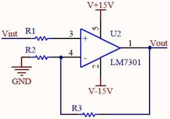
The principle of the amplifier is shown in Fig. 6. LM7301 Low-Power Operational amplifier is selected. The power supply is ±15 V. The signal is input from the same input terminal of the operational amplifier through resistance . The reverse input terminal of the operational amplifier is grounded and the output signal is Vout. According to the characteristics of integrated operational amplifier, it can be obtained from virtual short and virtual break:
In conjunction with the above equation, we can obtain:
By choosing the appropriate feedback resistance, the amplification factor of the circuit can be determined, and the desired analog signal of the turbine motor can be obtained.
Fig. 6Sinusoidal amplifier circuit
4. Simulation
4.1. Sinusoidal amplifier circuit simulation
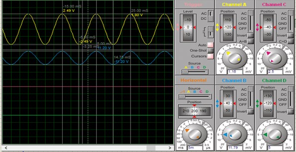
According to the design, the circuit is simulated by Proteus simulation software. The input signal of the amplifier circuit is sinusoidal wave signal with amplitude of 2.5 V. After the operation amplifier LM7301, a sinusoidal wave signal with the same frequency and amplitude of 11.2 V is output on the virtual oscilloscope. The simulation results are shown in the following Fig. 7 and Fig. 8.
The gain calculated by simulation is 4.48, which is consistent with the result calculated by design.
Fig. 7Principle diagram of amplifier circuit simulation

Fig. 8Amplification circuit simulation
4.2. Sinusoidal amplifier circuit simulation
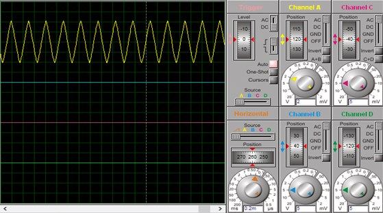
Proteus is used to draw the peripheral circuit of ICL8038. As shown in Fig. 9, when the resistance of potentiometers RV1, RV2 and RV3 is adjusted and the resistance of potentiometers is different, sinusoidal waves of different frequencies and amplitudes can be displayed on the virtual oscilloscope. The simulation results are shown in Fig. 10 and meet the design requirements.
Fig. 9Simulating schematic diagram of sinusoidal wave generator circuit

Fig. 10Simulated sinusoidal waveform
5. Experimental verification
According to the design scheme of hardware circuit, the circuit is made and tested (as shown in Fig. 11). The oscilloscope is used to collect the waveform of the circuit (as shown in Fig. 12). The waveform is 4.2 V in amplitude and 6 kHz in frequency. The signal is stable and has less distortion.
Fig. 11Experimental test
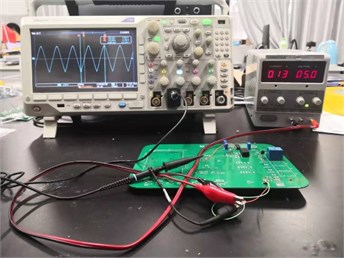
Fig. 12Signal waveform
6. Conclusions
In this paper, the turbine signal analog circuit of fuze detection system is designed, and the simulation of turbine motor signal is realized by pure hardware. The frequency and amplitude of the turbine analog signal can be adjusted conveniently by using the internal circuit of the integrated function generator ICL8038 chip. The generated signal can meet the needs of detection. The application in the fuze detection system can significantly improve the efficiency of production.
References
-
Lu Mingyang, Li Haojie, Li Changsheng, et al. Design of rocket fuze detection system based on DSC. Modern Electronic Technology, Vol. 11, 2016.
-
Deng Yaoqian Mortar velocity characteristics and turbine generator output. Journal of Detection and Control, Vol. 31, Issue 1, 2009, p. 49-52.
-
Song Chengtian, Wang Keyong, Zheng Chain, et al. forced bomb fuze turbine generator analog signal generator design. Instrumentation Journal, Vol. 29, Issue 3, 2008, p. 614-617.
-
Xiao Chen, Chen Jianxiang Design of an arbitrary waveform signal generator. Procedia Engineering, Vol. 15, 2011, p. 2500-2504.
-
Ren Da Lu, Wang Li Turbine generator speed test system design. Shanxi Electronic Technology, Vol. 1, 2015, p. 13-14.
-
Ahmar E. A., Choqueuse V., Benbouzid M. E. H., et al. Advanced signal processing techniques for fault detection and diagnosis in a wind turbine induction generator drive train: a comparative study. IEEE Energy Conversion Congress and Exposition, 2010.
About this article

This work was supported in part by the National Natural Science Foundation of China (Grant No. 61403201), in part by the Advanced Research Project of the 13th Five-Year Plan (Grant No. 41419050104), in part by the Six Talent Peak Projects (KTHY-019), and in part by the National Key Laboratory Foundation (Grant No. 6142601180101).
