Abstract
Theoretical justification for the choice of the strain-resistant element location on the loom of the canoe paddle in order to register the power parameters of interaction of an athlete with the paddle in natural conditions of rowing locomotions is presented in the article. Taking into account the introduced simplifications, a classical task of calculating the materials resistance from which the loom of the paddle is manufactured is submitted. The obtained result is reliable and allows with sufficient degree of accuracy to determine mechanical stresses arising in the process of rowing in location of measuring devices – tensometers, which provides registration of objective indices characterizing power of forces applied by an athlete in the support (water) part of a stroke. Besides, based on the MEMS-sensors readings, mathematical calculation of forces applied to the paddle in the process of rowing was made, which in specified conditions allows to estimate regularities of values ratio of the recorded dynamic parameters.
1. Introduction
Modern elite sport is characterized by constantly increasing competition and athletic performance. The problem of athletes training process improvement becomes more and more urgent. One of the key tasks of any athlete is maximum realization of the competitive potential, the performance of which is inseparably linked with the quality of the training process. Innovative technologies are of increasing importance in the race for the result, application of which allows to identify individual features of an athlete, to track the dynamics of his/her preparation, to detect the mechanisms of interaction of various biomechanical parameters of motor actions in the structure of elements performance of the main competitive exercise [1-5]. However, the applicability of introduced technological innovations is determined by the recorded data, which must meet certain conditions [2]:
– reliability and validity;
– significance in the structure of a competitive exercise;
– convenience and processing speed.
Reliability and validity of the received data is ensured by the selected principles and registration technologies. Their significance is determined on the basis of systematic and complex analysis of the competitive exercise structure, as well as the opinions of the relevant specialists. Convenience and processing speed depend primarily on the schematic features of measuring devices and systems, as well as optimization level of mathematical registration algorithms and initial signal processing. An essential condition for such means application is their compactness, small weight, and wireless work autonomy, so as not to affect ergonomic properties of the athlete-boat–paddle system. It is possible to meet these requirements employing MEMS technology [6, 7].
Preparedness of an athlete is characterized, as a rule, by physiological, physical, and technical indices [8]. Existing methods and tools for physiological and physical parameters evaluation and control are standardized and mostly universal, allowing them to be used in different sports. Evaluation of technical preparedness of athletes is carried out at performance of the main competitive exercise in conditions of natural control medium, which demand corresponding requirements to measuring instruments. In particular, the main feature of rowing as a sport is to carry out training and competitive activities at the junction of the air and aquatic environment, which significantly impede collection of the necessary information [9].
It is worth noting a positive trend of technical support of the training process of rowers through development and introduction of various information and measurement systems and computer technologies. In recent decades, intensive research activities have led to a clear understanding of the biomechanical process of rowing, as well as principle approaches to data recording and evaluation [10]. Measurement of the key kinematic parameters (duration and average speed of control segments and competitive distance covering, rowing rate, the run, time ratio of support and non-support phases, etc.) can now be automated by interfacing high-speed video filming, inertial measurement systems and GPS-based devices (Global Positioning System), as well as specialized software products and computational algorithms of digital processing and analysis of recorded signals [11-13]. Improvement of the training process of rowers can be carried out based on the data of rowing technique simulation, which will allow to identify the fundamental factors ensuring performance efficiency of motor actions of an athlete, describe their interaction at change of different parameters (change of the material composition and paddle design to alter its resonance characteristics, design of the boat bottom in order to increase its stability and specific speed, etc.) [14-19]. However, determination of the dynamic structure of rowing locomotions in the natural control medium is still not a fully solved task. In the field of rowlock rowing (academic rowing), several most successful examples of hardware and software complexes and devices for recording and evaluating both kinematic and dynamic parameters of rowing technique can be highlighted: PowerLine, SmartOar, BioRowTel System, as well as Oar Power Meter (WEBA Sport). Success of the considered devices implementation and use can be explained by the motor stereotype of rowing academicians, which is restricted by the design characteristics of the boat. In particular, the athlete's seat moves along the slides, and the paddle is fixed by means of a rowlock creating an additional point of support limiting the amplitude and degree of freedom of its movement. Non-rowlock rowing is characterized by absence of relative fixation of athlete’s body units actively involved in rowing, as well as fixed points of paddle support. This creates additional difficulties in developing measuring devices as well as computational algorithms. In order to determine dynamic characteristics of a stroke, the method of tensometry and piezometry was repeatedly used [20, 21]. Significant disadvantages of the systems designed on the basis of these technologies are their large size, multi-element, as well as lack of mechanisms and algorithms of primary processing of the recorded data. Combination of these factors prevents introduction of such complexes into practice of athletes training. Nevertheless, the success of the studies carried out has assigned these methods, especially tensometry, the status of the most informative and reliable. However, questions remain regarding the quality of the results obtained and the validity of the measurements.
2. Determination of the position of the strain gauge elements
Tensometric method of investigation of power interaction of an athlete with the water surface by means of a paddle in the cycle of rowing locomotions is based on the use of tensoresistive elements as a part of measuring systems and devices. Due to the design and schematic features of the resistive strain sensors connection to the electrical circuit, the recorded data are proportional to the value of the equipment deformation, in this case – the loom of the paddle. Since the paddle deforms along the entire length depending on the forces applied and the location of the support points, we have suggested that there is a problem of choosing the location of the tensoresistive element. Besides, the location of the resistive strain sensor, due to calibration of the device has no effect on absolute indices, but has a significant impact on its resolution capability. This is due to the phenomenon of elongation of the upper layer of the material caused by deformation of the loom of the paddle. Maximum elongation is located in the zone of maximum mechanical stress (1, 2) [23]:
where – normal stress in the cross section, Pa/m; – elongation of the material; – first-order modulus of elasticity (Young’s modulus), Pa, and:
where – the length of the oar shaft in the the non-load state, m; – absolute elongation of the oar shaft in condition of external effort exposure, m.
Thus, it can be stated with certainty that the correct positioning of the tensoresistive element on the equipment in terms of maximum local mechanical stress, all other things being equal (position of the support points, magnitude and direction of external forces, oar trajectory, etc.), will allow to register a higher quality data set characterizing the paddle deformation subjected to even minor forces.
Since in the process of rowing in natural conditions it is extremely difficult to record the effort distributed along the paddle due to the differential nature of the applied forces, we decided to perform calculation in conditions modeling the application of forces at the moment of the normal position of the paddle relative to the water surface (Fig. 1).
Fig. 1The paddle model during the calibration process
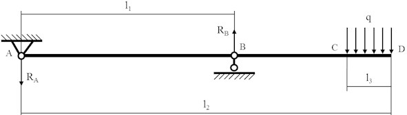
In the considered condition of non-load state, we neglect the own weight of the paddle, which results in no deformation. Location of the point A corresponds to the grip placement of the push arm, the point B corresponds to the pulling arm of the rower. The CD section corresponds to the region of the paddle blade interaction with the water surface, the area of which, in most cases, is 65-100 % of the blade area.
First, it is necessary to define the shear forces and bending moments at reference points A and B according to the three-moment Eqs. (3-6) [24]:
where – the resultant moment acting at point A, N·m; – support reaction in the center of the athlete’s pulling hand area (point B), N; – distance from the cross-section center of the paddle handle to the center of the athlete's pulling hand area, m; – length of the paddle, m; – the length within which the calibration load is acting, m; – distributed calibration load, N/m; and
where – the resultant moment acting at point B, N·m; and
Continuation of calculations to determine the shear forces, bending moments and mechanical stress distributed along the length of the paddle requires checking of the obtained equations according to the equilibrium condition of vertical components Eqs. (7, 8):
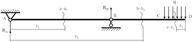
In order to determine the shear forces, bending moments and mechanical stress, which occur at application of load on the blade of the paddle (section CD) and distributed along its length, it is necessary to single out cross sections in the corresponding segments and perform calculations according to their location (Fig. 2).
Fig. 2Selection of cross-sections on the paddle during the calibration process: a–a1 – cross-section in the AB segment of the paddle; b–b1 – cross-section in the BC segment of the paddle; c–c1 – cross-section in the CD segment of the paddle
Consider the AB segment with the cross-section Eqs. (9, 10):
where – the distance from the center of the cross-section of the paddle handle to the cross-section , m; and
Consider the BC segment with the cross-section Eqs. (11, 12):
where – the distance from the center of the cross-section of the paddle handle to the cross-section , m; and
Consider the CD segment with the cross-section Eqs. (13, 14):
where – the distance from the blade edge to the cross-section , m; and
The general view of the diagrams of the shear forces and bending moments at the reference points of the designated segments, arising from the application of the distributed load in the CD segment, is shown in Fig. 3.
Fig. 3Diagrams of the shear forces and bending moments effecting the paddle during the calibration process
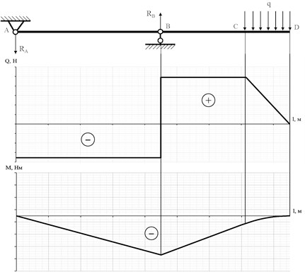
In this case, we are more interested in the mechanical stress caused by the bending of the loom of the paddle. Since we tend in general to describe the stress distribution under the external load that would characterize most of the existing canoe rowing paddles, and do not limit ourselves to the absolute values of the above-mentioned parameters, we neglect the specific cross-sectional shape of the loom on the grounds that it is basically constant (typically it is either a thin-walled cylinder, a thin-walled oval, or a thin-walled triangle), as well as the magnitude of its variations from the handle to the blade. The value of the mechanical stress, in this case, depends solely on the magnitude and variation of bending moments, and the corresponding diagram on the segment of the paddle duplicate the diagram of the bending moments Eq. (15) [24]:
where – maximum normal tension in the cross-section, Pa/m; – bending moment at point , N·m; – axial bending moment of resistance at, m3.
The axial moment of resistance depends on the shape and geometric dimensions of the cross-section.
It is worth noting that the diagram of the bending moments at point A is not actually zero. The moment at the point under consideration becomes zero only in case of free rotation of the paddle relative to the push arm, around the axis passing through the handle. In practice, however, an athlete deliberately limits the mobility of the paddle at point A in order to create a potential for a more effective pushing of the water surface in the support part of the stroke. The value of the bending moment in this point is in direct proportion to the effort of an athlete, which contributes to limitation of the paddle mobility (Fig. 4).
Fig. 4Precise definition of the bending moment acting in the area of the paddle handle depending on the degree of its mobility limitation
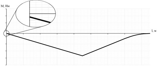
Complete limitation of the paddle mobility at the point in question corresponding to the fixed sealing will contribute to creation a maximum bending moment relative to the reaction force of the support . We believe that one of the reserves for improving the efficiency and performance of the competitive distance passing in canoe rowing may be hidden in this phenomenon.
According to the calculations carried out and the above-listed, there is ground to state that the most favorable location of the tensometric element in terms of completeness and quality of the recorded data is in the area near the pulling hand of the rower, and closer to the push hand, because, as already revealed, the diagram of the bending moments, and accordingly the mechanical stress at point A does not start from the zero position. The more forcefully the athlete limits the rotational motion of the paddle, the greater mechanical stress occurs at the segment of the paddle in question and, as a consequence, at the point in question. In the process of rowing the point of support B, corresponding to the center of the grip area of the athlete’s pulling hand, can be displaced by a distance of up to 100 mm, thus showing the error of about 2-3 %, which does not have a significant impact on the final result. On the basis of the above, we have found that for the vast majority of the paddles the most advantageous arrangement of the tensometric element is a 2/3 distance of the length of the segment from the handle to the center of the grip area of the athlete’s pulling hand.
3. Calculation of the forces applied to the oar
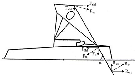
Devices, systems, hardware complexes of power parameters registration, designed on the basis of the tensoresistive elements, according to deformation principles allow to determine the set of forces applied to the oar. However, for a better analysis of technique of the exercise performed, it is often necessary to determine the magnitudes of the forces acting on the oar or apparatus separately from each other. We believe that in canoe rowing in the cycle of rowing locomotions it is possible to distinguish three main forces of influence on a paddle applied by the athlete and the control medium (Fig. 5).
We consider the process of canoeing in the sagittal plane due to the structural features of the measuring device used, the sensitive area of which is the wall of the cylinder truncated relative to the longitudinal axis. The radius of rounding of the sensitive area corresponds to the radius of the outer surface of the paddle loom for canoeing. Such a design allows the normal forces applied to the paddle during rowing to be recorded. In other words, projections of the spatial vectors of the applied to the paddle external forces on the plane under consideration.
Based on the above, in the cycle of rowing locomotions, when the support part of the stroke is made, we accept the direction of the resultant force vector , generated by the pulling hand of the athlete, as well as the reaction force of the water when the support part of the stroke is made, perpendicular to the position of the paddle. The resultant force vector produced by the athlete's push arm at the beginning of the support part of the stroke will be deflected from the horizontal position due to the presence of the vertical component , which is due to submersion of the paddle blade (‘blade down’). However, we believe that the direction of the vector in question will then tend to be horizontal, since the main function of the push arm of the rower, which provides for the accelerated advance of the athlete–paddle–boat system, is to create a reliable support point relative to which the paddle rotates. Thus, the main vector in the area of the push arm, actively effecting the paddle during the support part of the stroke and creating deformation in the plane of the system motion, is the force , which we take into account in the proposed mathematical calculation of isolated forces in canoe rowing on the basis of the readings of the tensodynamographic sensor. It is worth noting that the presented calculation is valid only within the established by us limits relative to force vectors and orientation Eqs. (16-19):
Fig. 5Forces and their directions of impact on the paddle in the cycle of rowing locomotions: Fuh – the push hand force (upper hand); Flh – the pulling hand force (lower hand); Rw – the water support reaction
The resultant action on the paddle under the conditions in question can be determined based on the rules of vector addition Eq. (20):
The solution of the equation given is made relative to unknown for the moment of interest. Calculation can be greatly simplified using specialized computing software.
The proposed mathematical calculation makes it possible to determine the ratio of forces applied on the paddle by the athlete and control medium, combined action of which creates propulsive effect on the system “athlete-paddle-boat”, contributing to its accelerated propulsion. Reliability of relative values obtained by means of the considered calculation is confirmed by the principle of registration of the peddle loom deformation in the process of rowing, as well as by geometric features of the sensitive area of the tensodynamographic sensor used by us. This shape of the sensor allows the maximum values of the paddle deformation in the plane of the system motion to be recorded. Any deviation of the paddle from the specified plane in the process of rowing will lead to decrease in the values of the recorded indicators. It is also worth noting, that most of the strokes are carried out either in the plane set by us or in an extremely close to it, since the performance of such strokes can ensure the straightness of the boat movement.
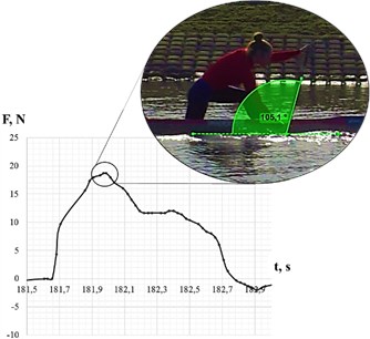
As part of the pilot study, we conducted an experiment to determine the ratio of external forces applied to the paddle by means of fixing a MEMS sensor (smart tensometric sensor) to the paddle and carrying out synchronous planar video shooting. The recording frequency of the video camera and of the sensor are identical (60 Hz) (Fig. 6).
According to the initial data (sensor readings 18.66 kg, angle of inclination of the paddle to the water surface 105, 1°) we have established the following relative ratio of forces: – 27.37 %, – 49.61 %, – 23.02 %. Besides, the given ratio during the support part of the stroke in the cycle will change slightly (within 5 %). The established phenomenon makes it possible to state that the main force applied to the paddle in the process of rowing is the force of the pulling hand of the athlete, the value of which is half of the forces acting on the paddle in total.
Obtaining integer and significantly more accurate indices of the athlete’s force effect and of the control medium on the paddle requires consideration of the rotational movement of the paddle in three-dimensional space, because in fact the force vectors are not strictly located in the same plane due to the physiological structure of human joints interacting with the paddle.
Fig. 6Correlation of the area of the tensodynamogram curve with the paddle orientation in the process of rowing
4. Conclusions
The effectiveness of competitive activities depends directly on the quality of the training process, which manifests itself in various aspects. In particular, one of the most important prerequisite for training efficiency in modern highly competitive conditions is determination and consideration of individual peculiarities of competitive exercises performance technique [4]. Performance of passing the competitive distance in canoe rowing, regardless of its length, is determined in many ways by the efficiency of athlete’s interaction with the water surface in the support part of the stroke, which depends also on mechanical structure and material composition of the paddle [25]. This conditions the choice of the tensometric method of studying the biomechanics of rowing in natural conditions of locomotions as the principle and one of the most reliable. However, the method in question has a number of features, in particular, a clear positioning of the tensoresistive element on the paddle. The correct and objective selection of the tensometer location, provided that the remaining characteristics are unchanged (position of the support points, magnitude of the applied forces, length of the paddle loom, material of the paddle, shape of the cross-section of the paddle loom), will allow to record the data array describing minor deformations of the paddle loom, which provides the possibility to carry out a more complete and informative analysis. Basic justification for selection of the tensometer location from the point of view of theoretical mechanics is presented in the paper.
The introduced mathematical calculation of the resultant force components allowed us on the specific example to establish their relative ratio. In our view, the data obtained are promising in the field of research and present some practical significance.
References
-
James D. A. A., Petrone N. Sensors and Wearable Technologies in Sport: Technologies, Trends and Approaches for Implementation. 1st edition, Springer, Berlin, 2016.
-
Haake S. The impact of technology on sporting performance in olympic sports. Journal of Sports Sciences, Vol. 27, Issue 13, 2009, p. 1421-1431.
-
Ashley K., Ryan P., Vigdorovich O. Sensors in Sports: Analyzing Human Movement with AI. MSDN Magazine, Vol. 33, Issue 4, 2018, p. 28-37.
-
Matveev L. P. General Theory of Sport. 1st edition, Fizkul’tura i Sport, Moskow, 1997.
-
Ratov I. P. Prospects for the transformation of the athletes training system based on the use of technical equipment and simulators. Theory and Practice of Physical Education, Vol. 10, 1976, p. 60-68, (in Russian).
-
Luque A., Nihtianov S. Smart Sensors and MEMS. 2nd edition, Woodhead Publishing, Cambridge, 2013.
-
Shunin Y., Kiv A. Nanodevices and Nanomaterials for Ecological Security. 1st edition, Springer, Jurmala, 2011.
-
Hunter A., Coggan A. R. Training and Racing with a Power Meter. 2nd edition, VeloPress, Boulder, 2010.
-
Pomerancev A. A. Biomechanical analysis of water locomotion based on the spatial reconstruction of the stroke. Russian Journal of Biomechanics, Vol. 18, Issue 1, 2014, p. 73-82, (in Russian).
-
Zatsiorsky V. M., Ykunin N. Mechanics and biomechanics of rowing: a review. International Journal of Sport Biomechanics, Vol. 7, 1991, p. 229-281.
-
Hayden G. C., Ribeiro D. C. Developing and applying a tri-axial accelerometer sensor for measuring real time kayak cadence. Procedia Engineering, Vol. 60, 2013, p. 16-21.
-
Schaffert N., Mattes K. New measuring and on water coaching devise for rowing. Journal of Human Sport and Exercise, Vol. 2, Issue 5, 2010, p. 226-239.
-
Kvashuk P. V., Maslova I. N., Semaeva G. N. Biomechanical indicators rowing highly qualified ranks on canoe. Bulletin of Sports Science, Vol. 6, 2015, p. 13-19, (in Russian).
-
Caplan N., Gardner T. A mathematical model of the oar blade – water interaction in rowing. Journal of Sports Sciences, Vol. 25, Issue 9, 2007, p. 25-34.
-
Sliasas A., Tullis S. Numerical modelling of rowing blade hydrodynamics. Sports Engineering, Vol. 12, 2009, p. 31-40.
-
Caplan N. A., Simulation of outrigger canoe paddling performance. The Engineering of Sport 7, Vol. 1, 2009, p. 97-105.
-
Morgoch D., Galipeau C., Tullis S. Sprint canoe blade hydrodynamics – modelling and on-water measurement. Procedia Engineering, Vol. 147, 2016, p. 299-304.
-
Nakashima M., Yamazaki S., Yue J., Nakagaki K. Simulation analysis of paddling motions in a single kayak: development of a comprehensive dynamic model of a paddler, paddle and hull. Journal of Sports Engineering and Technology, Vol. 228, Issue 4, 2014, p. 259-269.
-
Runciman J., Lyle K., Patrick L. Canoe paddle resonance characteristics and modelling. Journal of Sports Engineering and Technology, Vol. 226, Issue 1, 2012, p. 42-51.
-
Anciperov V. V. Technology of tensometric measurement in sports. 1st edition, FGOU VPO Volgogradskaya Gosudarstvennaya Akademiya Fizicheskoj Kul’tury, Volgograd, 2013, (in Russian).
-
Fuss F. K., Weizman Y., Fundel S., Smith R. M. Smart oar blade for hydrodynamic analysis of rowing. Procedia Engineering, Vol. 147, 2016, p. 735-740.
-
Timoshenko S. P., Gud’er D. Elasticity Theory. 2nd edition, Nauka, Moskow, 1979, (in Russian).
-
Feodos’ev V. I. Strength of Materials. 10th edition, MSTU named after N. E. Bauman, Moskow, 1999, (in Russian).
-
Belyaev N. M. Strength of Materials. 14th edition, Nauka, Moskow, 1965, (in Russian).
-
Celentano F., Cortili G., Prampero P. E. D., Cerretelli P. Mechanical aspects of rowing. Journal of Applied Physiology, Vol. 36, 1974, p. 642-647.
Cited by
About this article

