Abstract
The components of an electromagnetic shell system should be able to sustain the impact of high-strength instantaneous acceleration when the system is launched. The dynamic characteristics of high overload present significant challenges in the component (electronic and mechanical) design and part assembly of a steering gear system. This paper proposes a new design strategy for the servo system of a high-overload electromagnetic projectile. First, according to the special environment index parameters of a high-overload electromagnetic shell steering system, a new anti-overload deceleration mechanism that combines a triangular thread lead screw, a shift fork, and the entire anti-high-overload mechanical structure is proposed. The transient dynamic vibration characteristics of the entire high overload are analyzed. Based on the integrated module method for complex mechanical and electrical equipment, a mathematical model of the full closed-loop electromagnetic shell actuator system is established, and its dynamic characteristics are analyzed. Finally, a prototype of the high-overload electromagnetic projectile steering system is manufactured. By testing the maximum rudder deflection angle and the frequency and step responses of the system, the dynamic characteristics of the new high-overload electromagnetic shell actuator system are verified. This study provides a new method for designing high-overload electromagnetic shell steering gears.

Highlights
- A new design strategy for the servo system of a high-overload electromagnetic projectile was proposed
- The transient dynamic vibration characteristics of the entire high overload are analyzed
- A mathematical model of the full closed-loop electromagnetic shell actuator system is established, and its dynamic characteristics are analyzed
- A prototype of the high-overload electromagnetic projectile steering system is manufactured
- The dynamic characteristics of the new high-overload electromagnetic shell actuator system are verified
- A new method for designing high-overload electromagnetic shell steering gears was provided
1. Introduction
The actuator system of an electromagnetic projectile is an important executive device of the flight control system, which drives the deflection of a rudder surface. Its performance directly determines the performance of a flight control system and the ballistic control accuracy of the projectile. During missile guidance, the rudder system can adjust the aerodynamic moment and the deflection angle of the rudder; stabilize and control the projectile; make the projectile fly according to the set trajectory; and ensure that the projectile hits the target accurately [1-4].
In modern weapons, the electromagnetic shell rudder is subjected to a considerable hinge moment owing to its extremely high-flying speed, typical high overload, and complex working environment. For example, as described in reference [5], the impact acceleration of a vehicle launch system, ammunition launched by artillery, and penetration ammunition should be greater than 5000 g, 104 g, and 105 g, respectively. This poses significant challenges in designing the dynamic and static characteristics of the steering gear, which directly affect the mobility and impact accuracy of the electromagnetic shell [6]. The Lorentz thrust produced by the electromagnetic system is larger and longer than that produced by the traditional projectile during launch. Consequently, several types of electronic and mechanical systems along with the relevant parts would bear the high-intensity impact of instantaneous acceleration, which may cause damage to electronic components and mechanical structure, thereby causing the system to not operate normally. Therefore, the design of the electric actuator for electromagnetic projectiles should meet the requirements of high reliability and control accuracy, as well as being capable of bearing the overload capacity. The electric actuator of the electromagnetic shell should work normally even under the impact of high-intensity instantaneous acceleration.
Currently, previous studies in the literature indicate that the ability to resist high overload can be improved from two aspects [7]. First, the internal components of the system device must be improved; second, the external packaging structure of the system device should be enhanced. Mu et al. [8] discussed the basic connotation of the overload and high-overload concept. They introduced the research methods on anti-high-overload technology of military microelectronics and the preliminary research results pertaining to anti-high overload. Furthermore, they expounded the necessity of research on anti-high overload. In addition, modular modeling and dynamic stiffness computer simulation methods were proposed by Lu et al. [9] to determine the influence of various components of the actuator on the dynamic stiffness of the system. Yu[10] highlighted that the bottom part of the actuator can adopt a high-strength spring, felt, or other cushioning materials to absorb impact energy, thereby improving the acceptance environment of mechanical components. In Xu’s study[11], a combination of a wave spring and a stainless-steel gasket was used to impart high load resistance to an electric actuator. Chen et al.[12]optimized the unlocking mechanism of the rudder surface of a steering gear system by adding an auxiliary unlocking spring, which improved the rigidity of the rudder surface and strengthened the anti-high load characteristic of the steering gear system. On this basis, Zhang[13] presented a design scheme of a mechanical servo load simulator based on a torsion spring, which improved the accuracy of the load simulator used for missile tests while ensuring that the electric actuator could resist high loads. Fu et al.[14]proposed a loading scheme based on a DC torque motor and linear driver and increased the stiffness of the loading system by adjusting the spring rod. The results showed that the noise interference and surplus force which affect the performance of the electric load simulator were reduced. Xia[15] studied existing problems, such as long storage time, high-overload launch, uncertain use reliability, and insufficient service life evaluation methods of the control system. They established a reliability evaluation system of missile borne control under the condition of high overload. Zhao[16] and Liu et al.[17] discussed the two aspects of mechanical and electronic countermeasures against high-overload technology, starting from the study of the energy absorption characteristics of aluminum foam and other cushioning materials. The use of a buffer material with high cushioning efficiency for a high-overload environment and a method for resisting high overloads were proposed. Xu et al. [18] established a finite element model of an electric actuator under impact loads. The high-overload impact was reduced by improving the buffer structure. Ruzbehi et al. [19] proposed a topology optimization design of an electromagnetic actuator based on an improved genetic algorithm. Via a force analysis of the electromagnetic actuator, the optimal material distribution was obtained, and high-overload resistance was achieved.
The abovementioned studies indicate that the anti-overload performance of electromagnetic actuator systems has been mainly enhanced by improving the spring stiffness, adding internal buffer device, and optimizing the structure. Although these methods can alleviate the impact of high overload, they have limitations with respect to long-term service and complex alternating conditions. For example, the addition of a buffer device can help solve the problem of spring stiffness attenuation, but it leads to a complex structure of the electromagnetic actuator, which is not conducive to lightweight design. Therefore, this study aims to achieve an anti-high overload structure of an electromagnetic actuator. A new design of an anti-high-overload mechanism is proposed, which is composed of a triangular lead screw, fork, and the entire high-overload mechanical structure. A high-precision dynamic response of the electromagnetic steering gear to high overload is realized.
The dynamic response characteristics of the steering gear system directly affect the precision of missile guidance [20]. Luo et al. [21] introduced a transfer function of the steering gear system and obtained the frequency response using a system identification algorithm. A test method of the dynamic performance of an actuator system was proposed by Hao et al. [22]. Based on a fast Fourier transform algorithm, Zhou et al. [23] used the least squares method to determine the dynamic properties of an actuator system. However, these studies have not determined the dynamic characteristics of actuator systems under high-overload conditions. This results in discrepancies between the results under practical scenarios and the test results. Therefore, it is necessary to study the dynamic response characteristics of steering gear control system under high-overload conditions.
In this paper, a new design strategy for an anti-high-overload electromagnetic shell actuator system is proposed. According to the performance index parameters of an electromagnetic shell actuator system, its dynamic response characteristics are tested, and the mechanical structure design, dynamic analysis, and experimental prototype verification for high overloads are performed. A new type of anti-overload deceleration mechanism combining a triangular screw and a fork, as well as the entire anti-high-overload mechanical structure is designed. The overall dynamic model of the electromagnetic shell steering gear is established, and a modal analysis and transient dynamic analysis are conducted. A mathematical model of the electromagnetic shell steering gear system is established based on the integrated module method for complex electro-mechanical equipment. Moreover, the dynamic characteristics of the new electromagnetic shell steering gear system are analyzed. To verify the dynamic performance of the steering system of the proposed electromagnetic projectile with a high overload, an experimental prototype of the steering system is manufactured. By testing the maximum steering angle and the frequency and step responses of the system, it is verified that the steering system of the proposed electromagnetic projectile satisfies the dynamic anti-high-overload requirements, which is essential for its application in the guidance of electromagnetic projectiles.
2. Model of high-overload electromagnetic projectile steering system
2.1. Electric actuator system of electromagnetic shell
The steering gear is the main part of the direction control system of electromagnetic projectiles. It enables the rudder of the electromagnetic shell to track and locate accurately according to the given speed and motion track. When the motor acquires enough energy to drive the rudder blade deflection, the deviation between the input and feedback output is minimized. The steering system is generally composed of five parts: controller circuit, driver circuit, servo motor, reducer, and feedback potentiometer. According to the integrated module method of complex mechanical and electrical equipment, the design of the new high-overload electromagnetic shell steering gear system is divided into the control system, mechanical structure, and test system design parts. The overall design strategy of the new high-overload electromagnetic shell steering system is shown in Fig. 1. Table 2 shows the performance requirements of the new electromagnetic shell actuator designed in this study.
Table 1Performance index of electric actuator of new electromagnetic shell
Name | Performance index |
Instantaneous overload | Axial instantaneous overload 120000 N, Transverse instantaneous overload 40000 N |
Maximum deflection angle of rudder blade | ≥ ±16° |
No load speed of steering gear | ≥ 200°/s |
Rated working torque of single axle | ≥ 1 N·m |
Frequency response | Under no-load condition, the amplitude and frequency sent by the upper computer to the controller are ±2.5°and 25 Hz. It requires the feedback amplitude attenuation and phase delay of the actuator system to be less than 30 % and 90°, respectively |
Step response | Under no-load condition, it requires the rising time and overshoot of the steering gear from 0° to 8° to be less than 60 ms and 15 %, respectively |
Fig. 1The overall design strategy of new high overload electromagnetic shell steering system
2.2. Design and principle of control system for electric actuator of high-overload electromagnetic shell
A schematic diagram of the electric actuator control system of the high-overload electromagnetic shell is shown in Fig. 2. The system primarily comprises a gear body and a driver. The steering gear body consists of a DC motor, reducer, and feedback potentiometer. The dotted line in Fig. 2 denotes the actuator, which is composed of the main control circuit, isolation amplifier circuit, and drive circuit. In this study, PID control was adopted as the control strategy for the electromagnetic shell electric actuator.
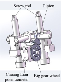
2.3. High-overload structure design of new electromagnetic shell electric actuator
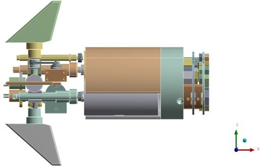
Because of the small volume of the electric rudder cabin of the electromagnetic shell, the rolling screw drive structure was selected in this study. As shown in Fig. 3, to meet the performance requirements of the steering gear, a new deceleration mechanism combining a triangular screw and a fork was developed to resist high overloads. According to the performance index requirements listed in Table 1, the rated output torque and speed of the motor were 30 N∙mm and 5000 rpm, respectively. When the rudder was unloaded, the maximum deflection speed of the rudder blade exceeded 190 °/s, which is equivalent to 31.67 rpm. The total deceleration ratio satisfies Eq. (1):
In Eq. (2), is the lead of the screw, and L is the distance from the rudder axis to the lead screw axis. The positions of rudder shaft and screw axis are shown in Fig. 3. The transmission ratio of the triangular screw is expressed as Eq. (3).
Fig. 2The control block diagram of high overload electromagnetic shell electric actuator
Fig. 3location of rudder shaft and lead screw axis
In this study, the pitch was set as 1. The length of the transmission lead screw and shift fork swing arm was set as 13.6. The reduction ratio of the transmission system was 85. Under the rated condition, the maximum torque and the maximum angular velocity of the rudder blade deflection were calculated using Eq. (3) and Eq. (4), respectively:
According to the calculation results of Eq. (3) and Eq. (4), the reduction ratio of motor and triangular screw met the design requirements. The electric actuator structure of the proposed anti-high load electromagnetic shell is presented in Fig. 4.
3. Analysis of dynamic characteristics of steering gear system of anti-high-overload electromagnetic shell
3.1. Modal analysis of steering gear system of electromagnetic projectile with high-overload resistance
Modal analysis is a type of fundamental linear dynamic analysis and is widely used to determine the vibration characteristics of mechanical structures. It can be used to avoid resonance in the early stages of mechanical structure design or induce vibrations at a specific frequency. Vibration characteristics are an important parameter to verify the reliability and stability of structural design under dynamic loads. The vibration model of the system is shown in Eq. (5):
where, – stiffness matrix of the system, – quality matrix of system, – external force matrix of the system, equals 0 in Eq. (5):
Fig. 4Structure of electric actuator of new anti high load electromagnetic shell
a) High overload transmission structure
b) Angle feedback structure
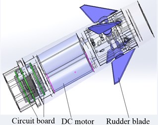
c) Electric actuator structure
Eq. (6) is taken into Eq. (5), then a second equation is shown in Eq. (7):
In Eq. (7), :
By solving the determinant equation , where is the natural frequency of the order , the main mode shape, , of the th natural frequency could be obtained. The simplified anti-high-overload electromagnetic shell actuator system model was imported into ANSYS and assigned materials. The main material of electromagnetic shell electric actuator was 40 Cr, and the material properties are shown in Table 2.
Table 2Material properties of steering gear system of anti-high overload electromagnetic shell
Material | Modulus of elasticity | Poisson’s ratio | Density | Yield strength | Tensile strength |
Steel | 2×10¹¹ Pa | 0.3 | 7850 kg/m3 | ≥ 785 MPa | ≥ 980 MPa |
The steering system model of the electromagnetic projectile against high overload was meshed. To balance the trade-off between computing time and meshing accuracy, the mesh size of this model was controlled at 3 mm. To maximize meshing quality, the hexahedron and tetrahedron integrated division method was adopted. Consequently, 265435 nodes and 148023 units were obtained, and the integrated meshing quality was 0.72, as shown in Fig. 5(a) and (b). The motor and the high-strength screws between the potentiometer and the cylinder wall were fixedly connected. The modal simulation of the steering gear was performed in a free state. The first six rigid body displacement modes were discarded. The first eight natural frequencies obtained from the modal analysis are shown in Table 3.
Fig. 5Meshing of steering gear system
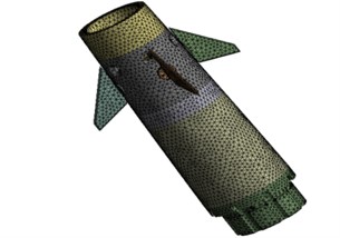
a) Meshing model
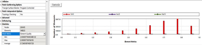
b) Meshing quality
Table 3The first eight natural frequencies of the steering system model of anti-high overload electromagnetic shell
Order | 1 | 2 | 3 | 4 | 5 | 6 | 7 | 8 |
Natural frequency (Hz) | 1928.6 | 2167.3 | 3956.4 | 4834.1 | 5236.9 | 6969.7 | 7726.1 | 8751.9 |
The first eight vibration modes are shown in Fig. 6. It should be noted that the maximum vibration position of the fourth and eighth order modal inside the electromagnetic shell. In the figure, to clearly display the internal vibration modes of the steering gear system of the anti-high-overload electromagnetic shell, the cylinder wall is hidden.
Observe the deformation of the first six modes to know the vibration form of each mode, as shown in Table 4.
Table 4Description of the first six modes of the steering gear system of anti-high overload electromagnetic shell
Order | Mode description |
First | The upper shell and rudder plate swing along the y-axis |
Second | The rudder is twisted around the x-axis |
Third | The upper shell and rudder plate and rudder plate are twisted around the x-axis |
Fourth | The tail clapboard swings along the x-axis |
Fifth | The upper shell and rudder plate bend and twist around the y-axis |
Sixth | The upper shell and rudder plate bend and twist around the z-axis |
Seventh | Two rudders bend and twist around Y axis |
Eighth | The inner metal rod swings along the Z axis |
According to the above finite element calculation, the accuracy of the model needs to be verified using a free mode test. In this paper, the B & K modal test system was used. The test setup is shown in Fig. 7, which mainly includes an acceleration sensor and force hammer. During the free mode test, the rudder of the electromagnetic shell was suspended using an elastic rope. This modal test adopted the multi-point excitation single point response method. The acceleration sensor was fixed at one measuring point, and the moving hammer was used to knock each measuring point. To obtain accurate test results, 18 test points were marked on the surface of the tested piece, and each measuring point was knocked five times, and the measurements were averaged to eliminate random error. Then, each datum was recorded.
Fig. 6The first eight modes of the steering system model of anti-high overload electromagnetic shell
a) Vibration mode of first order
b) Vibration mode of second order
c) Vibration mode of third order
d) Vibration mode of fourth order
e) Vibration mode of fifth order
f) Vibration mode of sixth order
g) Vibration mode of seventh order
h) Vibration mode of eighth order
Fig. 7Modal test of electromagnetic shell steering gear
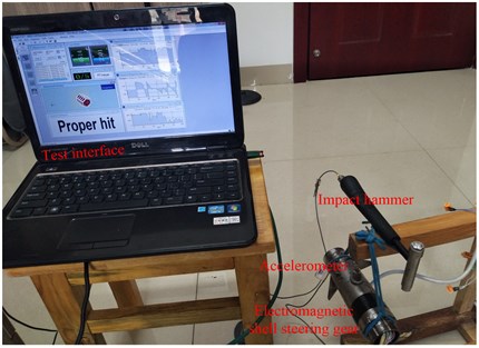
Table 5 shows a comparison between the test modal frequency and finite element calculation results. It was found that the maximum error between the first eight natural mode frequencies obtained experimentally and via the finite element calculation was 6.6 %, and that for the remaining modes was less than 5 %, which is acceptable in engineering applications. The above analysis validated the proposed electromagnetic shell.
Table 5The comparison of test modal frequency and finite element calculation frequency
Order | FEA value (Hz) | Measured value (Hz) | Error (%) | Order | FEA value (Hz) | Measured value (Hz) | Error (%) |
1 | 1928.6 | 1802.9 | 6.5% | 5 | 5236.9 | 4888.7 | 6.6% |
2 | 2167.3 | 2135.6 | 1.4% | 6 | 6969.7 | 6652.2 | 4.5% |
3 | 3956.4 | 3872.2 | 2.1% | 7 | 7726.1 | 7511.8 | 2.7% |
4 | 4834.1 | 4573.3 | 5.3% | 8 | 8751.9 | 8503.9 | 2.8% |
3.2. Transient dynamic analysis of actuator system of electromagnetic projectile with high-overload resistance
A transient dynamic analysis was performed to determine the dynamic response of a structure under arbitrary time-varying loads. Particularly, the displacement, strain, and stress of the system structure under a random combination of steady-state load, transient load, and simple harmonic load were determined. These are important indexes to evaluate the anti-high-overload performance of the system structure. The basic motion equation of the system is shown in Eq. (9):
where is mass matrix, is damping matrix, is stiffness matrix, is node acceleration vector, is node velocity vector, is node displacement vector.
At any instant, Eq. (5) can be regarded as a series of mechanical balance equations considering inertia force and damping force . The time increment integration time step is initialized, and the New-mark time integration method is used to solve this equation at discrete time points.
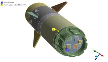
According to the requirements of technical indicators, the electric actuator of the electromagnetic shell should meet the high-overload requirements of an axial overload of 120000 N and a transverse overload of 40000 N. To facilitate the application of the impact load to the model, the three-dimensional coordinates of the model were first set, as shown in Fig. 8. Then, the horizontal direction parallel to the motor axis on the right was set as the positive longitudinal -axis direction, vertical to the motor axis to the up as the transverse -axis positive direction, and vertical to the motor axis. The positive vertical -axis direction was set in the direction of the motor shaft and was horizontally outward.
Fig. 8Three dimensional coordinates setting of anti high overload electromagnetic shell steering gear system
3.2.1. Longitudinal transient impact analysis
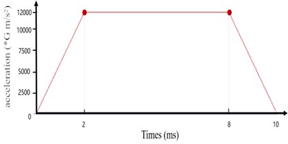
A longitudinal (positive axis) transient impact acceleration of 12000 g was applied to the actuator system model of the electromagnetic projectile, and the high-strength screws between the motor and potentiometer and the cylinder wall were fixedly connected. The eight bolt holes of the cylinder wall were fully constrained. Because the acceleration time of electromagnetic projectiles in electromagnetic orbit is generally short, the impact time was set as 10 ms. During this time, the projectile rises for 2 ms, stays in orbit for 6 ms, and falls for 2 ms. Fig. 9(a) and (b) show the longitudinal transient impact analysis boundary conditions and diagram of the longitudinal transient impact time load, respectively.
Fig. 9a) Longitudinal transient impact analysis boundary conditions; b) time load diagram of longitudinal transient impact
a)
b)
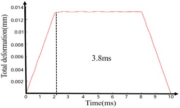
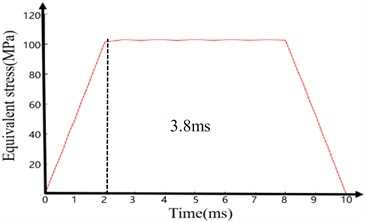
The analysis results are shown in Fig. 10 and Fig. 11. Fig. 10 shows the dynamic characteristic curve of the maximum deformation and maximum equivalent stress of the actuator system model of the electromagnetic shell under the longitudinal transient impact load. At 0-2 ms, the system responds rapidly, and its maximum deformation and maximum equivalent force increase rapidly (0.013 mm for total deformation and approximately 103 MPa for equivalent stress). Subsequently, these parameters remain stable until 8 ms, when the 12000 g transient impact load is removed. Thereafter, the values of these two parameters decline until the load is removed at 10 ms. The deformation and equivalent stress are reduced to 1.63e-4 mm and 1.12 MPa, respectively.
Between 2 ms and 8 ms, the maximum deformation and equivalent stress only fluctuate slightly and maintain their extreme values. Therefore, the deformation and the equivalent stress can be observed at any instant of this duration. Fig. 11(a) and (b) show the deformation and the equivalent stress, respectively, of the electromagnetic shell steering system model at 3.8 ms. From the figure, the maximum deformation of the coaxial rudder is 0.013 mm owing to its weak stiffness and the maximum equivalent stress (103.08 MPa) occurs on the cylinder wall. However, the maximum equivalent stress is significantly less than the 785 MPa yield strength of 40 Cr. The actuator system of the electromagnetic shell did not undergo plastic deformation under the longitudinal impact load. Thus, it meets the structural strength requirements of longitudinal high-overload resistance.
Fig. 10Model of electromagnetic shell steering gear system under longitudinal transient impact load
a) Time-deformation curve
b) Time-equivalent stress curve
Fig. 11Longitudinal transient impact electromagnetic shell steering system model at 3.8 ms
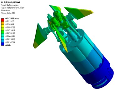
a) Deformation
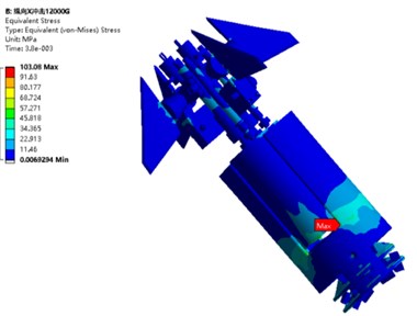
b) Equivalent stress
3.2.2. Lateral transient impact analysis
A transverse (positive -axis) transient impact acceleration of 4000 g was applied to the steering gear model of the electromagnetic shell, and the high-strength screws between the motor and potentiometer and the cylinder wall were fixedly connected. The eight bolt holes of the cylinder wall were fully constrained. The impact time was set as 10 ms, during which the projectile rises for 2 ms, stays in orbit for 6 ms, and falls for 2 ms. Fig. 12(a) and (b) show the lateral transient impact analysis boundary conditions and diagram of the transverse transient impact time load, respectively.
The analysis results are shown in Fig. 13 and Fig. 14. Fig. 13 shows the dynamic characteristic curve of the maximum deformation and equivalent stress of the steering gear system model of the electromagnetic shell under the transverse transient impact load. At 0-2 ms, the system responds rapidly, and its maximum deformation and equivalent stress increase rapidly (0.059 mm for total deformation and approximately 108 MPa for equivalent stress). When the 4000 g transient impact load is removed, the maximum deformation and equivalent stress fluctuate slightly until 8 ms. Subsequently, the deformation and equivalent stress decrease to 1.17e-3 mm and 2.218 MPa, respectively.
Fig. 12a) Lateral transient impact analysis boundary conditions; b) lateral transient impact time load diagram
a)
b)
Fig. 13Model of electromagnetic shell steering gear system under transverse transient impact load
a) Time-deformation curve
b) Time-equivalent stress curve
Fig. 14Transverse transient impact electromagnetic shell steering system model at 3.8 ms
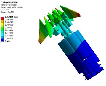
a) Deformation
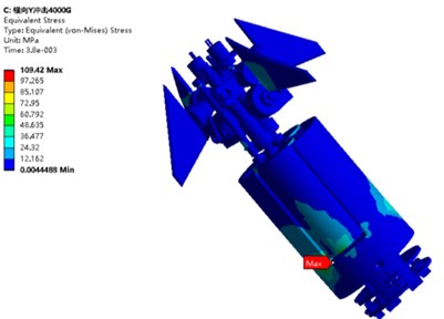
b) Equivalent stress
For the longitudinal transient impact analysis, the deformation and the equivalent stress of the electromagnetic shell steering gear system model under the transverse transient impact load at 3.8 ms were considered, as shown in Fig. 14(a) and (b). As shown in the figure, the maximum deformation occurs on the coaxial rudder blade, reaching 0.059 mm; this indicates an increase of 3.5 times compared with the deformation of 0.013 mm under the longitudinal transient impact. This is because the transverse stiffness of the steering system model of electromagnetic shell is less than the longitudinal stiffness. The maximum equivalent stress (109.42 MPa) also occurs on the cylinder wall, which is significantly less than the yield strength of 40 Cr at 785 MPa. The electromagnetic shell steering system did not undergo plastic deformation under the transverse impact load, thereby indicating that it meets the structural strength requirements of transverse high-overload resistance.
4. Establishment and analysis of the dynamic mathematical model of electric actuator system of anti-high-overload electromagnetic shell
4.1. Establishment of mathematical model of electric actuator system for anti-high-overload electromagnetic shell
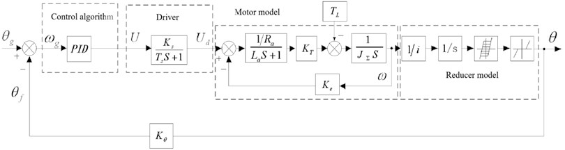
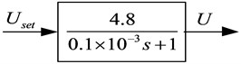
To achieve fast tracking command response and a high-precision index for the electric actuator system of the anti-high-overload electromagnetic shell, a dynamic mathematical model of the actuator system was established, and the transfer function of each part was calculated. The mathematical model block diagram of the electromagnetic shell electric actuator is shown in Fig. 15. The first, second, third, and fourth dotted boxes represent the PID control algorithm, drive model, motor model, and reducer model parts, respectively.
Fig. 15Mathematical model block diagram of electric actuator
4.2. Mathematical model simulation of the electric actuator of the electromagnetic shell with high-overload resistance
Using MATLAB/Simulink, the data were incorporated into the mathematical model of the electric actuator system.
Under the application of an external load moment , the open-loop and closed-loop transfer functions of the electric actuator are shown in Eq. (10) and Eq. (11) respectively:
The motor parameters are as follows: rated power 15 W, rated voltage 24 V, maximum current 2.7 A, rated speed 5000 RPM, rated torque 30 N⋅mm, motor internal resistance 7.53 Ω, locked rotor current 18 A, speed constant 208 RPM/V, mechanical time constant = 9 ms, total reduction ratio 85, and total delay of driver = 0.1 ms.
Since the rated voltage is 24 V and the rated speed of the actual motor is 5000 r/min, the motor back EMF constant is shown in Eq. (12):
When the rated electromagnetic torque of the motor is 30 N⋅mm, the motor current is 0.650 A. The torque constant of the motor is shown in Eq. (13):
The motor rotor inertia is 12×10-7 K and load inertia is 1.5×10⁻³ K. The equivalent motor inertia is shown in Eq. (14):
The mathematical model of the motor obtained with the above data is shown in Fig. 16.
Fig. 16Motor model
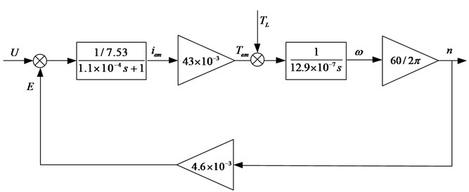
The transfer function of the motor model is shown in Eq. (15):
By omitting the higher-order terms and simplifying the equation, we obtain the following:
The total delay of the H-bridge was calculated according to the following formula, and the H-bridge model is shown in Fig. 17.
Fig. 17H bridge model
We used MATLAB/Simulink to build the overall mathematical simulation model of the electric actuator, which is shown in Fig. 18.
The given position is used as the input signal, and the position feedback is considered as the output. Its transfer function is shown in Eq. (17):
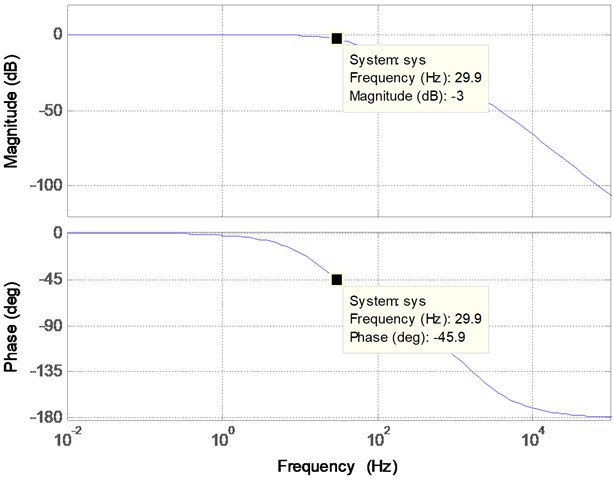
In practical engineering problems, Bode diagrams are frequently used to analyze the frequency characteristics of systems. The Bode diagram of the transfer function of the proposed system was obtained using MATLAB and is shown in Fig. 19.
According to the Bode diagram, when the system gain is –3 dB, the system frequency is 29.9 Hz, and phase delay is –45.9°. The simulation results show that the system response tracking is good; the bandwidth reaches 26 Hz; the rise time and overshoot of the system step response are within the index range; the dynamic characteristics are good; and the requirements of the project indicators are met well.
Fig. 18Simulation model of electric actuator
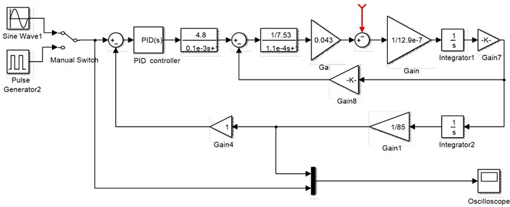
Fig. 19Bode diagram of steering gear system
5. Prototype manufacturing and experimental verification
To verify the performance of the new high-overload electromagnetic shell electric actuator, an electromagnetic shell electric actuator prototype was manufactured, and a set of electric actuator test systems was developed, as shown in Fig. 20. The test principle of the new high-overload electromagnetic shell steering gear mainly involved inputting different steering instructions to the steering gear through an industrial control machine. By comparing the command signal with the feedback signal, the index parameters of the steering gear were obtained.
5.1. Analysis of maximum mechanical rudder deflection angle
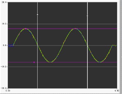
The maximum rudder deflection angle of the steering gear mainly depends on the effective electric stroke of the potentiometer and the mechanical stroke of the reducer. To verify the design requirements of the maximum rudder angle of the new high-overload electromagnetic shell actuator, the actuator controller sent sine wave commands with an amplitude of ±15° and a frequency of 0.50 Hz. The maximum rudder deflection test results are shown in Fig. 21. As evident from the figure, the feedback signal exhibits the variation characteristics of the input signal of the control system. The amplitude of the feedback signal has no attenuation, and the phase delay is 10°. The maximum rudder deflection angle meets the design requirements shown in Table 1.
Fig. 20Prototype and test system of new high overload electromagnetic shell steering gear
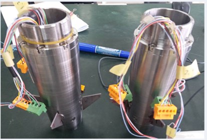
a) Electromagnetic shell electric steering gear prototype
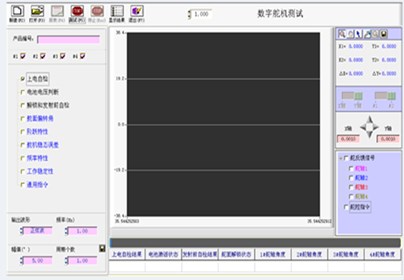
b) Test software interface
Fig. 21Test results of maximum rudder deflection angle
5.2. Frequency response characteristic analysis
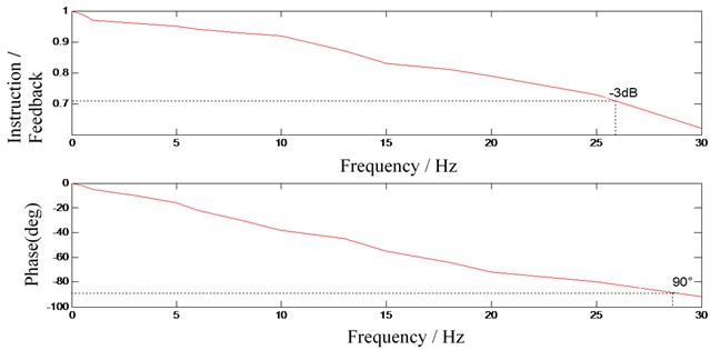
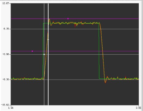
To verify the frequency response characteristics of the new high-overload electromagnetic shell actuator, the master computer sent various sinusoidal signals at frequencies of 1-30 Hz to the actuator controller. The signal amplitude and sampling frequency were ±2.5° and 1000 Hz, respectively. Fig. 22 shows the test results obtained using sinusoidal signals at 30 Hz. To improve the comprehensibility of the frequency response test results, the amplitude attenuation and phase-shift curves corresponding to each frequency are shown in Fig. 23.
According to the curves of the amplitude attenuation and phase shift corresponding to each frequency in Fig. 23, when the amplitude is 2.5° and the input signal frequency is 1-30 Hz, the response characteristics of the system are satisfactory. With an increase in the input signal frequency, both the attenuation of the output signal and the phase delay increase gradually. When the sinusoidal frequency reaches 26 Hz, the amplitude attenuation of the output signal is close to 30 %, and its phase lag is less than 90°. The test results satisfy the performance requirements listed in Table 1.
Fig. 22Test results with frequency of 30 Hz
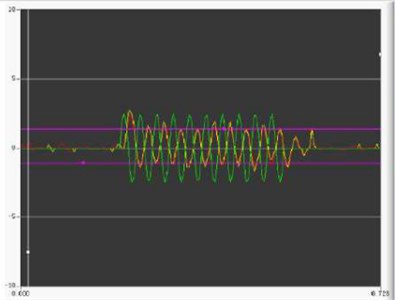
Fig. 23Amplitude attenuation and phase shift curve of each frequency
5.3. Analysis of step response characteristics
To verify the step response characteristics of the proposed high-overload electromagnetic shell actuator, the master computer sent an 8° square wave signal to the actuator controller. The sampling frequency of the system was 1000 Hz. The step response characteristics of the electromagnetic shell actuator are shown in Fig. 24. It can be observed that the time required for the rudder blade deflection to change from 0° to 8° is approximately 40 ms, which is within the required 60 ms, according to the design index in Table 1. The overshoot is 12.5 %, which is within the 20 % stipulated as per the design index. The maximum steering angle velocity of the steering gear is 198.46 °/s, which is lower than the design requirement of 200 °/s.
A comparison of the test results of the maximum rudder deflection angle and the frequency and step response characteristics of the experimental prototype with the simulation results of the system dynamic characteristics shows that the performance index of the test results is lower than that of the simulation results, but it still meets the requirements of the design index. Thus, the dynamic characteristic model of the actuator system of the proposed electromagnetic shell is validated. From the test results, we can observe that the servo system designed in this study performs satisfactory response tracking. The frequency response bandwidth of the system can reach 26 Hz, which meets the requirement of 25 Hz. The step response overshoot and rise time of the system are also within the requirements of the indicators.
The above analysis indicates that the proposed high-overload electromagnetic shell steering system has good dynamic characteristics and meets the design requirements.
Fig. 24Step response test results
6. Conclusions
1) Based on an analysis of the actuator system of an electromagnetic shell, the overall design strategy for the actuator system of a new type of anti-high-overload electromagnetic shell is proposed herein. Regarding the transmission structure characteristics of the actuator, a new anti-overload deceleration mechanism combining a triangle screw and a shift fork was designed, and the deceleration ratio of the new triangle screw was calculated to meet the requirements of the design index.
2) The dynamic model of the entire actuator was established based on modal theory. The natural frequency and vibration mode of the electromagnetic shell actuator were examined, and the dynamic characteristics of stress and strain of the model under transient impact loads were analyzed using the transient dynamic method. The results indicated that the new electromagnetic shell actuator structure met the requirements of high-overload resistance.
3) Based on the integrated module method of complex electro-mechanical equipment, a dynamic mathematical model of the steering gear system was established to analyze the dynamic characteristics of the steering gear system. The results indicated that the system response tracking was satisfactory; the bandwidth reached 26 Hz; and the rise time and overshoot of the system step response met the requirements for the dynamic characteristics of the system.
4) An experimental prototype of electromagnetic shell electric actuator was manufactured, and a set of electric actuator test systems was developed. By testing and analyzing the maximum mechanical rudder angle, we verified the frequency and step response characteristics of the experimental prototype, the correctness of the dynamic characteristic model of the proposed electromagnetic shell electric actuator system, and the performance of the new actuator system.
References
-
Wang Q., Geng Y. L. Electromagnetic gun and its characteristics and military application. National Defense Science and Technology, Vol. 32, Issue 2, 2011, p. 1-7.
-
Huang Y., Zhang C. F. The development of electromagnetic railgun and its niche approach. National Defense Science and Technology, Vol. 37, Issue 3, 2016, p. 33-35.
-
Cui X. Y., Li S., Feng H., et al. A triangular prism solid and shell interactive mapping element for electromagnetic sheet metal forming process. Journal of Computational Physics, Vol. 336, 2017, p. 192-211.
-
Li Z. Y., Xu Z., Gao Y. S., et al. Electric characteristic detection of a certain missile rudder. Journal of Academy of Armored Force Engineering, Vol. 2, 2008, p. 59-62.
-
Jin J. C. Research on the Anti-high-overload Technology for Military Integrated Circuit. Military Representative of the CPLA in No. 9373 Factory, 2008.
-
Hu B. Design and development of the digital servo control system for the rudder of the flying missile. University of Electronic Science and technology of China, 2012.
-
Yang X. M. S., Xu Y. Research on the coning motion of wrap-around fin projectiles. Canadian Aeronautics and Space Journal, Le Journal Aéronautique Et Spatial Du Canada, Vol. 52, Issue 3, 2006, p. 119-125.
-
Mu X. H., Niu Y. T., Ma X. B. Prospection on storage life of missile-borne control system under high overload. Equipment Environmental Engineering, Vol. 3, 2015, p. 115-120.
-
Lu J., Wu Z. G., Yang C. Modular modeling and dynamic stiffness simulation of electromechanical actuator. Journal of Beijing University of Aeronautics and Astronautics, 2020.
-
Yu J. K. A Thesis for the Degree of Engineering Design and Research of High Overload Inertial Sensors. Shenyang Ligong University, 2012.
-
Xu X. R. Study on High Overload Characteristics of Ultrasonic Electric Mechanical-Actuator. North University of China, 2018.
-
Chen Y., Xia Y. H., Liu W. Optimization design of the unlocking mechanism of the rudder surface of a high overload electric actuator. Scientific Consultation (Science and technology Management), Vol. 10, 2019.
-
Zhang B., Li C., Wang T., et al. Design and experimental study of zero-compensation steering gear load simulator with double torsion springs. Measurement, Vol. 148, 2019, p. 106930.
-
Fu W. X., Sun L., Yu Y. F., et al. Design and modeling of large torque electric load simulator. System Simulation, Vol. 21, Issue 12, 2009, p. 3596-3602.
-
Xia J. S. The Application and development of high overload environmental adaptivity technology for MCM. Environmental Adaptability and Reliability, Vol. 3, 2018, p. 21-24.
-
Zhao X. Z. Anti-high-overload Design and Application for Electronic Recording System. North University of China, 2008.
-
Liu X., Yang R. F., Jia J. F. Suppression of superfluous force of electric load simulator. Advanced Materials Research, Vol. 562-564, 2012, p. 1917, p. 1483-1486.
-
Xu X. R., Xiu T., Fu H. W., et al. Study on high overload characteristics of ultrasonic electric actuator. International Conference on Intelligent and Interactive Systems and Applications, 2017.
-
Ruzbehi S., Hahn I. Topology optimization with improved genetic algorithm of an electromagnetic actuator. 22nd International Conference on the Computation of Electromagnetic Fields, 2019.
-
Su C. P., Wang X. M., Xu Z., et al. Schroeder phased harmonic signal applied in frequency response test of missile steering gear system. IEEE CSAA Guidance, Navigation and Control Conference, 2020.
-
Luo D. C., Wang S. C., Liu Z. G. Application of household in the frequency domain modeling of the lateral-normal stabilizer of missile. Journal of Projectiles; Rockets; Missiles and Guidance, Vol. 25, Issue 2, 2005, p. 614-616.
-
Hao W. L., Li F. H., Xu H. L. Frequency domain modeling method excited by SPHS and MATLAB. China Measurement Technology, Vol. 31, Issue 6, 2005, p. 46-49.
-
Zhou J. B., Li L. Frequency response testing method based on SPHS signal. Industrial Control Computer, Vol. 29, Issue 11, 2016, p. 39-41.
-
Sun L., Xu Y. Modal parameter identification and finite element model updating of a long-span aqueduct structure based on ambient excitation. Journal of Vibroengineering, Vol. 22, Issue 3, 2020, p. 896-908.
About this article

The author(s) disclosed receipt of the following financial support for the research, authorship, and/or publication of this article: The Taiyuan Heavy Machinery Equipment Collaborative Innovation Center; and Project of Hunan Science and Technology (2016RS4056).
