Abstract
Based on the existing UHPC material parameters, masonry parameters and the application of reinforcement projects on the market, ABAQUS's unique concrete plastic damage (CDP) constitutive model can be used for concrete and other brittle materials. The constitutive parameters are obtained by curve fitting experiments by other scholars, and this paper has carried out appropriate calibrations. Numerical analysis is the pseudo-static loading form of UHPC reinforced low-strength masonry walls. Through the analysis and simulation of the hysteresis curve, skeleton curve, equivalent plastic strain Moire diagram, peak stress, strain and other parameters, the changes in shear resistance before and after UHPC reinforced masonry walls are evaluated.
Highlights
- Based on the concrete plastic damage (CDP) model of ABAQUS, the seismic performance of masonry walls before and after UHPC reinforcement is simulated and analyzed.
- UHPC material provided by a company is to be used, and the parameters of brick wall are determined by actual engineering test.
- In this paper, two masonry walls are designed. The unreinforced wall is named W-1 and the reinforced wall is named W-2.
- The cracking load of the wall is increased by 145%, which indicates that the UHPC reinforcement layer and the wall have achieved a good synergistic effect, and the reinforcement effect is good.
1. Introduction
According to statistics, there are a large number of old masonry buildings in many parts of the world, some of which have not reached the service life but have safety problems. The concept of ultra-high performance concrete (UHPC) was proposed by Larrard et al. [1] in 1994. Unlike traditional concrete, UHPC has excellent properties such as ultra-high strength, high toughness, low permeability and high volume stability. After decades of development, it has taken the lead in getting good applications in bridge engineering and reinforcement engineering: In 2004, the Swiss Chillon [2] viaduct was re-paved with UHPC decks and the structure was reinforced and repaired; From 2004 to 2008, Denarie E., Habel K., Bruhwiler E. jointly made a series of in-depth studies on the use of UHPFC materials to strengthen reinforced concrete beams, and explored the impact resistance of UHPFC reinforcement layer and the performance of the bridge deck waterproof layer [3]; In 2011, China applied UHPC to the reinforcement project of Zhaoqing Mafang Bridge, and the problem of serious damage and fatigue cracking of the steel box main girder pavement layer was solved well after testing [4]; In 2017, the U.S. Federal Highway Administration used UHPC materials to strengthen the I-beam of a highway bridge. After the test, it was found that the bearing capacity was 28 % higher than the intact I-beam and 473 % higher than the corroded I-beam[5]; Zhang Yang et al. [6] used UHPC to reinforce the old reinforced concrete (RC) structure, which has been verified by experiments to greatly improve its crack resistance, waterproofing and durability.
Among all the proposed methods to predict the structural response of masonry buildings under earthquake action, the finite element modeling (FEM) strategy is the most commonly used, which allows the expression of the type characteristics of buildings and the mechanical properties of materials with different detail scales [7]. Zhu Chengcheng et al. [8] used ABAQUS to establish a horizontal reinforcement masonry model, and studied the influence of reinforcement spacing on the reinforcement effect through elastoplastic dynamic analysis; Garofano et al. [9] used DIANA software to establish a finite element model of polymer mortar surface reinforcement masonry, and analyzed the masonry strength, wall shape, mortar strength and other factors; Susila et al. [10] considered the sliding effect of the mortar interface, and used ABAQUS modeling to study the performance of the bamboo pole perforated reinforced masonry, and the damage shape and bearing capacity fit well; Dolatshahi et al. [11] used the ABAQUS/Explicit module to study the main influencing factors of the wall's deformability, and the failure mode simulation was good; Zhang Si et al. [12] used the ABAQUS zero-thickness Cohesive element to establish a fiber cloth reinforced masonry separation model under consideration of the masonry form, and conducted a study on the performance under low-cycle reciprocating loading.
Based on the above discussion and the existing reinforcement experience, UHPC materials are applied to the reinforcement of masonry structures. This paper simulates the reinforcement of low-strength brick walls based on the UHPC parameters provided by a company, and designs the ABAQUS finite element simulation numerical analysis model to verify and analyze it, so as to provide actual engineering as a reference.
2. FEM of masonry wall
2.1. Basic parameters of the wall
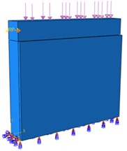
Based on the wall reinforcement situation encountered in actual projects, the prototype wall size is 3480 mm×2520 mm×240 mm, and 1/4 of the wall is taken for discussion, that is, the wall size to be simulated is 1740 mm×1260 mm×240 mm. Considering that the wall has been built for a long time, the masonry mortar is set as lime mortar with a strength of less than 1MPa to simulate the actual situation. Set up two walls, the unreinforced wall number is W-1, the UHPC single-sided reinforced wall number is W-2, and the thickness is 40 mm. This paper uses the pseudo-static method to simulate, placing the top beam on the top of the wall. According to the actual forces on the two walls, a compressive stress of 0.18 MPa is applied to the top of the top beam, and a horizontal reciprocating force is applied to the side of the top beam to simulate the effect of the earthquake. Fig.1 is the dimension drawing of the unreinforced wall, and Table 1 and 2 are the basic mechanical parameters of the wall and UHPC respectively.
Fig. 1Dimensions of unreinforced wall (mm)
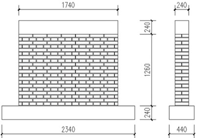
Table 1Masonry material strength
Material | Brick | Masonry mortar (measured) |
Strength / MPa | 6.20 | 0.6 |
Table 2UHPC material strength
Compressive strength / MPa | Tensile strength / MPa | Elastic modulus / GPa | Steel fiber volume content |
137.6 | 5.8 | 48.5 | 1.5 % |
2.2. Construction of FEM
Lubliner et al. [13] first proposed a damage plasticity constitutive model and used it for concrete with a small amount or even zero reinforcement. This constitutive model can simulate the influence of irreversible damage related to the failure mechanism of concrete and other quasi-brittle materials under low confining pressure [7].
The basic components of the masonry structure are blocks and mortar. Based on the details of the masonry elements expressed by the modeling, the calculation workload and the information about the structural behavior they provide, the modeling strategy can be divided into micro modeling and macro modeling [7]. In order to make the modeling simple and easy and reduce the amount of calculation, this article chooses the macro modeling form. That is to say, this article only considers the macroscopic force of the model, ignoring the cracking of the mortar joint between the block and the mortar, the bond slip between the block and the mortar and other interactions.
The elements involved in the model include solid elements, contact elements, etc., among which all material parts are modeled by solid elements C3D8R. The Tie command can make the two contact surfaces realize stress discontinuity and displacement continuity at the same time, which is more suitable for this model. Use the Tie command to bind the top beam and the masonry wall, and the UHPC reinforced surface layer to the masonry wall, ignoring the slip between the two.
There are two kinds of loads involved in this article: one is the vertical load applied in advance on the top of the loading beam, fixed at 0.18MPa; the other is the horizontal reciprocating force applied on the side of the loading beam. In order to improve the calculation convergence of the model, this paper converts the reciprocating force into displacement control, which is achieved by setting the Amp amplitude in the boundary conditions.
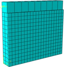
The finite element model before and after wall reinforcement is shown in Fig. 2 and 3.
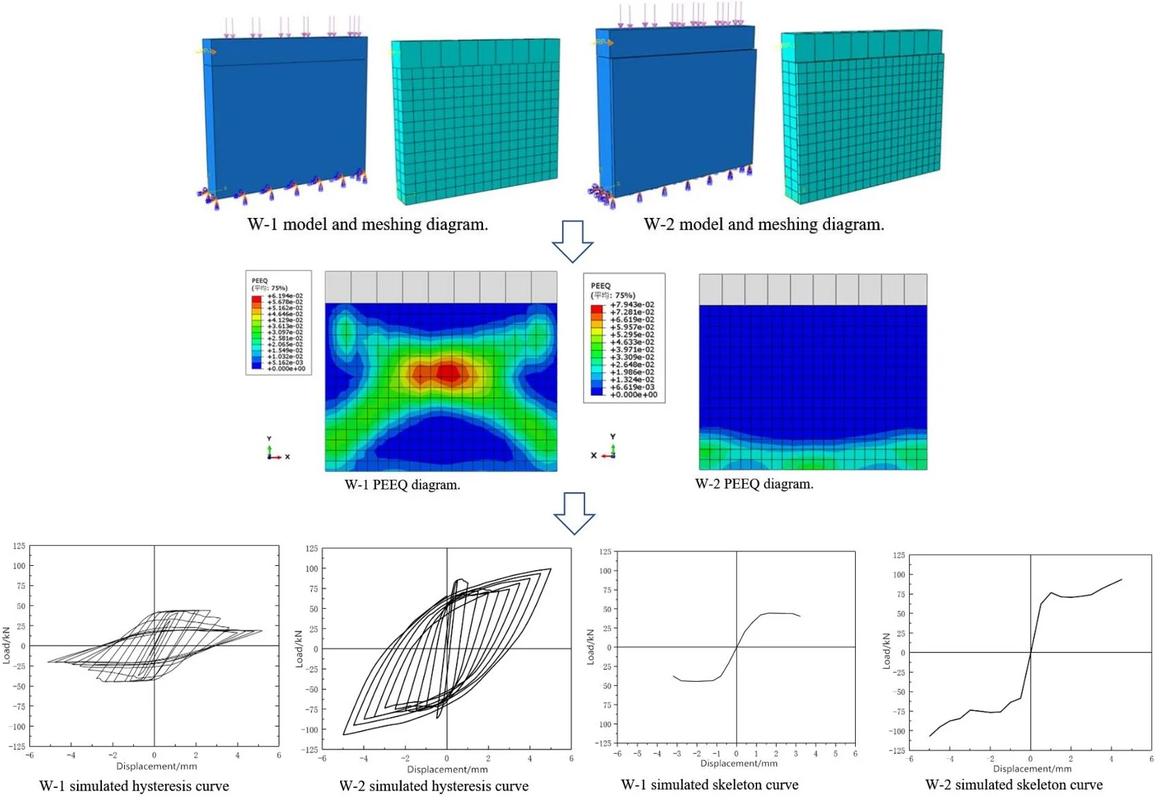
Fig. 2W-1 model and meshing diagram
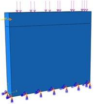
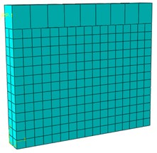
Fig. 3W-2 model and meshing diagram
2.3. Masonry constitutive model and failure criterion
Many scholars have explored the stress-strain relationship of masonry compression. Literature [14] compared the uniaxial compression constitutive model of masonry proposed in literature [15-19], and concluded that the constitutive model proposed by Yang Weizhong [17] can meet the mathematical characteristics of the compression stress-strain curve of the masonry structure. The formula is:
where is the ratio of the initial elastic modulus to the peak secant modulus; is the external compressive stress; is the strain at the peak of the stress-strain curve; is the average value of the axial compressive strength of the masonry.
For masonry tensile stress-strain relationship: in practice, mortar joint cracking is the main form of failure of masonry under tension, and masonry and concrete [20] have similar characteristics of brittle failure under tension. The specific relationship is:
where ; ; is the concrete uniaxial tensile stress-strain curve descending section parameter, according to the literature [21], ; is the representative value of concrete uniaxial tensile strength; is the peak tensile strain of concrete corresponding to ; is the evolution coefficient of concrete uniaxial tensile damage.
Unlike concrete, the tensile strength of masonry is relatively low. In the above formula, the value of will be too small, so that the descending section of the curve is too horizontal, and there is a big deviation compared with the actual situation. This paper refers to the solution in [22] and finds that the ascending section adopts a linear formula, and the descending section adopts a relational expression of . The revised formula is:
where ; ; is the tensile strain of the masonry; is the strain when the masonry tensile stress-strain curve reaches its peak; is the masonry tensile stress; is the average value of the axial tensile strength of the masonry.
When the CDP model enters the plastic damage stage, the concept of damage factor can be introduced to describe the material stiffness degradation phenomenon when the model is unloaded. Based on the energy equivalent principle proposed by Sidoroff [23], considering the stiffness reduction effect and combining with the uniaxial compressive stress-strain curve of masonry proposed by Yang Weizhong [17], the calculation formula of the compressive damage factor can be obtained as:
where ; ; ;
Regarding the determination of the tensile damage factor of the masonry, refer to the relevant calculations in [24]. The specific formula of damage factor is:
where ; ; .
2.4. UHPC constitutive model and failure criterion
Many scholars have done a lot of research on the UHPC uniaxial tension-compression constitutive relationship model, and the literature [25] summarized it. It is mainly divided into models based on elastic modulus, considering fiber type and content, considering curing methods, and based on water-binder ratio. And the agreement between the model and the experiment in the literature [26-29] is discussed.
For UHPC uniaxial compressive stress-strain curves, the constitutive models described in [26-29] each have their own scope of application. Among them, the literature [29] mainly studied concrete below 150 MPa, and the proposed concrete constitutive model can be better applied to the finite element study of ultra-high performance concrete below 150 MPa. The formula of the uniaxial compressive stress-strain constitutive model is as follows:
Note: According to the test results in the literature [29], it is determined that the parameter of the ascending section is ; and the parameter of the descending section is ; ; ; is the peak compressive strain of concrete.
For UHPC uniaxial tension constitutive model: Literature [30] and literature [31] have summarized and revised it, which has good applicability. UHPC tensile stress-strain curve equation is:
where is the tensile strain of UHPC; is the UHPC peak tensile strain; is the ultimate tensile strain of UHPC; is the value segment calculated according to the literature [30].
The CDP model simulation of concrete cracking can be expressed by “Tensile Strengthening”, through which the concrete cracking strain softening can be defined. For the determination of the plastic damage factor of UHPC materials, the literature [32] described in detail the damage variables and damage evolution of concrete in its article. According to the principle of energy equivalence, the formula for the one-dimensional concrete damage model is:
where is the tensile (compression) concrete damage factor; is tensile (compressive) stress; is tensile (compressive) strain.
2.5. Selection of material parameters
The calculation of masonry elastic modulus adopts the formula proposed by Shi Chuxian [15]:
According to the literature [33]: , , , .
According to the literature [34] and the ABAQUS operation manual on various parameters, the material parameter settings of the concrete damage plasticity model (CDP) include expansion angle , eccentricity , the ratio of biaxial compressive strength to uniaxial compressive strength , coefficient and the viscosity coefficient . The specific parameters are shown in Table 3, where is the mass density, kg/m3; is Poisson’s ratio; is the average value of axial compressive strength, MPa; is the design value of UHPC axial compressive strength, MPa; is the elastic modulus, MPa.
Table 3Material parameter values
Masonry | 1800 | 0.15 | 1.70 | \ | 820.08 | 30° | 0.1 | 1.16 | 0.6667 | 0.0005 |
UHPC | 2300 | 0.20 | \ | 137.6 | 48500 | 30° | 0.1 | 1.16 | 0.6667 | 0.005 |
3. Finite element analysis and calculation of masonry walls
3.1. W-1 analysis
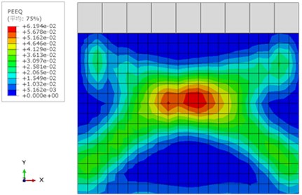
The equivalent plastic stress cloud diagram (PEEQ) module in ABAQUS describes the accumulation result of plastic strain during the entire deformation process. It is a monotonically increasing function. If it is greater than 0, it means that the material has reached the yield state, which can approximate the location and state of wall cracks. Fig. 4 below is the final PEEQ diagram obtained by numerical simulation of the W-1 wall.
Fig. 4W-1 PEEQ diagram
3.2. W-2 analysis
The strain state of the W-2 wall is represented by the equivalent plastic strain moiré diagram (PEEQ) module at the last moment of the calculation of the wall by the numerical simulation in ABAQUS, as shown in Fig. 5.
Fig. 5W-2 PEEQ diagram
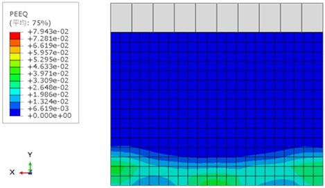
Under the action of horizontal reciprocating force, cracks appeared at the bottom of the wall first, concentrated in the corners of the two walls. Then with the increase of the horizontal force, the corner cracks gradually spread to the middle of the bottom of the wall, and finally penetrated the bottom of the wall, showing the characteristics of shear slip failure. Fig. 5 shows the unreinforced side of the wall. It can be seen that the crack positions of the reinforced wall (W-2) are mainly distributed at the bottom of the unreinforced surface of the wall, and the bonding between the reinforced surface and the wall is in good condition without cracking.
3.3. Comparative analysis of W-1 and W-2
Fig. 6 shows the hysteresis curve of W-1 wall drawn by numerical simulation. From the hysteresis curve, it can be seen that the wall can show a relatively full shuttle shape at the beginning of loading, and it is in the elastic stage at this time. As the loading progressed, the wall cracked and the hysteresis loop appeared to a certain degree of shrinkage, showing an increase in displacement and cracks. At this time, the wall entered the plastic working stage.
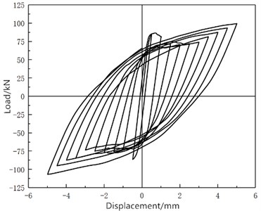
Fig. 7 shows the hysteresis curve of the W-2 wall after numerical simulation reinforcement. Under the horizontal reciprocating force of the W-2 wall, the hysteresis curve initially shows a linear development, at this time it is in the elastic stage. And compared with the hysteresis curve of W-1 wall in Fig. 6, the slope of the curve is larger, indicating that the rigidity of the wall reinforced by UHPC has been greatly improved. As the loading progresses, the wall cracks continue to develop, and at the same time, the shuttle-shaped hysteresis curve continues to develop outward, indicating that the UHPC reinforcement layer and the wall can maintain good integrity.
Fig. 6W-1 simulated hysteresis curve
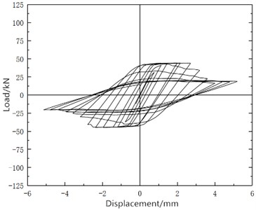
Fig. 7W-2 simulated hysteresis curve
The skeleton curves of W-1 and W-2 shown in Fig. 8 and 9 are obtained by connecting the peak points of each cycle on the hysteresis curve. By comparison, the skeleton curve of the UHPC reinforced wall in Fig. 9 is significantly higher than that of the unreinforced wall in Fig. 8. When the displacement is relatively large, the skeleton curve of the wall shown in Fig. 9 is smoother, and there is no obvious descending section. It can be shown that UHPC reinforcement can increase the shear capacity of the wall and slow down the rate of decrease of the bearing capacity.
Fig. 8W-1 simulated skeleton curve
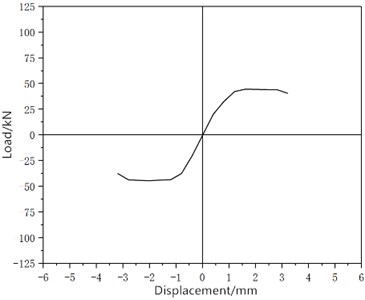
Fig. 9W-2 simulated skeleton curve
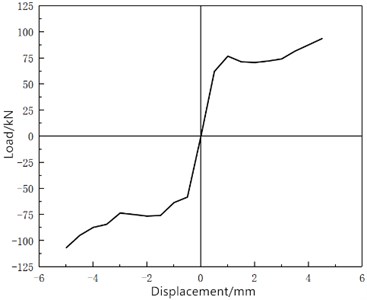
Table 4 shows the ultimate load before and after reinforcement and the displacement value under the ultimate load obtained by simulation analysis. By comparison, UHPC can effectively improve the shear bearing capacity of low-strength walls, and the cracking load of unreinforced walls has increased by 145 %.
Table 4W-1 and W-2 simulation data comparison
Project | Ultimate load / kN | Displacement under ultimate load / mm |
W-1 | 43.55 | 2.53 |
W-2 | 106.52 | 5.43 |
Difference (%) | 145 % |
4. Conclusions
1) This article discusses the application of UHPC in bridge reinforcement projects. Aiming at the increasingly severe safety problems of old masonry structures, the idea of UHPC strengthening old masonry structures is proposed. Through the use of ABAQUS nonlinear finite element tools for preliminary research and exploration.
2) In order to study the shear resistance of UHPC reinforced masonry walls, the concrete damage plastic model (CDP) in ABAQUS finite element analysis software was selected to simulate the walls before and after the reinforcement. After research, the concrete damage plastic model is effective in the analysis of the failure mechanism of masonry and UHPC components. Among them, the constitutive model parameters of masonry and UHPC materials can be determined by fitting curve data based on experiments; the damage factor data can be determined based on the energy equivalence principle proposed by Sidoroff and considering the stiffness reduction effect.
3) The use of macroscopic modeling can reduce the amount of calculation while ensuring the accuracy of calculation, so that the model can converge as soon as possible and save a lot of time.
4) Compared with the unreinforced wall, UHPC material can better improve the shear resistance of the wall. Under the action of horizontal force, the wall before the reinforcement will produce a larger stress at the corner of the wall, and finally form a shear-type failure along the diagonal direction. The simulated peak load value is 43.55 kN, and the displacement value under the peak load is 2.53 mm. After UHPC reinforcement of the wall, large stress mainly occurs at the corners of the wall, and eventually horizontal cracks penetrating through the bottom of the wall are generated, resulting in shear slip failure. The simulation calculation shows that the peak load value is 106.52 kN, and the displacement value under the peak load is 5.43 mm.
5) This paper only conducts the preliminary finite element study on the UHPC reinforced masonry structure, and lacks the comparative study of related experiments. The experimental study will be added later for comparison.
References
-
Larrard D. F., Sedran T. Optimization of ultra-high-performance concrete by the use a packing model. Cement and Concrete Research, Vol. 24, Issue 6, 1994, p. 997-1009.
-
Bruhwiler E. “Structural UHPFRC” to enhance bridges. Proceedings of the 2nd International Conference on UHPC Materials and Structures, 2018.
-
Tayeh B. A. Utilization of ultra-high performance fibre concrete (UHPFC) for rehabilitation. Procedia Engineering, Vol. 54, 2013, p. 525-538.
-
Shao Xudong, Qiu Minghong, Yan Banfu, et al. Research and application progress of ultra-high performance concrete in bridge engineering at home and abroad. Materials Review, Vol. 31, Issue 23, 2017, p. 33-43, (in Chinese).
-
Zmetra K. M. Experimental study of UHPC repair for corrosion damaged steel girder ends. Bridge Engineering, Vol. 22, Issue 8, 2017, p. 17-37.
-
Zhang Yang, Wang Xingwang Experimental study on the interface shear performance of UHPC reinforced RC structure. China and Foreign Highway, Vol. 37, Issue 2, 2017, p. 105-111, (in Chinese).
-
Resta M., Fiore A., Monaco P. Non-linear finite element analysis of masonry towers by adopting the damage plasticity constitutive model. Advances in Structural Engineering, Vol. 16, Issue 5, 2013, p. 791-803.
-
Zhu Chengcheng, Li Li, Li Haihong Dynamic analysis of horizontal inlay reinforcement based on ABAQUS masonry structure. Value Engineering, Vol. 37, Issue 12, 2018, p. 122-124, (in Chinese).
-
Garofano A., Ceroni F., Pecce M. Modelling of the in-plane behaviour of masonry walls strengthened with polymeric grids embedded in cementitious mortar layers. Composites Part B, Vol. 85, 2016, p. 243-258.
-
Susila G. A., Mandal P., Swailes T. Strengthening and retrofitting strategy for masonry (new build construction in Indonesia). Applied Mechanics amp; Materials, Vol. 848, 2016, p. 181-187.
-
Dolatshahi K. M., Nikoukalam M. T., Beyer K. Numerical study on factors that influence the in-plane drift capacity of unreinforced masonry walls. Earthquake Engineering and Structural Dynamics, Vol. 47, Issue 6, 2018, p. 1440-1459.
-
Zhang Si, Xu Lihua, Yang Dongmin, et al. Finite element model of mechanical behavior of brick masonry walls strengthened with fiber reinforced concrete. Engineering Mechanics, Vol. 32, Issue 12, 2015, p. 233-242, (in Chinese).
-
Lubliner J., Oliver J., Oller S., Oñate E. A plastic damage model for concrete. International Journal of Solids and Structures, Vol. 25, Issue 3, 1989, p. 299-326.
-
Li Fan Research on the Structure of Sandwich Wall and the Setting of Its Connecting Parts in Hot Summer and Cold Winter Area. Changsha University of Science and Technology, Changsha, 2017, (in Chinese).
-
Shi Chuxian Masonry Structure Theory and Design. China Building Industry Press, 2003, (in Chinese).
-
Liu Guiqiu Research on the Basic Mechanical Properties of Masonry Structures. Hunan University, 2005, (in Chinese).
-
Yang Weizhong Compression constitutive relationship model of masonry. Building Structure, Vol. 298, Issue 10, 2008, p. 80-82, (in Chinese).
-
Lu Weirong, Shi Chuxian Compression constitutive model of ordinary brick masonry. Building Structure, Vol. 36, Issue 11, 2006, p. 77-78, (in Chinese).
-
Zhuang Yizhou, Huang Chengkui Experimental study on the mechanical properties of model brick masonry. Building Structure, Vol. 2, 1997, p. 22-25+35, (in Chinese).
-
GB 50010-2010. Design Code for Concrete Structures. Building Industry Press, Beijing, 2010, (in Chinese).
-
Song Chenchen, Liu Jiming, Ai Tengteng, et al. Research on damage factors in ABAQUS concrete plastic damage model. Engineering Construction, Vol. 49, Issue 7, 2017, p. 1-5, (in Chinese).
-
Zheng Nina Research on Seismic Performance of Confined Masonry Structures with Prefabricated Structural Columns. Chongqing University, Chongqing, 2010, (in Chinese).
-
Sidoroff F. Description of Anisotropic Damage Application to Elasticity. Springer Berlin Heidelberg, 1981, p. 237-244.
-
Wang Beibei, Dong Jun Nonlinear finite element analysis of masonry walls based on damage plasticity model. Journal of Disaster Prevention and Mitigation Engineering, Vol. 34, Issue 2, 2014, p. 216-222, (in Chinese).
-
Guan Pinwu, Tu Yazheng, Zhang Pu, et al. Study on the constitutive relationship of ultra-high performance concrete under uniaxial tension and compression. Chinese Journal of Composites, Vol. 36, Issue 5, 2018, p. 1295-1305, (in Chinese).
-
Shan Bo Experimental and Research on the Basic Mechanical Properties of Reactive Powder Concrete. Hunan University, Changsha, 2002, (in Chinese).
-
Wu Youming Research on the Full Stress-Strain Curve of Reactive Powder Concrete (RPC) under Compression. Guangzhou University, Guangzhou, 2012, (in Chinese).
-
Shen Tao Study on the Constitutive Relationship and Structural Design Parameters of Reactive Powder Concrete under Uniaxial Compression. Harbin Institute of Technology, Harbin, 2014, (in Chinese).
-
Ma Yafeng Study on the Constitutive Relationship of Reactive Powder Concrete (RPC200) under Uniaxial Compression. Beijing Jiaotong University, Beijing, 2006, (in Chinese).
-
Chen Hongbo Research on Shear Behavior of Reinforced Ultra High Performance Concrete Short Beams. Hunan University, Changsha, 2014, (in Chinese).
-
Yuan Haiyan Experimental Study and Theoretical Analysis of Tensile Properties of Reinforced Reactive Powder Concrete. Ph.D. Thesis, Beijing Jiaotong University, Beijing, 2009, (in Chinese).
-
Liang Xingwen, Qian Lei, Tan Lina Research on the damage-plasticity constitutive relationship of concrete based on ABAQUS. Civil Construction and Environmental Engineering, Vol. 32, 2010, p. 646-648, (in Chinese).
-
GB 50003-2010, Code for Design of Masonry Structures. China Building Industry Press, Beijing, 2010, (in Chinese).
-
Lu Xinzheng Theoretical basis and latest development of seismic elastoplastic analysis of buildings. Working Committee of the Chinese Society of Mechanics to Promote the Integration of Engineering Application and Industry, Etc.: Chinese Society of Mechanics, 2012, p. 19-96+18, (in Chinese).
About this article

