Abstract
As road and bridge construction industry becomes more prosperous, the vehicle’s speed and load capacity increase significantly. This paper aims at the problem of vehicle-bridge coupling vibration of highway bridges. In this paper, based on the basic theory of vehicle-bridge coupled vibration, the differential equation of vehicle-bridge coupled system is obtained. The mode decomposition method is adopted to transform the system differential equation into a matrix form. The second-order development function based on the built-in function was written by the principle of Runge-Kutta method, and the second-order time-varying differential equation group was solved. Taking the simply supported beam as an example, this paper studies the dynamic characteristics of bridge and vehicle under different speed and mass.
Highlights
- Considering the geometric nonlinearity of the bridge, the mid span displacement of the bridge does not increase linearly with the increase of velocity. The mid span displacement of bridge increases with the increase of vehicle mass.
- Considering the geometric nonlinearity of the bridge, the displacement of the vehicle body first increases and then decreases with the increase of the speed. The displacement of vehicle body increases with the increase of car body mass.
- With the increase of speed, the vertical acceleration of the vehicle body increases gradually. The vertical acceleration of the vehicle body is an important index affecting the stability of the vehicle. Low speed driving is one of the methods to reduce the vertical acceleration of vehicle body.
1. Introduction
With the increasing prosperity of bridge construction in recent years, the remarkable improvement of driving speed and load capacity, the bridge structure's weight is gradually reduced, the stiffness is more flexible, and the span is larger. The influence of the geometric nonlinearity of bridge structure on vehicle-bridge coupling vibration is rarely considered in many vehicle-bridge coupling vibration studies.
Zeng [1] established the vehicle bridge coupling system’s equilibrium equation using the vehicle model with 21 degrees of freedom. Chen [2] established a new vehicle bridge coupling model, and the resonance curve of the bridge under vehicle bridge coupling vibration was obtained. Shen [3] used the ODE function based on Runge Kutta’s method to compile the redevelopment function, which can easily solve the differential equation of vehicle bridge coupling system and obtain the numerical solution with high accuracy. Xiao [4] established the vehicle bridge coupling model under the quarter vehicle model and realized the bridges' vehicle bridge coupling calculation. Nguyen [5] proposed a frequency domain calculation method to solve the vibration equations of the heavy vehicle, which indicating that resonant frequency of the bridge system is not affected by the vehicle speed, while it is clearly influenced by the weight of the vehicle and the stiffness of the bridge system. Li [6] deduced the vibration equilibrium equation of the variable cross-section continuous beam bridge considering the geometric nonlinearity of the bridge, and calculated the vibration response with the Runge Kutta method.
Based on the principle of Runge Kutta’s method, the quadratic development function is compiled in this paper. The influence of geometric nonlinearity of the bridge can be more realistic to analyze the dynamic response of the structure. It is of great theoretical and practical significance in the design and construction of the bridge structure.
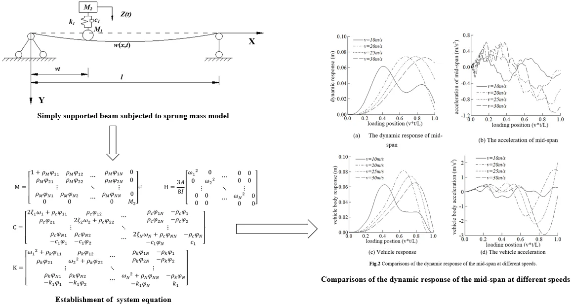
2. Establishment of system equation considering the geometric nonlinearity of the bridge
It is very important to consider the bridge’s geometric nonlinearity in analyzing vehicle-bridge coupling vibration, especially for bridges with small stiffness and large spans. Considering the bridge's geometric nonlinearity, the bridge's dynamic response can be analyzed more truly, which has important theoretical and practical significance for the structural design and construction.
Fig. 1Simply supported beam subjected to a sprung mass model
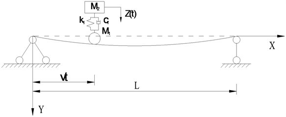
The systems can be simplified as Fig. 1. Where the , represents for the mass of body and tire respectively, the , represent for the Stiffness and damping respectively, and the means the time history of external load. The speed and time are used to represent the position of the body on the bridge at a certain time.
The system’s differential equation’s main derivation process considering the bridge's geometric nonlinearity is introduced below.
Firstly, the dynamic equilibrium equation of the supported beam can be described as:
According to the equilibrant above , the dynamic equilibrium equation can be directly derived:
The external load acting on the beam can be expressed as Eq. (3):
Based on the basic theory of coupled vibration of vehicle and bridge, the mode decomposition method is used to transform into the following equations:
The left end of the Eq. (4) can be transformed into:
where the , , represents for generalized displacement vector, generalized speed vector and generalized acceleration vector respectively. means the damping ratio.
Eq. (6) can be obtained by sorting out the above equations:
Similarly, the same methods are used in Eq. (2), and it can be written as:
By combining Eq. (6) with Eq. (7), the vehicle-bridge coupled vibration system’s dynamic balance equations can be obtained.
For supported beam systems, the -th matrix equation can be expressed as:
where the represents the generalized displacement vector, represents the generalized force vector, represents the generalized mass matrix, represents the generalized damping matrix, and represents the generalized stiffness matrix. The following matrices can describe this:
is used to describe the non-linear matrix, which can be written as:
where , , and .
From the elements in the non-linear matrix, it can be seen that the non-linear matrix is only related to the properties of the bridge, not to the parameters of the vehicle. It is also known that the value of the non-linear matrix will increase as the inertia moment decreases, while the other conditions remain unchanged.
3. Dynamic influence of common factors on the bridge
When cars pass over the bridge, vehicles passing at different speeds will cause changes in the bridge’s dynamic impact; also, the resonance will be caused when the vehicle’s external load frequency to the bridge is close to the natural frequency of the bridge.
Four speeds of 10 m/s, 20 m/s, 25 m/s, and 30 m/s are adopted in this section to study the dynamic response of the bridge and the vehicle. The effect of driving speed on the bridge is shown in Fig. 2. It can be seen from Fig. 2 that the maximum displacement response in the mid-span tends to increase with the increase of velocity. The driving speed increases from 10 m/s to 20 m/s and the corresponding increase of the maximum displacement in the span is significant. When the velocity is equal to 20 m/s, 25 m/s, and 30 m/s, there is no significant difference in the maximum displacement of the mid-span., which shows that the maximum displacement of span does not increase linearly with the increase of velocity. The maximum acceleration in the mid-span is increased with the increase in speed.
As can be seen from Fig. 2, the vertical acceleration of vehicle M2, which is a critical index affecting the vehicle stationary running, increases gradually as the speed increases.
Fig. 2Comparisons of the dynamic response of the mid-span at different speeds
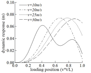
a) The dynamic response of mid-span
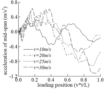
b) The acceleration of mid-span
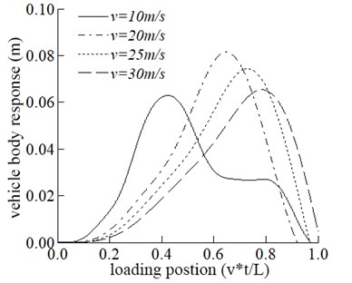
c) Vehicle response
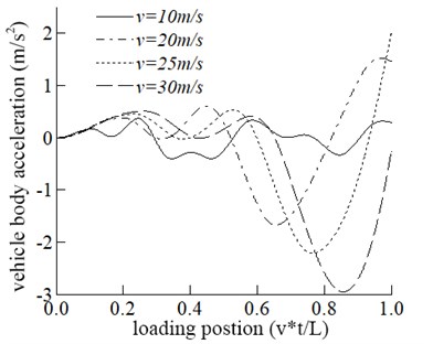
d) The vehicle acceleration
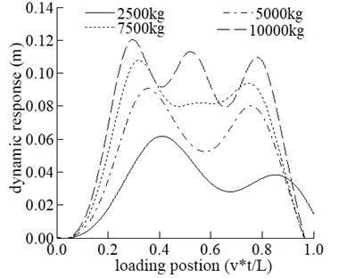
In this part, the vehicle mass is adopted as 2500 kg, 5000 kg, 7500 kg, and 10000 kg, respectively, to study the bridge’s dynamic response and the vehicle. The influence of different vehicle mass on the dynamic response of the bridge is shown in Fig. 3.
The maximum displacement in the span increases with the increase of vehicle mass. The influence of vehicle mass on mid-span displacement is generally apparent. It can be seen from Fig. 3 that the maximum acceleration in the middle span increases with the increase of vehicle mass.
Fig. 3Comparisons of the dynamic response of the mid-span at different mass
a) The dynamic response of mid-span
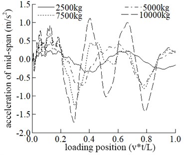
b) The acceleration of mid-span
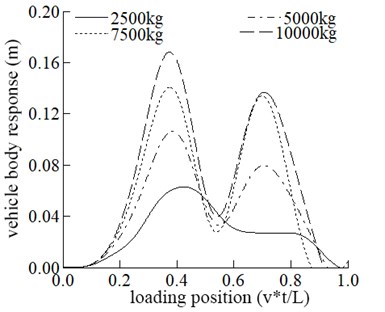
c) Vehicle response
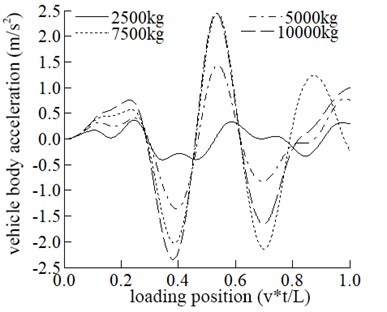
d) The vehicle acceleration
Fig. 3 that the maximum displacement and vertical acceleration of vehicle increase with the increase of its mass, and the positions where the maximum displacement and the maximum acceleration occur are the same.
4. Conclusions
In this paper, the influence of bridge geometric nonlinearity on a vehicle bridge coupling system's dynamic response is considered, and the equilibrium differential matrix equation is established. Matlab carries out numerical analysis of the system. The following conclusions are obtained.
1) Considering the geometric nonlinearity of the bridge, the mid span displacement of the bridge does not increase linearly with the increase of velocity. The mid span displacement of bridge increases with the increase of vehicle mass.
2) Considering the geometric nonlinearity of the bridge, the displacement of the vehicle body first increases and then decreases with the increase of the speed. The displacement of vehicle body increases with the increase of car body mass.
3) With the increase of speed, the vertical acceleration of the vehicle body increases gradually. The vertical acceleration of the vehicle body is an important index affecting the stability of the vehicle. Low speed driving is one of the methods to reduce the vertical acceleration of vehicle body.
References
-
Zeng Qingyuan, Yang Yi, Luo Ningan Lateral vibration analysis of train bridge time-varying system. Journal of the China Railway Society, Vol. 2, 1991, p. 38-46.
-
Chen Shen, Tang Yi, Huang Wenji Visual study on vehicle vibration simulation of rigid frame arch bridge under multi-vehicle load. Engineering Mechanics, Vol. 22, Issue 1, 2005, p. 218-222.
-
Shen Humming, Xiao Xinbiao A numerical method for solving the vibration problem of vehicle-bridge coupling. Journal of Southwest Jiaotong University, Vol. 38, Issue 6, 2003, p. 658-662.
-
Lin Hai, Xiao Zhengxie Dynamic analysis of beam bridge under automobile load. Journal of Chongqing Jiaotong University (Natural Science), 2000.
-
Nguyen V., Le V., Jiao R. Low-frequency vibration analysis of heavy vehicle suspension system under various operating conditions. Mathematical Models in Engineering, Vol. 6, Issue 1, 2020, p. 13-22.
-
Li Xuefeng, Yuan Jiadong, Mao Shangquan Vehicle bridge coupling vibration analysis of variable cross section bridge considering geometric nonlinearity. Chinese Journal of Applied Mechanics, Vol. 37, Issue 6, 2020, p. 2426-2433+2696-2697.
Cited by
About this article

