Abstract
The peak pressure and duration of high-pressure gas in the process of rock breaking by carbon dioxide fracturing will have a great impact on the fracturing effect of rock mass. For the sake of obtaining dynamic pressure response characteristic in the fracturing tube, the pressure-time curve of liquid CO2 blasting system was measured through several cavity pressure test of carbon dioxide fracturing tube. The cavity pressure test under different parameters of carbon dioxide quantity, activator quantity and thickness of energy release plate is carried out, in which TST6200 transient signal acquisition instrument, 109c12 type blasting shock wave sensor and special signal processing software system are used. The relation curve between pressure and time in the liquid CO2 fracturing tube was effectively measured and the variation law of pressure curve was analyzed. The results show that after igniting the liquid carbon dioxide fracturing tube, the cavity pressure rise slowly, then increases sharply and decays rapidly, when the pressure reaches the yield pressure limit of energy release plate, the energy release plate will be destroyed and high pressure gas will be released rapidly; the peak pressure in the CO2 fracturing system ranges from 169.1 MPa to 260.2 MPa, the duration of positive pressure is from 21.1 ms to 74.8 ms, and the peak pressure arrival time is between 13.2 ms and 67.7 ms. This paper attempts to establish the formula relationship between peak cavity pressure and thickness of energy release plate for carbon dioxide fracturing tube; the welded flat head formula, tensile failure formula and shear failure formula are used to calculate peak cavity pressure of carbon dioxide fracturing tube, in which the calculated results are compared with the measured values, the welded flat head formula severely underestimates the peak cavity pressure; conversely, the tensile failure formula slightly overestimated the peak cavity pressure; the shear failure formula can accurately reflect the peak cavity pressure of fracturing tube. The conclusions can be directly used for the design and optimization of fracturing tube by using different thickness energy release plate to control the cavity pressure of carbon dioxide fracturing tube.
Highlights
- The pressure-time curve of liquid CO2 blasting system was measured through cavity pressure tests of carbon dioxide fracturing tube.
- The relation curve between pressure and time in the liquid CO2 fracturing tube was effectively measured and the variation law of pressure curve was analyzed.
- The formula relationship between peak cavity pressure and thickness of energy release plate for carbon dioxide fracturing tube is established.
1. Introduction
As a kind of traditional technical means used in rock mass excavation, mining and tunneling, explosive blasting still plays an irreplaceable role in engineering construction due to its high efficiency, economy and simple operation [1, 2]. However, explosive blasting also brings many problems, such as: noise, slungshot, poisonous gas and harmful dust, sometimes even cause earthquake; the living environment, life health and personnel safety of people is seriously affected by the huge negative influence [3, 4]. In recent years, a new and efficient fracturing and tunneling technology, namely carbon dioxide (CO2) fracturing technology, has been gradually promoted in the field of rock excavation and coal mining. CO2 fracturing mechanism is a physical change, heating activating agent material encapsulated in the liquid storage tube, low temperature and high pressure CO2 gas environment generated by the CO2 blasting can create inert atmosphere, eliminating the possibility of methane explosion and secondary chemical reaction with other gases; there is no open flame or spark in the process of using the carbon dioxide fracturing technology, which improve safety in all aspects [5-8]. Thereby, carbon dioxide fracturing technology is widely used in open pit mine, coal mine, foundation pit engineering and can replace explosive as an excitation source for seismic exploration.
Since carbon dioxide phase change fracturing technology was introduced into China by Cardox International Corporation in 1990, it has been widely used in many engineering applications, such as coal seam permeability enhancement, hard roof weakening, quarry stone excavation, tunnel excavation, highway boulder blasting, urban subway foundation pit excavation, etc. Many universities and research institutes have broadly carried out research on the performance characteristics, fracturing test and engineering application of carbon dioxide fracturing device. Huang [9, 10] systematically introduced the basic structure, working principle and field application of carbon dioxide fracturing device, the rapid filling system and reasonable filling system structure design of carbon dioxide fracturing device is developed; Pressure of liquid carbon dioxide in the filling pipeline, filling weight and ambient temperature of the filling pump are automatically controlled through PLC program controller, thus the filling efficiency of carbon dioxide fracturing device is improved with preferably safe and reliable operation. Wu [11, 12] and Chen [13] conducted tests on the reliability and combustible gas safety of carbon dioxide fracturing device produced by different manufacturers in accordance with the “Safety Technical Requirements for Carbon Dioxide fracturing device” [14]; It was found that the initiation of carbon dioxide fracturing device was sometimes unreliable; the possible reasons are heterogeneous mixing of heating activating agent materials, insufficient purity of liquid carbon dioxide and unreasonable size of energy releasing sheet; which provides a safe basis for the promotion and use of new fracturing equipment in coal mine. Hong [15] simulated and optimized the geometric type and parameters of CO2 fracturing pipe by using Ansys Fluent, the effect of phase change fracturing points on fracturing is studied through the combined methods of theoretical analysis, numerical simulation and field test, CO2 phase change fracturing uses high-pressure gas to impact coal and rock, which enhances the fracture development and permeability of coal and rock; the influence radius of gas drainage presents a cubic function relationship with the amount of fracturing pipes. Coal mine researchers have been studying the subject of improving the effect of gas drainage to control gas accident. By applying the liquid carbon dioxide phase change fracturing technology, according to the results of field tests and numerical simulation, Chen [16] points out the radius of the damaged area in the coal body around the drilling reached 5 m. Also, compared with the original coal body, the permeability of the damaged area increased approximately six times. Directed at creating fractures and extracting methane in low permeability, high gas-outburst coal seams, Lu [17] presents the results of a comprehensive integration trial of under panel cross strata drilling with a new coal seam stimulation technique: the Cardox system in a colliery located in a major high gas content and outburst prone coal field in the central part of China. The Cardox system has the advantages of in creating fractures and improving gas drainage efficiency of low permeability coal seams. The study of the shock pressure is the premise to analyze the rock disintegration mechanism of liquid CO2 phase change fracturing. In order to obtain the phase-changing shock pressure, the relative dynamic signals are detected [18]. These signals include both dynamic strain and stress: the strain is about the dynamic response of the liquid CO2 storage tube, while the stress refers to the phase-changing shock pressure. The failure mechanism of storage tube was obtained as follows: the failure of the storage tube undergoes three states: elastic deformation, plastic deformation, and full plastic limit state. Huang [19] analyzed the shape and size parameters of release nozzle by using numerical simulation software Autodyn and proposed that suitable release nozzle structure for slope pre-splitting blasting is a cone, the nozzle shape should be a long rectangle with length of 18 mm, inlet width of 40 mm, exit width of 20 mm and shrinkage angle of about 30°. In order to increase coal seam permeability and improve gas drainage efficiency, Zhou [20] used the finite difference software FLAC3D to calculate the effective influence radius of liquid CO2 single hole blasting under different in-situ stresses, at the same time, the drilling parameters of liquid CO2 blasting technology were studied by carried out the simulation of multi hole continuous blasting and underground industrial CO2 blasting test. Dong [21] studied the TNT equivalent of liquid CO2 phase change fracturing by selecting the explosion model of compressed gas and steam container to calculate the TNT equivalent; the explosion of TNT in concrete block was simulated by Ansys-Ls-Dyna3D, the concrete crack and stress distribution are in good agreement with experimental results of liquid CO2 phase change fracturing. In view of the current situation of low permeability coal seam in China, for the sake of revealing the fracture variation pattern and the influence of different temperature and pressure conditions on the distribution of macroscopic crack number and length in process of supercritical CO2 gas explosion, experimental study of crack distribution laws caused by gas burst of supercritical carbon dioxide was carried out by using self-developed supercritical CO2 gas explosion experimental system; Sun [22] conducted supercritical CO2 gas explosion experiments on coal with different strengths under different temperature and pressure conditions, the number and length of cracks after explosion is analyzed. In order to further understand the crack propagation law and spatial morphology of supercritical CO2 fracturing, Liu [23] used acoustic emission monitoring, CT scanning and other technologies to conduct experimental research on shale fracturing with supercritical CO2 fracturing experimental device; Su [24] used fracturing test device to conduct physical experiment and preliminarily discussed the difference in fracture propagation morphology between hydraulic fracturing and supercritical CO2 fracturing in shale reservoir. In the process of fully mechanized coal mining face, the suspended roof in the triangular area of transport roadway and return air roadway is caused by the coal pillar support, which threatens the safety production of working face; Zhu [25] and Wei [26] successfully solved the suspended roof problem in the triangle area by carbon dioxide fracturing blasting; through the comparison of safety and economic benefits of carbon dioxide fracturing blasting and dynamite blasting, it is found that carbon dioxide fracturing blasting is economic and reasonable and will not damage the roadway and the support of working face. Wei [27] carried out CO2 pre-splitting blasting forced roof caving test on the hard roof in the mining process of fully mechanized working face of Xinjing Mine, which basically met the technical requirements of forced roof caving in production.
At present, in the study of carbon dioxide blasting effect, the research on the blasting mechanism of liquid CO2 phase change fracturing technology lags behind the engineering application, the changing process of temperature and pressure for liquid CO2 after heating expansion is unknown. It leads no quantitative data on the phase change fracturing ability of liquid CO2 and the blasting design has no theory to follow. There are few studies on the mechanism of carbon dioxide fracturing, quantification of blasting vibration effect and its effect on dynamic damage of rock mass, which need to be further studied through theoretical analysis, field test and numerical simulation. With the advancement of theoretical and practical research for high pressure gas fracturing technology, CO2 fracturing technology will have broad application prospects in the engineering construction.
The theoretical research of carbon dioxide fracturing blasting technology lags behind the engineering application. When installing the carbon dioxide fracturing device, the operators rely on experience in the selection of liquid carbon dioxide mass, activator mass and thickness of energy release plate because of lacking of accurate theoretical support and experimental verification. In the process of carbon dioxide blasting, the peak pressure of high-pressure gas can reach hundreds MPa [28, 29], the peak pressure and duration of high-pressure gas will have a great impact on the rock mass fracturing effect.
For improving the power of the liquid CO2 phase change fracturing technology, the pressure response characteristics of liquid CO2 blasting system were studied, the pressure of carbon dioxide fracturing tube was measured under different parameters of carbon dioxide mass, activator mass and thickness of energy release plate. In order to improve the effect of carbon dioxide fracturing, a mechanical model is established to provide real data support. As an important component of carbon dioxide fracturing device, energy release plate has great influence on the high pressure gas in the process of carbon dioxide fracturing, this paper attempts to establish the formula relationship between the peak gas pressure and the thickness of energy release plate of carbon dioxide fracturing device. The welded flat head formula, tensile failure formula and shear failure formula are used to calculate the peak gas pressure of the carbon dioxide fracturing device, respectively; the calculated results are compared with the experimental measured values. The conclusions can be directly used for the design and optimization on the energy release plate of fracturing tube, further improve the efficiency product performance of carbon dioxide fracturing device.
2. Theory
2.1. Carbon dioxide characteristic
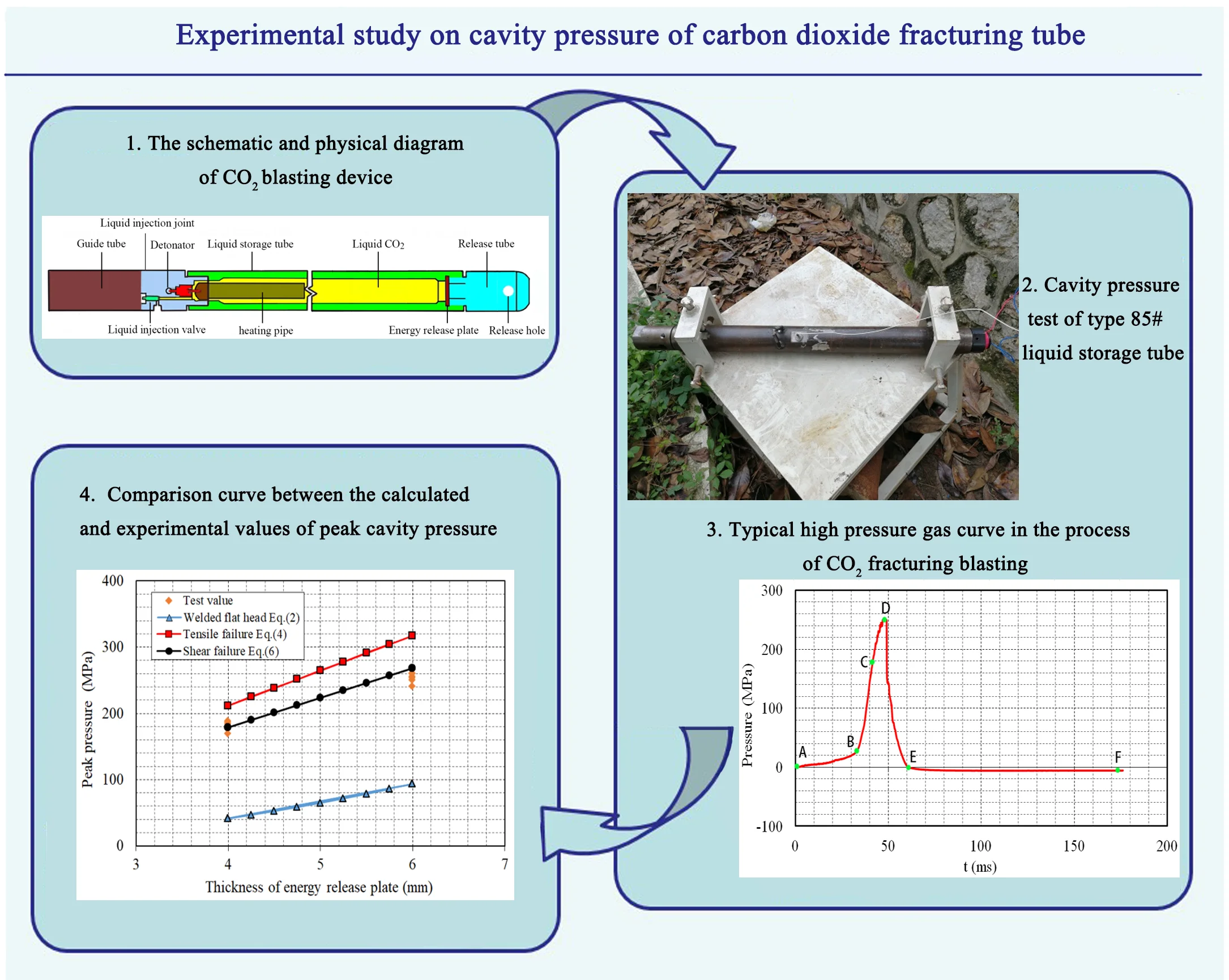
CO2 is a colorless, odorless, non-flammable and non-toxic gas at room temperature, the transition between gaseous, liquid and solid state is called phase change, which is controlled by the change of pressure and temperature and belongs to physical change [30]. There is a special supercritical state apart from the general gaseous, liquid and solid state; the relationship of CO2 phase, pressure and temperature is shown in Fig. 1, the CO2 turn into the supercritical fluid state when pressure is greater than 7.38 MPa and temperature is higher than 31.3 °C, which has a high molecular diffusion coefficient close to gas but has a high density close to liquid. It can continuously change from the normal state at normal temperature and normal pressure to the supercritical phase state. The conversion process among gas state, liquid state and supercritical state of carbon dioxide is shown in Fig. 2.
Fig. 1Three phase diagram of CO2
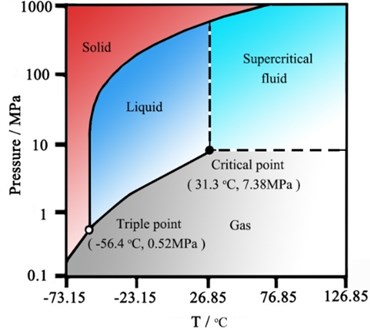
Fig. 2The conversion process among gas, liquid and supercritical state of carbon dioxide
2.2. Carbon dioxide fracturing device
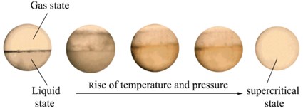
The CO2 fracturing device is composed of guide tube, liquid injection joint, liquid storage tube and release tube, where liquid injection joint and liquid storage tube are connected through a screw thread, which contains liquid injection valve, detonator, heating pipe and liquid CO2; in addition, release tube contains an energy release plate and release holes [3]. The schematic and physical diagram of CO2 blasting device is shown in Fig. 3.
Fig. 3The schematic and physical diagram of CO2 blasting device
a) The schematic diagram of CO2 blasting device
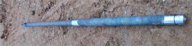
b) The physical diagram of CO2 blasting device
Guide tube is a kind of lifting tube which can conduct electricity and the internal wire is connected in both ends, the liquid injection joint is connected with guide tube through the thread. The main function of guide tube is to increase the length of fracturing tube when put the liquid storage tube and the release tube at the predetermined position, it is convenient to recycle the fracturing tube by lifting the guide pipe after fracturing blasting.
Fig. 4Liquid injection joint of CO2 blasting device
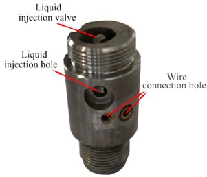
Liquid injection joint of CO2 blasting device is shown in Fig. 4. The liquid injection joint includes a liquid injection hole, a liquid injection valve and two wire connection holes; the liquid injection head is connected with the liquid storage tube, the other end is connected with the guide tube, the wire forms a closed circuit with the power supply through wire connection hole. The liquid injection valve is a face contact airtight device with good sealing characteristics, its main function is used to control the filling state of liquid carbon dioxide in the liquid storage tube; liquid carbon dioxide can be injected into the liquid storage tube by opening the liquid injection valve.
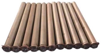
Both sides of the liquid storage tube are designed with stepped slots; one end is connected with sealing gasket, energy release plate and release tube, the other end is connected with liquid injection joint and heating pipe to form a high-pressure container filled with liquid carbon dioxide. The liquid storage tube is made of ultra-high strength steel and formed in one-step processing method. After high standard heat treatment process, the pressure bearing capacity of liquid storage tube can reach 1000 MPa. There are different types of liquid storage tubes, different filling volume of liquid storage tubes can be selected according to engineering operation requirement to achieve expectant blasting effect. Commonly parameters of CO2 blasting device are shown in Table 1.
Table 1Commonly parameters of CO2 blasting device
Model number | Length of liquid storage tube (mm) | Length of guide tube (mm) | Diameter of liquid storage tube (mm) | Internal volume (L) | Mass of liquid CO2 (g) |
51# | 1000 | none | 51 | 0.58 | 900 |
85# | 938 | 1500 | 83 | 1.57 | 1400 |
100# | 1520 | 1500 | 95 | 4.21 | 3500 |
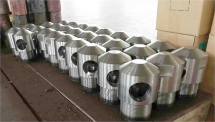
The release tube is made of special steel, one end of the release tube is open, and the other end is closed and connected with the liquid storage tube by thread. Symmetrical release holes are set on both sides of release tube, the release holes for coal mine is longer and more air outlets; the release holes for open-pit mine is shorter and the air outlets are usually set as two or four symmetrical outlets. After the crack initiation, the high-pressure air released from liquid storage tube can be ejected from release holes. By setting different types and numbers of release holes, the gas can be controlled along a fixed angle jet out and act on surrounding rock mass. The common type of release tube for open-pit mine is shown in Fig. 5.
Fig. 5The common type of release tube for open-pit mine
As shown in Fig. 6, the heating pipe is a device that provides heat energy for liquid carbon dioxide gasification in the liquid storage tube; the heating pipe is a special chemical activator cartridge, in which the wooden end at the bottom is equipped with a positive and negative bipolar bridge circuit. When the high energy pulse detonator is used for initiation, the electric current in the circuit reaches 0.8 A, the activating agent material produces chemical reaction and generates a large amount of heat, due to the endothermic effect, carbon dioxide will change from liquid state to gas state and supercritical state and then excite the fracturing system.
Fig. 6Heating pipe of CO2 blasting device
The energy release plate is a round steel plate, which is placed between the liquid storage tube and the release tube; energy release plate mainly plays the role of controlling peak pressure of gas released from the release tube. After the energy release plate reaches ultimate failure strength, high pressure carbon dioxide gas will be ejected from release hole of the release tube [31]. At the end of exhaust direction, the energy release plate plays a role of sealing liquid carbon dioxide under normal conditions; different fracturing performance is produced by changing thickness of energy release plate. The pressure sealing component should be used with sealing gasket to prevent the failing initiation of fracturing system caused by the air leakage. Fig. 7 shows the energy release plate and sealing gasket of CO2 blasting device.
The liquid storage tube is injected with liquid CO2, by activating the detonator, special chemicals in the heating pipe begin to react and a lot of heats could be released immediately. Liquid CO2 will rapidly vaporize with the volume expansion more than 600 times because of phase change, when the gas pressure in the liquid storage tube reach the limit strength of energy release plate, the energy release plate is break off, high pressure carbon dioxide enters the release tube and forms shock wave acting on the rock body.
Fig. 7The energy release plate and sealing gasket of CO2 blasting device
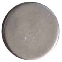
a) Energy release plate
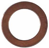
b) sealing gasket
3. Experimental scheme, instruments and process
3.1. Experimental scheme
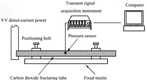
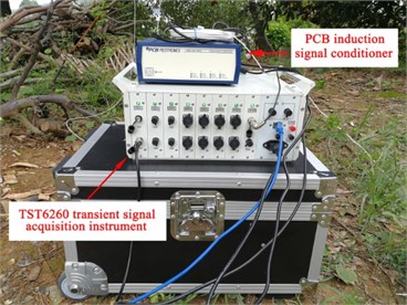
The experimental system for cavity pressure of carbon dioxide fracturing tube was established, as shown in Fig. 8, in which the carbon dioxide fracturing tube is restrained at the fixed trestle by using positioning bolt. The screw hole is drilled in advance at the lateral wall of fracturing tube through the numerical control thread lathe; the pressure sensor is installed at the lateral wall of the fracturing tube by means of threaded connection for measuring cavity pressure. The dynamic signal acquisition system for cavity pressure is composed of (1) explosion shock wave pressure 109C12 type sensor produced by PCB Electronics limited liability company, (2) TST 6200 transient signal acquisition instrument produced by Chengdu test limited company, (3) signal connecting line and (4) notebook computer, which can effectively collect the pressure change in fracturing tube during liquid carbon dioxide fracturing.
Fig. 8Schematic diagram of experimental system for cavity pressure
As shown in Fig. 9, the cavity pressure of type 85# liquid storage tube was tested by conducting out liquid carbon dioxide fracturing in the open field of Jingshan City, Hubei Province, China. In the daily production fracturing process, the length and outer diameter of type 85# liquid storage tube was 938 mm and 83 mm, respectively; the commonly used parameters is as follows: the mass of activating agent material is 250 g, the filling amount of liquid CO2 is 1.4 kg, and the thickness of energy release plate is 6 mm. In order to study the parameters influence of liquid CO2 filling amount, thickness of energy release plate and the mass of activating agent material on the cavity pressure, the mass range of activating agent material is 230-260 g, the mass range of liquid CO2 is 1.0-1.5 kg, and the thickness of energy release plate is 4-6 mm. A total of 10 cavity pressure tests of carbon dioxide fracturing tube have been carried out, the scheme parameters of cavity pressure tests of carbon dioxide fracturing tube are shown in Table 2.
Fig. 9Cavity pressure test of type 85# liquid storage tube
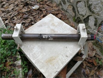
a) Installation diagram of pressure sensor
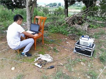
b) Field measurement process
Table 2Scheme parameters of cavity pressure tests of carbon dioxide fracturing tube
Serial number | Type of CO2 blasting device | Mass of activating agent material (g) | Mass of liquid CO2 (g) | Thickness of energy release plate (mm) |
1 | 85 | 230 | 1.3 | 6 |
2 | 85 | 230 | 1.1 | 6 |
3 | 85 | 245 | 1.1 | 4 |
4 | 85 | 245 | 1.3 | 4 |
5 | 85 | 245 | 1.5 | 4 |
6 | 85 | 245 | 1.0 | 6 |
7 | 85 | 245 | 1.1 | 6 |
8 | 85 | 260 | 1.2 | 6 |
9 | 85 | 230 | 1.2 | 6 |
10 | 85 | 230 | 1.2 | 4 |
3.2. Experimental instruments
3.2.1. Ultra-high speed dynamic signal acquisition instrument
High-speed gas in carbon dioxide fracturing tube belongs to ultra-high speed dynamic signal, the instantaneous variation of test signal is large and the amplitude in different stages is more than 10 times, in addition, the fracturing signal coexists with small amplitude gradual change signal. In the process of carbon dioxide cavity pressure test, the selection of test instruments should be based on the temperature, humidity, peak value and duration of pressure curve, whether there are interference signals in the measurement process, the economy and applicability of test instruments; carbon dioxide fracturing testing system should have requirements as follows:
(1) The test system has high dynamic response accuracy, good sampling frequency response characteristics, and good applicability for ultra-dynamic instantaneous signal to accurately measure the cavity pressure signal in the process of carbon dioxide fracturing.
(2) The internal components and mechanical shell of test system have strong impact and high temperature resistance to adapt working requirements of special environment.
(3) The test system has good economy and relatively low cost to meet the need of large-scale and batch use. At the same time, test process has easy operability and high reliability.
(4) The supporting software of test system can accurately set acquisition channel and parameters, automatically record blasting signal, and conveniently store signal data.
In the cavity pressure test of carbon dioxide fracturing tube, TST6260 transient signal acquisition instrument was adopted as ultra-dynamic dynamic signal acquisition instrument in order to completely measure cavity pressure curve in the process of carbon dioxide fracturing. The pressure shock wave 109C12 type sensor can only communicate with PCB induction signal conditioner after power supply and signal processing, the PCB induction signal conditioner has many functions, such as accurately compensating temperature error of pressure sensor, effectively amplifying signal of pressure sensor, and directly controlling the calibration process. TST6260 transient signal acquisition instrument and PCB induction signal conditioner are shown in Fig. 10.
Fig. 10TST6260 transient signal acquisition instrument and PCB induction signal conditioner
The trigger mode of liquid carbon dioxide phase change fracturing test system has an important influence on the complete measurement of cavity pressure curve in the process of carbon dioxide fracturing. TST6260 transient signal acquisition instrument has four triggering modes:
(1) Internal trigger: according to the magnitude of signal to start the acquisition, it is easy to set trigger channel, trigger level (percentage of range) and signal edge characteristics (rising edge, falling edge) to determine whether to internal trigger.
(2) External trigger: by setting the “external trigger” channel and giving the “external trigger” channel voltage at + 3.3 V ~ + 12 V positive pulse level signal, the purpose of trigger acquisition signal can be achieved.
(3) Manual trigger: it is mainly used for debugging or observing cycle signals; it is manually operated to send the start acquisition command through mouse or keyboard. If the trigger controllability is not strict, there is the phenomenon of false trigger or missing signal.
(4) Full channel trigger: set relatively independent trigger conditions for all channels and start acquisition when any channel signal meets the set trigger requirements.
TST6260 transient signal acquisition instrument channel bridge voltage adopts sensor excitation power supply. Each channel is independent and has a variety of channel types such as voltage, charge, ICP type, which can measure a lot of physical parameters such as pressure, strain, velocity, acceleration. The channel type is related to the hardware conditioning module, which can realize automatic identification function. During the test, the measurement range can be set according to the output amplitude of pressure sensor; the maximum signal amplitude in the measurement range of 50 %~90 % is feasible. For the tested signal, TST6260 transient signal acquisition instrument can realize low-pass filtering, high-pass filtering and band-pass filtering. In addition, the ultra-dynamic acquisition instrument has the function of sampling delay. The data length (sample number) needs to be recorded before the trigger point. The trigger time is defined as 0 time, the trigger time is negative before strike. In general, the data length of negative delay is –1 K ~ –10 k when adopt the internal trigger collects the transient signal.
TST6260 transient signal acquisition instrument adopts high strength aluminum alloy case; the highest transient sampling frequency can reach 20 MHz. Each channel has an independent DSP processor and A/D converter; the comprehensive measurement accuracy can reach ± 0.1 %, each channel adopts 14 bit A/D converter, the power supply mode adopts alternating current 220 V / 50 Hz and direct current 12 V, the excitation adopts constant voltage excitation: 2 V, 4 V, 6 V and 8 V; the measurement range is ± 2.5 MV ~ ± 5 V, the signal input mode adopts one side/ differential voltage, charge and ICP; in addition, the acquisition module has 16 channels and can set up multi-channel forms such as pressure acquisition channel, strain acquisition channel and temperature acquisition channel. According to the measurement scheme, the strain stress measurement of whole bridge, half bridge and 1/4 bridge can be easily complete. Equipped with corresponding sensor, high speed pressure, vibration and shock signal measurement can be accurately realized.
It can be seen from the above technical performance indexes that TST6260 transient signal acquisition instrument can excellently meet the cavity pressure test accuracy requirements of carbon dioxide fracturing tube.
3.2.2. Shock wave pressure sensors
In the process of carbon dioxide fracturing, the endothermic expansion of liquid carbon dioxide in the liquid storage tube will form a test environment with low temperature, high pressure and large transient pressure, which puts forward high requirements for the low temperature resistance, high pressure resistance and high frequency response parameters of pressure sensor. In this paper, referring to the shock explosion test literature and the manufacturer's shock wave pressure sensor parameter specification, the 109c12 type pressure sensor produced by American PCB electronics limited liability Company is finally selected. The 109c12 type pressure sensor has good working adaptability with high pressure resistance, low temperature resistance, good liquid insulation to water, and high frequency response accuracy, which can excellently meet the test requirements. Fig. 11 is the physical picture and structural diagram of 109c12 type pressure sensor.
Fig. 11Physical picture and structural drawing of 109C12 type pressure sensor
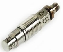
a) Physical picture
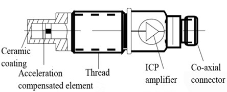
b) Structural drawing
The performance parameters of 109c12 type pressure sensor are shown in Table 3. 109c12 type pressure sensor is a kind of piezoelectric pressure sensor, which is packaged with epoxy resin and can measure tiny pressure fluctuation under high static pressure. It is a unique characteristic of piezoelectric pressure sensor, which has a wide linear measurement range and can be appropriately used for dynamic pressure measurement. Built in microcircuit and diaphragm with integrated ceramic coating, the response time reaches microsecond level; Rated range pressure is 0.690 Pa ~ 690 MPa, resonance frequency is ≥ 400 kHz, working temperature is –73℃ ~ +135℃; It is especially suitable for all kinds of dynamic pressure measurement, such as pneumatic pressure fluctuation, closed bomb combustion and explosion shock wave measurement.
It can be seen from above description of performance parameter in Table 3 that the 109c12 type pressure sensor has good structure and testing performance, which can be effectively applied to the pressure curve measurement requirements for high pressure gas of carbon dioxide fracturing tube.
Table 3Performance parameter of 109C12 type pressure sensor
Performance index | Parameter |
Measurement range | 690 MPa |
Maximum pressure | 862 MPa |
Sensitivity | 0.01 mv/KPa |
Resolution | 13.8 KPa |
Resonant frequency | ≥ 400 KHz |
Rise time | ≤ 2 µsec |
Non-linearity | ≤ 2 %FS |
Acceleration sensitivity | 0.015 KPa/(m/s2) |
Temperature range (operating) | –73℃ ~ +135℃ |
Temperature coefficient of sensitivity | ≤ 0.126 %/℃ |
Sensing geometry | Compression |
Sensing element | Quartz |
Housing material | C-300 Special high nickel alloy steel |
Diaphragm coating | Ceramic |
Sealing | Epoxy resin |
3.3. Experimental process
The test process on cavity pressure of carbon dioxide fracturing tube is as follows:
(1) Before the test, the 109c12 type pressure sensor was drilled in advance through the lathe and fixed into the carbon dioxide fracturing tube through threaded connection to measure the gas pressure during the fracturing process.
(2) The activating agent material and energy release plate are installed in the fracturing tube, then, the liquid carbon dioxide is filled in the liquid storage tube; the fracturing tube is installed on the fixed trestle to prevent the flying tube from injuring people after the fracturing is detonated.
(3) Connect the test wire, set the acquisition parameters and channel parameters: sampling frequency is set to 1 MHz, sampling length is set to 4 M, trigger mode is internal trigger, trigger edge is rising edge, trigger voltage is set to 1 % FS; channel parameters are set to pressure channel.
(4) When the high energy pulse detonator button is pressed, the high-pressure current causes the chemical reaction of activating agent material in the fracturing tube, the liquid carbon dioxide expands to form gaseous state and supercritical fluid state, resulting in the destruction of energy release plate, the high-pressure carbon dioxide is vented from the release hole at both ends of release tube to form a high-pressure gas jet.
(5) In the process of fracturing blasting, DAP software can be set to automatically save data, after the completion of fracturing blasting, the collected sample data can be displayed and the image post-processing operation is performed by using DAP software.
4. Experimental results and analyses
In the process of carbon dioxide fracturing blasting, in order to improve the power of liquid carbon dioxide phase change fracturing technology, the pressure response characteristics of liquid carbon dioxide blasting system were studied.
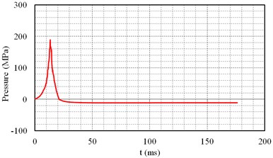
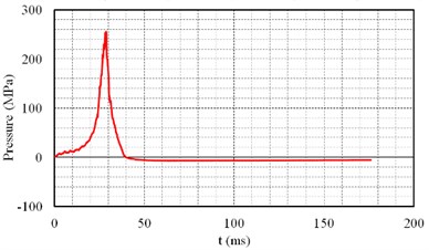
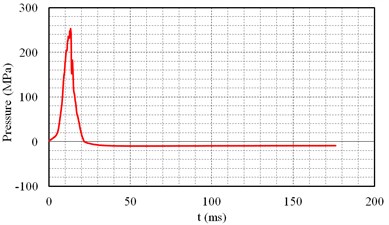
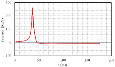
The cavity pressure of carbon dioxide fracturing device with different carbon dioxide mass, activator mass and thickness of energy release plate were tested by high-pressure dynamic testing equipment, the pressure distribution and variation law after CO2 gasification were obtained. A total of 10 cavity pressure tests were carried out on site, the cavity pressure curve of carbon dioxide fracturing device is obtained as shown in Fig. 12, the data parameters of cavity pressure test curve are shown in Table 4.
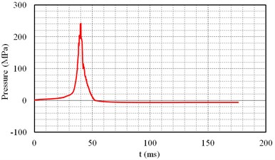
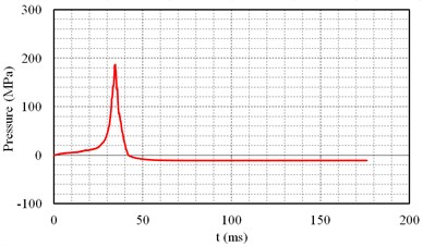
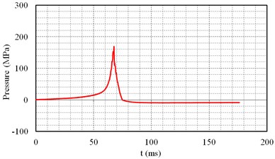
Fig. 12Cavity pressure curve of carbon dioxide fracturing tube
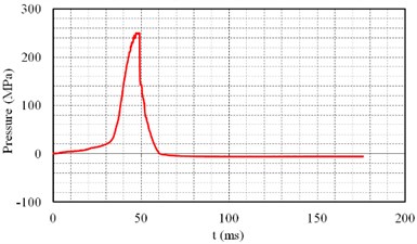
a) Serial number 1
b) Serial number 2
c) Serial number 3
d) Serial number 4
e) Serial number 5
f) Serial number 6
g) Serial number 7
h) Serial number 8
i) Serial number 9
j) Serial number 10
Table 4Data parameters of cavity pressure test curve
Serial number | Mass of activating agent material (g) | Thickness of energy release plate (mm) | Mass of liquid CO2 (g) | Peak pressure (Mpa) | Duration of positive pressure (ms) | Peak pressure arrival time (ms) |
1 | 230 | 6 | 1.3 | 249.8 | 60.3 | 46.9 |
2 | 230 | 6 | 1.1 | 240.6 | 52.0 | 39.7 |
3 | 245 | 4 | 1.1 | 186.8 | 41.9 | 34.2 |
4 | 245 | 4 | 1.3 | 169.1 | 74.8 | 67.7 |
5 | 245 | 4 | 1.5 | 188.7 | 21.1 | 13.2 |
6 | 245 | 6 | 1 | 255.7 | 39.8 | 28.3 |
7 | 245 | 6 | 1.1 | 253.2 | 21.7 | 13.3 |
8 | 260 | 6 | 1.2 | 260.2 | 45.5 | 37.0 |
9 | 230 | 6 | 1.2 | 259.8 | 71.0 | 60.1 |
10 | 230 | 4 | 1.2 | 184.0 | 62.0 | 52.3 |
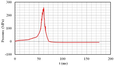
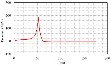
As can be seen from Fig. 12 and Table 4, the peak pressure in the carbon dioxide fracturing tube ranges from 169.1 to 260.2 MPa, the duration of positive pressure ranges from 21.1 to 74.8 ms and the peak pressure arrival time ranges from 13.2 to 67.7 ms. The peak pressure of blasting hole wall of explosive is 1~10 GPa and the peak pressure arrival time is 10~150 us [32-34], this indicates that there is a great difference between carbon dioxide fracturing blasting and explosive blasting.
Fig. 13Typical high pressure gas curve in the process of CO2 fracturing blasting
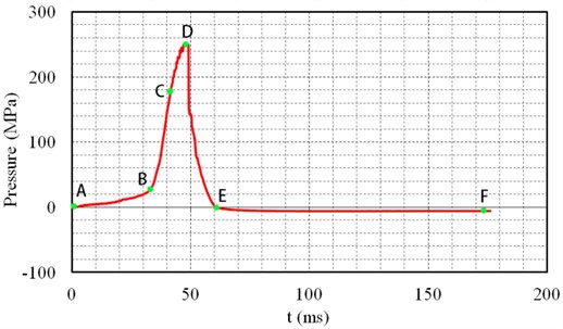
As shown in Fig. 13, the cavity pressure curve of No. 1 carbon dioxide fracturing test is selected as the typical high pressure carbon dioxide gas curve for analysis. It can be seen that after igniting the liquid carbon dioxide fracturing tube, the pressure rise slowly, then increases sharply and decays rapidly, in which the peak pressure arrival time is 46.9 ms; the gasification release time of liquid carbon dioxide is about 60.3 ms; When the pressure reaches the yield pressure limit of energy release plate, the energy release plate will be destroyed and high pressure gas will be released rapidly. The whole fracturing process of liquid carbon dioxide has gone through five stages.
(1) In the AB phase, the pressure increases slowly and the curve is concave upward with a time interval of 32.0 ms. Chemical reaction occurs after ignition and begins to transfer heat to liquid carbon dioxide medium. At this time, a part of carbon dioxide in the tube is gasified and gas-liquid coexistence state appears. This stage is a chemical reaction that releases heat from activating agent material, so the pressure rises slowly.
(2) In the BC phase, the pressure curve is close to a straight line and the time interval is 8.4 ms, in which the pressure and time show a linear relationship. This stage indicates that the chemical reaction stage of activating agent material is over, the carbon dioxide is rapidly absorbing external energy and the pressure rise rate is accelerated.
(3) In the CD phase, the curve deviates from linearity and presents a slow upward trend with a time interval of 6.5 ms, indicating that supercritical carbon dioxide enters into the stable gasification process and finally reaches peak pressure in the fracturing tube, which is the ultimate strength value of energy release plate.
(4) In the DE phase, the high pressure gas is released when the energy release plate is broken. The high pressure gas is ejected from the air outlet to form a shock wave impacting surrounding rock mass, which produces a fracture zone and some initial orientation fractures controlling the subsequent fracture expansion, the subsequent high pressure gas wedge into the crack formed in the crack tip stress concentration by stress wave. The stress wave continues to attenuate into seismic wave forming blasting vibration zone in the far area of fracturing hole. The gas pressure decreased sharply with an interval time of 13.4 ms.
(5) In the EF phase, the pressure varies from negative pressure to normal atmospheric pressure. Due to the rapid release of gas, the pressure in the tube decays rapidly. At this time, the decay rate of pressure is greater than the growth rate of pressure; therefore, the phenomenon of negative pressure in the tube appears. It takes about 500~1000 ms to recover to atmospheric pressure.
In pressure vessels, energy relief plate is often used to control overpressure relief. At present, there are three types of energy relief plate according to different structural planes: positive arch energy relief plate, reversed arch energy relief plate and circular plate energy relief plate [35].
The concave surface of positive arch energy relief plate is at the high pressure side of pressure system; in general, the positive arch energy relief plate will break due to tension. In the process of positive arch energy relief plate prepressing production and molding, the molding pressure control requirements are high and the machine processing is difficult, so it can't be widely used. The convex surface of reversed arch energy release plate is at the high pressure side of pressure system; due to compression instability, the reversed arch energy release plate turns over and breaks in the failure limit state; the value of burst pressure is affected by controlling the thickness and arch height of energy relief plate; when the thickness of energy relief plate is too large, reversed arch energy relief plate will not be destroyed immediately after instability and overturning, which leading to the potential safety injury; therefore, the reversed arch energy release plate is less used when the design value of burst pressure is high [36, 37]. The circular plate energy relief plate is processed by simple steel without prepressing in advance, which has many advantages such as low processing cost and simple structure, and has been widely used in the field of pressure vessel engineering [38].
At present, there is not a complete and accurate calculation formula for the pressure of energy release plate; semi empirical formula is commonly used. As shown in Eq. (1), the formula of welded flat head thickness in the design process of pressure vessel is as follows:
where is the structural characteristic coefficient (0.2 ~ 0.35), is the diameter of flat head, is the allowable stress of material, is the design pressure, and is the weld coefficient (0.6-1, determined according to the flaw detection situation and the form of the weld joint).
Refer to the formula of welded flat head to carry out the design calculation of energy release plate; the parameters of Eq. (1) are processed as follows:
(1) The diameter of flat head is replaced by the diameter of release hole ;
(2) is the allowable stress of material after considering safety factor, where it is taken as the tensile strength of material .
(3) Structural characteristic coefficient is the lower limit, 0.2;
(4) The energy release plate is fixed in the tube through threaded structure gripper without welding seam, the welding coefficient is the upper limit, 1.
By transforming Eq. (1) and substituting corresponding symbols, Eq. (2) can be obtained as follows:
According to the tensile failure of first crack in the middle of positive arch energy relief plate, the calculating formula for thickness of energy release plate is shown in Eq. (3):
where is the design pressure, is the diameter of release hole, is the coefficient related to strain hardening degree of material, the value range of is 3 ~ 3.8, is the tensile strength of material.
The formula for calculating burst pressure according to Eq. (3) is shown in Eq. (4):
where the coefficient related to strain hardening degree of material is the lower limit, 3.0.
In view of the shear failure of positive arch energy release plate, the rupture mode of energy release plate is that energy release plate is sheared along the edge of safety valve body, the blasting pressure is set as , the radius of the release hole is , the material shear strength is , we can find that:
By transforming Eq. (5), the formula of bursting pressure can be obtained as shown in Eq. (6):
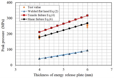
Type 85# carbon dioxide fracturing tube is used in cavity pressure test, the steel type of energy relief plate is 45 carbon steel, the tensile strength of 45 carbon steel is 600 MPa, shear strength is 0.6 ~ 0.7 times of tensile strength and 380 MPa can be taken as shear strength, the diameter of release hole is 34 mm. According to Eq. (2), Eq. (4), Eq. (6) and material mechanical property data, the calculated value, test value and ratio of peak cavity pressure for carbon dioxide fracturing device are shown in Table 5.
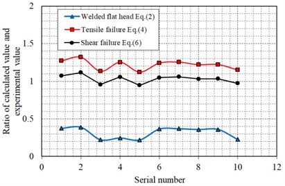
Fig. 14 shows the comparison curve between the calculated and experimental values of peak cavity pressure for carbon dioxide fracturing tube. It can be seen from Table 5 and Fig. 14 that the experimental values of peak cavity pressure are close to calculated results of the shear failure Eq. (6), at the same time, the experimental values of peak cavity pressure are significantly larger than calculated results of welded flat head Eq. (2) and slightly lower than calculated results of the tensile failure Eq. (4); According to the welded flat head Eq. (2), tensile failure Eq. (4) and shear failure Eq. (6), the ratio of calculated peak pressure value and experimental value ranges from 0.22 to 0.39, from 1.12 to 1.32 and from 0.95 to 1.11, respectively; which indicates that the welded flat head Eq. (2) severely underestimates the peak cavity pressure in the carbon dioxide fracturing device, conversely, the tensile failure Eq. (4) slightly overestimated the peak cavity pressure; the shear failure Eq. (6) can accurately reflect the peak cavity pressure of the fracturing tube. When the cavity pressure reaches the failure strength of material, most of energy release plate first shear failure along the edge of safety valve body and a few of energy release plate first tensile failure due to the difference of material mechanical properties, which is consistent with the failure pattern of energy release plate observed in the cavity pressure test.
Table 5The calculated value, test value and ratio of peak pressure for cavity pressure
Serial number | Thickness of energy release plate (mm) | Test value of peak pressure (MPa) | Welded flat head Eq. (2) | Tensile failure Eq. (4) | Shear failure Eq. (6) | |||
Calculated value (MPa) | Ratio | Calculated value (MPa) | Ratio | Calculated value (MPa) | Ratio | |||
1 | 6 | 249.8 | 93.4 | 0.37 | 317.6 | 1.27 | 268.2 | 1.07 |
2 | 6 | 240.6 | 93.4 | 0.39 | 317.6 | 1.32 | 268.2 | 1.11 |
3 | 4 | 186.8 | 41.5 | 0.22 | 211.8 | 1.13 | 178.8 | 0.96 |
4 | 4 | 169.1 | 41.5 | 0.25 | 211.8 | 1.25 | 178.8 | 1.06 |
5 | 4 | 188.7 | 41.5 | 0.22 | 211.8 | 1.12 | 178.8 | 0.95 |
6 | 6 | 255.7 | 93.4 | 0.37 | 317.6 | 1.24 | 268.2 | 1.05 |
7 | 6 | 253.2 | 93.4 | 0.37 | 317.6 | 1.25 | 268.2 | 1.06 |
8 | 6 | 260.2 | 93.4 | 0.36 | 317.6 | 1.22 | 268.2 | 1.03 |
9 | 6 | 259.8 | 93.4 | 0.36 | 317.6 | 1.22 | 268.2 | 1.03 |
10 | 4 | 184.0 | 41.5 | 0.23 | 211.8 | 1.15 | 178.8 | 0.97 |
Fig. 14Comparison curve between the calculated and experimental values of peak cavity pressure
a) Calculated value and experimental value
b) Ratio of calculated value and experimental value
5. Conclusions
The cavity pressure test of carbon dioxide fracturing tube under different parameters of carbon dioxide quantity, activator quantity and thickness of energy release plate is carried out. The relation curve between pressure and time in the liquid CO2 fracturing tube was effectively measured and the variation law of pressure curve was analyzed. This paper attempts to establish the formula relationship between the peak cavity pressure and the thickness of energy release plate for carbon dioxide fracturing tube. The welded flat head formula, tensile failure formula and shear failure formula are used to calculate the peak cavity pressure of carbon dioxide fracturing tube, in which the calculated results are compared with the measured values. The main conclusions are drawn as follows:
(1) This paper introduces in detail the scheme and steps of cavity pressure test of carbon dioxide fracturing tube, puts forward the requirements of test system for measuring the ultra-high speed dynamic signal and points out that the performance parameters of TST6200 transient signal acquisition instrument and 109c12 type blasting shock wave sensor can meet the test requirements.
(2) After igniting the liquid carbon dioxide fracturing tube, the cavity pressure rise slowly, then increases sharply and decays rapidly, when the pressure reaches the yield pressure limit of energy release plate, the energy release plate will be destroyed and high pressure gas will be released rapidly. The peak pressure in the carbon dioxide fracturing tube ranges from 169.1 to 260.2 MPa, the duration of positive pressure ranges from 21.1 to 74.8 ms, and the peak pressure arrival time ranges from 13.2 to 67.7 ms. The peak pressure of blasting hole wall of explosive is 1~10 GPa and the peak pressure arrival time is 10~150 us, this indicates that there is a great difference between carbon dioxide fracturing blasting and explosive blasting.
(3) The welded flat head formula severely underestimates the peak cavity pressure, conversely, the tensile failure formula slightly overestimated the peak cavity pressure; the shear failure formula can accurately reflect the peak cavity pressure of the fracturing tube. When the cavity pressure reaches the failure strength of material, most of energy release plate first shear failure along the edge of safety valve body and a few of energy release plate first tensile failure due to the difference of material mechanical properties, which is consistent with the failure pattern of energy release plate observed in the cavity pressure test. The cavity pressure of carbon dioxide fracturing tube can be precisely control by using different thickness energy release plate.
References
-
G. Hu, W. He, and M. Sun, “Enhancing coal seam gas using liquid CO2 phase-transition blasting with cross-measure borehole,” Journal of Natural Gas Science and Engineering, Vol. 60, No. 1, pp. 164–173, Dec. 2018, https://doi.org/10.1016/j.jngse.2018.10.013
-
X. Yang et al., “Environmentally friendly techniques for high gas content thick coal seam stimulation-multi-discharge CO2 fracturing system,” Journal of Natural Gas Science and Engineering, Vol. 61, No. 1, pp. 71–82, Jan. 2019, https://doi.org/10.1016/j.jngse.2018.11.006
-
H. Chen, Z. Wang, X. Chen, X. Chen, and L. Wang, “Increasing permeability of coal seams using the phase energy of liquid carbon dioxide,” Journal of CO2 Utilization, Vol. 19, No. 3, pp. 112–119, May 2017, https://doi.org/10.1016/j.jcou.2017.03.010
-
W. He, F. He, K. Zhang, Y. Zhao, and H. Zhu, “Increasing permeability of coal seam and improving gas drainage using a liquid carbon dioxide phase transition explosive technology,” Advances in Civil Engineering, Vol. 2018, No. 1, pp. 1–15, Aug. 2018, https://doi.org/10.1155/2018/3976505
-
J. Kang, F. Zhou, Z. Qiang, and S. Zhu, “Evaluation of gas drainage and coal permeability improvement with liquid CO2gasification blasting,” Advances in Mechanical Engineering, Vol. 10, No. 4, p. 168781401876857, Apr. 2018, https://doi.org/10.1177/1687814018768578
-
H. Yan, J. Zhang, N. Zhou, and M. Li, “Staged numerical simulations of supercritical CO2 fracturing of coal seams based on the extended finite element method,” Journal of Natural Gas Science and Engineering, Vol. 65, No. 1, pp. 275–283, May 2019, https://doi.org/10.1016/j.jngse.2019.03.021
-
Y. Zhang, J. Deng, H. Deng, and B. Ke, “Peridynamics simulation of rock fracturing under liquid carbon dioxide blasting,” International Journal of Damage Mechanics, Vol. 28, No. 7, pp. 1038–1052, Jul. 2019, https://doi.org/10.1177/1056789518807532
-
Y. Q. Zeng et al., “Research on time-frequency characteristics for blasting vibration signal of CO2 blasting by frequency slice wavelet transform,” Engineering Letters, Vol. 28, No. 4, pp. 1047–1057, 2020.
-
Y. Y. Huang, C. X. Tang, and L. L. Yin, “Development on fast filling system of carbon dioxide fracturing facility,” (in Chinese), Coal Mine Machinery, Vol. 36, No. 7, pp. 114–115, 2015.
-
Y. Y. Huang, L. L. Yin, and H. Ni, “Development and application of carbon dioxide fracturing device,” (in Chinese), Coal Technology, Vol. 34, No. 8, pp. 123–124, 2015.
-
G. Q. Wu, “Degree of safety test of carbon dioxide fracturing device,” (in Chinese), Coal Mine Blasting, Vol. 23, No. 6, pp. 5–6, 2016.
-
G. Q. Wu and L. Zhang, “Analysis of reliability and safety actors of carbon dioxide fracturer,” (in Chinese), Coal Mine Blasting, Vol. 38, No. 7, pp. 48–49, 2017.
-
C. Chen et al., “The analysis of reliability and safety actors of carbon dioxide fracturer,” (in Chinese), Coal Mine Blasting, Vol. 24, No. 4, pp. 13–15, 2017.
-
“Safety Technical Requirements for Carbon Dioxide fracturing device,” (in Chinese), Mining Products Safety Approval and Certification Center Co., GG2014021, 2014.
-
Z. J. Hong, C. Wang, and Z. Q. Xiong, “Research on CO2 phase-transition fracturing technology for permeability improvement in high gas and low permeability coal seam,” (in Chinese), Journal of Safety Science and Technology, Vol. 13, No. 1, pp. 39–45, 2017.
-
H. D. Chen, Z. F. Wang, L. L. Qi, and F. H. An, “Effect of liquid carbon dioxide phase change fracturing technology on gas drainage,” Arabian Journal of Geosciences, Vol. 10, No. 14, pp. 1–9, Jul. 2017, https://doi.org/10.1007/s12517-017-3103-0
-
T. Lu, Z. Wang, H. Yang, P. Yuan, Y. Han, and X. Sun, “Improvement of coal seam gas drainage by under-panel cross-strata stimulation using highly pressurized gas,” International Journal of Rock Mechanics and Mining Sciences, Vol. 77, No. 1, pp. 300–312, Jul. 2015, https://doi.org/10.1016/j.ijrmms.2015.03.034
-
Q. Li, D. Luo, G. Feng, H. Ma, X.A. Wei, and G. Chen, “Dynamic characteristics of liquid CO2 phase change fracturing, using experimental technique,” Geotechnical and Geological Engineering, Vol. 37, No. 4, pp. 3387–3398, Aug. 2019, https://doi.org/10.1007/s10706-019-00853-w
-
X. S. Huang, F. L. Zhang, and Z. Zhang, “Study on application of CO2 fracturing apparatus in pre-splitting blasting of rock deep hole,” (in Chinese), Blasting, Vol. 34, No. 3, pp. 131–135, 2017.
-
X. H. Zhou, J. L. Men, and D. P. Song, “Research on optimal borehole parameters of antireflection in coal seam by liquid CO2 blasting,” (in Chinese), Chinese Journal of Rock Mechanics and Engineering, Vol. 35, No. 3, pp. 524–529, 2016.
-
Q. X. Dong et al., “Research on TNT equivalent of liquid CO2 phase-transition fracturing,” (in Chinese), China Safety Science Journal, Vol. 24, No. 11, pp. 84–88, 2014.
-
K. M. Sun et al., “Mechanism of fracture caused by supercritical CO2 explosion under the impact of initial stress,” (in Chinese), Chinese Journal of Solid Mechanics, Vol. 38, No. 5, pp. 473–482, 2017.
-
G. J. Liu et al., “Experimental study on the supercritical CO2 fracturing of shale,” (in Chinese), Journal of China Coal Society, Vol. 42, No. 3, pp. 694–701, 2017.
-
J. Z. Su, F. X. Li, and T. Zhou., “Hydraulic fracture propagation behaviors and geometry under supercritical CO2 fracturing in shale reservoirs,” (in Chinese), Oil and Gas Geology, Vol. 40, No. 3, pp. 616–625, 2019.
-
S. C. Zhu, H. F. Zhou, and H. D. Li, “The application of carbon dioxide gun in processing hanging arch at triangle area of fully mechanized mining face roadway,” (in Chinese), Safety in Coal Mine, Vol. 44, No. 8, pp. 144–146, 2013.
-
G. Wei et al., “Test research on coal drop with liquid CO2 Blaster,” (in Chinese), Journal of Mining and Strata Control Engineering, Vol. 14, No. 1, pp. 22–24, 2009.
-
H. D. Wei, “Application of carbon dioxide pre-split blasting forced caving technique in 80124 fully mechanized face,” (in Chinese), Shandong Coal Science and Technology, Vol. 24, No. 8, pp. 70–71, 2017.
-
X. G. Hao, “Design and research the test system aimed at the liquid carbon dioxide blast pre-splitting in low permeability coal seam,” M.S. thesis, North University of China, Taiyuan, China, 2016.
-
Y. B. Han, “Mechanism research on increase coal gas permeability by liquid CO2 phase transition fracturing technique,” M.S. thesis, Henan Polytechnic University, Jiaozuo, China, 2014.
-
X. F. Xie et al., “Research and review about the liquid CO2 phase-transforming rock fracturing technology,” (in Chinese), Journal of Railway Science and Engineering, Vol. 15, No. 6, pp. 1406–1414, 2018.
-
X. M. Sun, “Research on strengthening gas pre-drainage effect with the fracturing technique by liquid CO2 phase transition in layer through boring,” M.S. thesis, Henan Polytechnic University, Jiaozuo, China, 2014.
-
X. Xia et al., “Numerical simulation of blast-induced cracks in rock,” (in Chinese), Rock and Soil Mechanics, Vol. 27, No. 11, pp. 1987–1991, 2006.
-
Q. Y. Chen, “Research on damage property of rock mass under different blasting conditions,” Ph.D. Thesis, Institute of Rock and Soil Mechanics, Chinese Academy of Sciences, Wuhan, China, 2019.
-
M. Chen et al., “Calculation methods for peak pressure on borehole wall of contour blasting,” (in Chinese), Explosion and Shock Waves, Vol. 39, No. 6, pp. 103–112, 2019.
-
Y. Sun, “Design of heavy-calibre rupture disks,” (in Chinese), Pipeline Technique and Equipment, Vol. 18, No. 3, pp. 57–59, 2011.
-
X. M. Gu, Q. L. Wu, and X. X. Yang, “Bursting mechanism of domed annular-slotted bursting discs,” (in Chinese), Journal of East China University of Science and Technology, Vol. 30, No. 1, pp. 99–102, 2004.
-
Y. J. Zhu, G. F. Gao, and X. W. Ding, “A study of bulging characteristics of circular slotted plane rupture discs,” (in Chinese), Petro-Chemical Equipment, Vol. 34, No. 5, pp. 28–31, 2005.
-
T. M. He, “Research on performance of rupture disk used for breathing apparatus cylinder,” (in Chinese), Mining Safety and Environmental Protection, Vol. 42, No. 4, pp. 83–86, 2015.
Cited by
About this article

The study was supported by the Key Program of National Natural Science Foundation of China (Grant No. 51439008), National Natural Science Foundation of China (Grant Nos. 41572307 and 51779248), and The Program of Hunan Province Education Department (Grant No. 19C0870).
