Abstract
This paper presents a novel pneumatic Down-The-Hole (DTH) hammer with self-rotation bit used for rock drilling, and the mechanical structure and working principle are mainly covered. A unique mechanism with ratchet and pawl incorporated in pneumatic DTH hammer is proposed for percussion-rotation drilling to break rock. The drill bit can rotate while the drill pipe stays still because of the structure design and reduces the friction between the drill pipe and borehole. Firstly, the rationality of mechanical invention is verified via the finite-element software ANSYS and the numerical simulation of impact dynamics. Moreover, the energy transfer regulation is revealed in the impact process under differential final impact velocity, which can help practical experience in mechanical design. Finally, based on the experimental study on the novel hammer, we found that its function can satisfy the requirement, as well as overall performance, was improved.
1. Introduction
Pneumatic DTH drilling is a rotary percussive drilling method widely used in many fields such as infrastructure construction [1], geological exploration [2], oil and gas production [3], etc. It has many advantages: less power loss, higher penetration rate, and greater hole accuracy, especially in hard rock formations [4-7]. Conventional pneumatic DTH hammer driven by compressed air provides a specific impact frequency and energy to drill bit in stress waves for rock breaking. The hammer is located behind the drilling bit in the DTH drilling, and the drill rig provides rotary torque and axial pressure to drill pipe, and the drill pipe is simultaneously pushed down and forced to rotate with the hammer [8]. It might result in increased friction and disturbed hole wall and limit the application of DTH hammers for horizontal and directional drilling. To improve the performance and application effect of the DTH hammer, many scholars have carried out theoretical and experimental research, especially on motion mechanisms and mechanical structures. Chiang et al. developed a non-linear dynamic model consisting of six differential equations to compute the performance of valveless DTH pneumatic hammers [8]. Based on the finite element method, Liu et al. analyzed the rock breaking and penetration rate (ROP) rise mechanism of rotary percussive cutting [9]. Kim et al. developed a pneumatic dynamic model of DTH hammer to predict drilling performance and validated the model through laboratory tests [10, 11]. Meng et al. solved the problem of reasonable deviation and improved drilling efficiency by using the KQC series of air hammers [12]. Bu et al. analyzed the impact performance and the phenomenon of the drill string's axial forced vibration with a periodic impacting force using ANSYS software [13, 14]. Depouhon et al. presented a dynamical model that integrates the axial dynamics of elastic piton and drill bit and analyzed the percussive drilling system [15].
The application of the DTH hammer in the vertical section of drilling fields has confirmed that it can improve drill efficiency and reduce borehole deviation compared with rotary drilling. However, many technical problems persist in directional and horizontal drilling, such as high friction and rotary table driving difficulty. The authoritative publication “Air and Gas Drilling Manual” stated that the Pneumatic DTH hammer has only been applied in vertical drilling. Zhao et al. verified that the adequate power and drilling rate would decline with the increase of devotion angle [16]. From the above, although these scholars have done the preliminary research, they only conducted the working mechanism and structural optimization of the conventional DTH hammer. We designed a novel DTH hammer, which combined the advantages of a pneumatic rock drill, adequately utilized the energy of returning piston's stroke, and achieved self-rotation of the drill bit. The structure of the novel hammer was optimized by finite element theory, and a test device verifies the feasibility.
This study redesigns the air distributor, special-purpose piston, and rotation joint. The principle of the ratchet mechanism was introduced to realize the separate motions of drill pipe and bit. Thus, when the high-pressure gas is input, the hammer can rotate while the drill pipe is static without a drilling rig. The self-motion of the drill bit can reduce the friction force of drill string and improve the quality of the borehole, the stiffness of the drill pipe, and the efficiency of breaking rocks. It makes a great significance to geological explorations and engineering constructions.
2. Working principle of Pneumatic DTH Hammer with Self-rotation bit
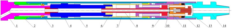
Conventional pneumatic DTH hammer consists of valvetrain, check valve, cutting removal mechanism, preventing striking vainly mechanism, and bit hanger device. Besides that, the novel DTH hammer proposed in this paper includes a self-rotation bit mechanism. Fig. 1 shows the overall structure of the pneumatic DTH hammer with self-rotation bit. The core of its mechanism is to use the gas generated by the air compressor to drive the piston to strike the drill bit and convert the linear motion of the piston into the rotary motion of the drill bit in a limited space.
Fig. 1Structure diagram of pneumatic DTH hammer with self-rotation bit: 1 – drill bit; 2 – chuck; 3 – bit retainer ring; 4 – piston; 5 – hammer casing; 6 – nut; 7 – inner cylinder; 8 – helical rod; 9 – air distributor; 10 – thrust ball bearing; 11 – rotary joint; 12 – connector; 13 – check valve; 14 – top sub
2.1. Working principle
The rotation assembly includes a helical rod, a rotary joint, a connector, a piston fitted with a nut at the tail, and a ratchet mechanism. It combines the ratchet and the air distributor into one part (see Fig. 2). The head of the helical rod is equipped with pawls, while the tail ties in with the nut. The tail is milled with spiral teeth and forms a spiral pair with the nut, and pawls rest on the internal teeth of the ratchet under the action of tower springs. The ratchet mechanism has the characteristic of intermittent circular motion in one direction so that the ratchet can only rotate in one direction. The ratchet threaded with the hammer casing can drive the chuck and the drill bit to revolve together. The return stroke of the impact piston is used for anticlockwise rotation, and the working principle of the novel hammer is as follows.
At the beginning of the impact strike process, the piston and the check valve are extremely upper. The compressed air enters the annular space and the rear chamber through the radial hole of the inner cylinder and the air distributor, as shown in Fig. 3. Then the piston begins to move downward at high speed to impact the drill bit under pressure difference, and the air in the front chamber is discharged into the hole bottom. Since the nut fixed in the rear end of the piston is in a splined joint with the spiral rod, the latter will rotate clockwise to a certain degree with the ratchet mechanism while the nut is going down with the piston. At this moment, the pawls are turning along with the ratchet, and the spiral rod is in idling condition. The hammer casing and the drill bit are in the non-rotating stage.
Fig. 2Mechanism of self-rotation: 1 – piston; 2 – nut; 3 – helical rod; 4 – air distributor; 5 – ratchet wheel; 6 – tower spring; 7 – pawls
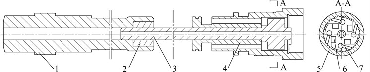
Fig. 3Impact stroke process. Notes: Red region is air inflow channel connected to air source and is high-pressure zone; Blue region is gas outflow channel connected to the hole bottom and is low-pressure zone

The central hole of the drill bit will be closed when the piston goes down, and the pressure in the front chamber starts to rise. The radial holes of the helical rod leave the piston, the rear chamber may communicate with the hole bottom. Meanwhile, the pressure reduces to the atmosphere. The piston strikes the drill bit at the end of the impact stroke, and the compressed air filled with the front chamber through the annular space between cylinder and casing and the air distributor, and then the piston starts to move upward, and the return stroke begins (see Fig. 4). In this process, the spiral rod will rotate counterclockwise to a certain degree with the ratchet mechanism, and the pawls hold the internal teeth of the ratchet. When the helical moment of the spiral rod is sufficient enough to overcome the resistance moment of the hammer case and rocks, pawls on the spiral rod drive the ratchet to move and make it rotate with the spiral rod to a certain degree. The ratchet is in a threaded joint with the hammer casing and is easy to achieve, and the hammer casing can drive the drill bit to rotate simultaneously and realize self-rotation motion.
Fig. 4Return stroke process

2.2. The design of the cutting removal mechanism
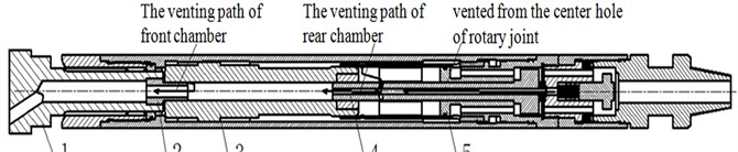
The cutting removal mechanism consists of an air distributor, a helical rod, a piston, a bit, and a tailpipe. The pressured gas is divided into two paths when it gets into the DTH hammer. One channel between the rotation joint and the check valve flows to the hole bottom directly through the central hole of the helical rod, the piston’s central hole, and the drill bit's vent hole. The other vents from the front chamber and gets through the vent hole of the drill bit, or vents from the rear chamber and gets through the vent hole of the helical rod, the central hole of the helical rod, the central hole of the piston, the vent hole of the drill bit. The function of this mechanism is to carry the rock cutting out of the hole and cooling the drill bit. The venting paths are shown in Fig. 5.
3. Impact dynamics analysis of DTH hammer
The pneumatic DTH drilling with self-rotation bit is also a rotary percussive drilling method. It has a concise duration, and its value can increase suddenly [17-18]. When the hammer is drilling hard rocks, it works with percussive drilling as the primary means and rotary drilling as supplemented. Impact load act on some surface of the part in a short time. Contact stress can quickly reach an extremely high value and generate the local stress concentration. Thus, the rock-crushing efficiency can be increased significantly [19-20].
Fig. 5The venting paths: 1 – drill bit; 2 – tailpipe; 3 – piston; 4 – helical rod; 5 – air distributor
The piston repeatedly impacts the drill bit at high speed with a specific frequency when the hammer is working. Under the alternative load, the piston may cause fatigue failure at stress focus. Common failures are crack, head metal peel, and head depression [20]. This paper uses ANSYS to analyze the impact dynamics of the piston and the drill bit and check the piston’s strength.
3.1. Primary hypothesis and governing equation
This paper focuses on the generation, transmission, and dissipation of stress waves in the two critical components of piston and drill bit and the stress change at each variable section through ANSYS software, regardless of the drilling effect of the drill bit. Therefore, the basic assumptions are as follows:
(1) Ignoring the process of shear rock breaking between bit and rock, and only consider the axial impact process;
(2) Ignoring the influence of dynamic load generated by the whole drill string system on the impact process of piston and bit is ignored;
(3) Remove the carbide tooth of the drill bit and simplify the chamfer and fillet of the piston and the drill bit.
The algorithm of the ANSYS program adopts the Lagrange formulation. When the piston collides with the bit in the DTH hammer, their contact is assumed to have no friction, and the governing equations are presented as follows [21]. if the element coordinates at the initial time are and the element coordinate is any time, we can get Then the motion equation of the particle are as follows:
When 0, the initial condition is:
where denotes the initial velocity.
Equation of mass conservation:
where represents the current density; represents the reference density; represents the Jacobian matrix.
Equation of momentum conservation:
where denotes the acceleration; denotes the Cauchy stress; denotes the body force density.
Equation of energy conservation used to calculate the total energy balance:
where presents the current volume; presents the strain rate tensor; and present the hydrostatic pressure and bulk viscosity, respectively, the deviatoric stresses is given by:
where denotes the Kronecker delta (1, if ; otherwise 0):
Based on the virtual work principle, Eq. (4) can express as the weak form of equilibrium equation [14]:
where fulfills all boundary conditions, and the integration is over the current geometry.
If the finite element technique is interconnected using a matrix form [14, 21], Eq. (8) becomes:
where is an interpolation matrix; is the stress vector; is the strain-displacement matrix; is the nodal acceleration vector; is the body force load vector, and is applied traction load.
This equation is integrated over time and used to calculate the state and global energy balance equations.
3.2. Finite element model and parameters
The analysis model of the novel DTH hammer is composed of piston and bit, and the piston is applied an initial velocity and the force down to strike the drill bit, as shown in Fig. 6. The SOLID164 unit was adopted to mesh the analysis model and define their contact area and critical parts during the calculating process.
Fig. 6Analysis model of the piston and the drill bit
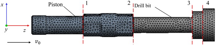
The piston and the drill bit were meshed by tetrahedron elements. The clearance between the piston and the drill bit is 2 mm, and this value does not affect the propagation effect of stress waves in the impact process. This analysis adopted the Johnson Holmquist model, which has a good performance in rock impact simulation analysis under high strain rates and large deformation. In addition, the physical properties of the piston and the drill bit are listed in Table 1 [22].
Table 1Material parameters of piston and drill bit
Part name | Materials type | Density (Kg/m3) | Elastic modulus (MPa) | Poisson ratio | Tensile strength (MPa) | Yield strength (MPa) |
Piston | 20CrMnTi | 7800 | 2.06E5 | 0.3 | 1080 | 850 |
Drill bit | 20Ni4Mo | 7800 | 2.10E5 | 0.27 | 1480 | 1220 |
4. Simulation results and discussion
The numerical analysis in the collision process calculated the equivalent stress and energy transfer in the piston and the drill bit under different final impact velocities and neglected the rock breaking effect and drilling efficiency problems. Therefore, the impact interface was set by surface to surface automatic contact. The static friction coefficient was set to 0.2, the dynamic friction coefficient was set to 0.1, and the viscous damping coefficient was set to 0.1. The total simulation time setting is 0.5 ms. The results analyzed the propagation process of stress wave, the energy loss caused by piston rebound, and the relationship between impact velocity and the maximum stress of piston and bit.
4.1. Propagation process of stress wave
When the piston strikes the drill bit, the impact energy propagates between the piston, the drill bit, and the rock in the form of stress wave. Part of the energy used in broken rock, another part of the energy in the form of stress wave transmitted back and forth between piston, drill bits, and rock. The incident wave and reflected wave easily cause stress concentration in some parts. In the long-term work, fatigue failure is easy to occur in some regions, so we selected four planes or variable cross-sections in the position and the drill bit as monitoring objects (see Fig. 6).
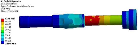
Fig. 7 shows the equivalent stress diagram of the piston and the bit at 175 μs. At this time, the reflected wave is transmitted to the piston's big end and the drill bit's tail and superimposed with the subsequent stress wave. The stress of the big end face of the piston reaches the maximum pressure of 305MPa in the whole collision process, and the stress at the tail of the drill bit comes to the maximum stress of 519 MPa.
Fig. 7Equivalent stress diagram of the piston and drill bit
4.2. Energy transfer analysis
Fig. 8 shows the velocity changed the curve of the piston during the process of impacting. When the piston strikes the drill bit at 6.5 m/s, the piston contacts with the drill bit at 75 μs, and the piston starts to slow down. The velocity of the piston reduces to 0 at 216 μs, and the piston begins to rebound. The maximum rebound velocity is around 3.5 m/s. The rebound coefficient is the ratio of piston rebound velocity to the last impacting speed of the piston, and its value is 0.54.
Fig. 8The velocity changed the curve of the piston
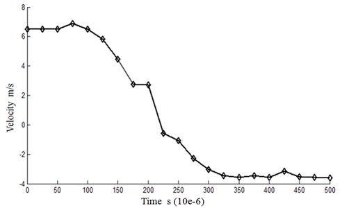
When the rebound coefficient is 0, all the energy of the impact is transmitted to the drill bit to break the rock, which is ideal. In actual working conditions, the rebound phenomenon of the piston is common, and the rebound coefficient is about 0~0.64. Generally, the incident wave is the critical cause of rebound.
Fig. 9 shows the equivalent stress curve during the collision between the piston and the drill bit. The analysis indicates that the stress on the contact surface between the piston and the drill bit reaches the extremum in the whole collision process. The piston stress gets the maximum value of 304 MPa at 175 μs. The fatigue failure of the contact surface between the piston and drill bit will be the leading cause of piston failure.
In actual working, the repeated impact will form fatigue concave on the contact surface of the piston, which will further aggravate the fatigue damage until the piston is invalid. Therefore, during machining and heat treatment, it is necessary to ensure that the contact surface of the piston has high flatness and roughness as far as possible.
In addition, the stress value of the piston in variable cross-section 1 is also very high, which is easy to cause piston fracture. Therefore, the difference in diameter should be approximate, and the fillet shall be added to make the diameter transition smoothly when designing the piston. The Von-Mises stress acted on the piston will reduce to 56 MPa at 300 μs.
Fig. 9Equivalent stress curve of the piston in plane 2
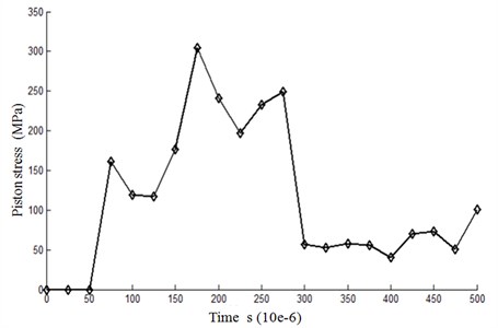
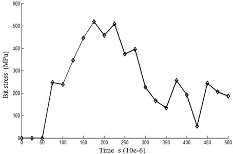
Fig. 10 shows the equivalent stress curve during the collision process. It can be seen that the stress of the drill bit reaches a maximum value of 519 MPa at 175 μs, and the bit's stress reduces to 227 MPa at 300 μs. The variation trend of equivalent stress on each variable section of the bit is the same, but there are also minor differences in tress value.
To sum up, the safety factor of the piston is 2.8, and that of the drill bit is 2.35, which can meet actual security requirements. In addition, by comparing Fig. 9 and Fig. 10, the stress of the drill bit is greater than that of the piston at the same point in time, so the strength of the drill bit material should be higher when selecting the materials.
Fig. 10Equivalent stress curve of the drill bit in plane 2
4.3. Analysis of final impact velocity
When the piston mass is constant, the higher the compressed gas enters the hammer, the faster the piston impacts the drill bit and the greater the energy transmitted to the rock. However, at this time, the amplitude of the stress wave will increase, which may cause the maximum stress on the piston or drill bit to exceed the fatigue strength of the material, resulting in deformation or fracture of the piston or drill bit, and reduce the service life of piston or drill bit. Therefore, it is necessary to limit the maximum impact final velocity of the piston. The maximum stresses of piston and bit at different final impacting speeds are analyzed and shown in Table 2. The maximum stress of the piston and bit increase with the impacting velocity. When the final impact velocity of the piston is larger than 10.5 m/s, the safety factor of both piston and bit are lower than 1.5. Thus, the Final impact velocity should be less than 10.5 m/s.
Table 2Material parameters of piston and drill bit
Final velocity (m/s) | The maximum stress of piston (MPa) | The maximum stress of bit (MPa) | Safety factor of piston | Safety factor of bit |
6.5 | 304 | 519 | 2.80 | 2.35 |
7.5 | 374 | 639 | 2.30 | 1.90 |
8.5 | 428 | 729 | 1.99 | 1.67 |
9.5 | 445 | 736 | 1.91 | 1.65 |
10.5 | 480 | 819 | 1.78 | 1.50 |
11.5 | 567 | 943 | 1.49 | 1.29 |
12.5 | 607 | 1031 | 1.4 | 1.18 |
13.5 | 658 | 1138 | 1.29 | 1.07 |
14.5 | 728 | 1242 | 1.17 | 0.98 |
5. Experiment validation of structural design
Fig. 11 describes the schematic of a test device, which consists of a data acquisition system, an air compressor, a mainframe, a novel hammer, and rocks. This test device can set the inclination angle from 0° to 90° by chains. Through motor and chain, the hammer can be adjusted under certain angular velocity and compression force. The air supplied by a compressor is infused through the motor and enters the hammer via a short drill rod joint. Through a series of experiments, we verify the rationality of the proposed mechanical design and achieve the working behaviors.
Fig. 11Schematic view of the multifunctional pneumatic hammer test device
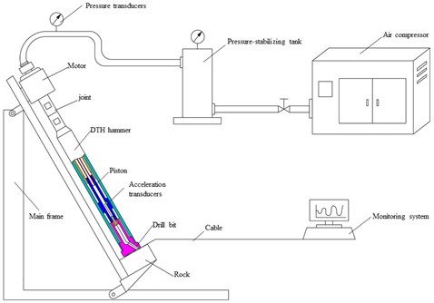
Fig. 12Impact piston displacement curve
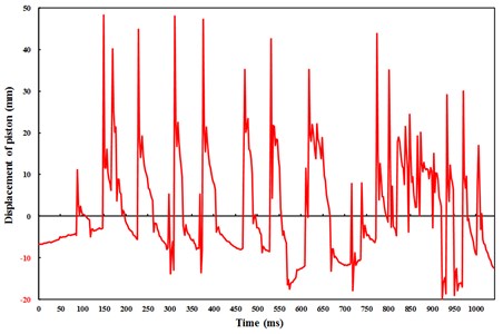
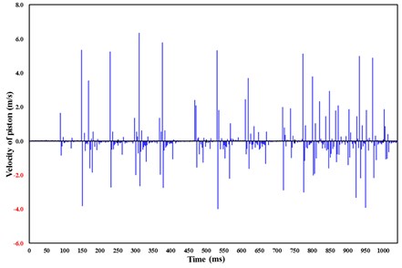
Fig. 13Impact piston velocity curve
To accurately establish the motion law of the piston, an acceleration transducer is embedded in the low part of the piston. This transducer can record the motion of the piston under varying conditions of different working pressures, such as velocity, acceleration, displacement, and impact frequency. All of the experimental data captured by high-speed data acquisition are used to precisely record and analyze the operational status of the hammer [23].
Under operating pressure, the novel hammer can execute regular working cycles, and the drill bit's self-rotating motion is achieved during the return stroke process. The acceleration transducer can measure the movement of the piston and record some data. Based on the displacement curve and velocity curve (shown in Fig. 12 and 13), we can analyze the motion laws of the piston and determine operation parameters such as final impact velocity and frequency.
6. Conclusions
This paper designs a novel DTH Hammer with self-rotation bit based on the combination of DTH hammer and pneumatic rock drill. This combination takes advantage of them and conquers their disadvantages.
1) This novel pneumatic hammer fully utilizes the energy of return stroke to realize the self-rotation of the drill bit. It is pneumatically operated with compressed air supplying the energy for percussion, and it can break rocks efficiently by percussive rotary drilling.
2) The hammer can rotate with high-pressure gas input while the drill pipe is static without a drilling rig. Meanwhile, the quality of the borehole and stiffness of the drill pipe is improved, and the efficiency of breaking rocks increases simultaneously. It makes a great significance to geological explorations and engineering constructions.
3) Ansys was used to analyze the impact dynamics of the piston and bit and check the strength. We can obtain the maximum stress of piston and bit in the breaking process through analyzing the results and energy transfer. These have referenced value to the choice of the material. In addition, the reasonable impact velocity of the piston was proposed by analyzing the maximum stress of the piston and bit at different final impact velocities. The choice of gas pressure in the actual work is of great significance.
4) A validation experiment of the novel hammer is executed on the hammer test device, and the design principle and theory indicate feasibility.
References
-
X. Song, O. M. Aamo, P.-A. Kane, and E. Detournay, “Influence of weight-on-bit on percussive drilling performance,” Rock Mechanics and Rock Engineering, Vol. 54, No. 7, pp. 3491–3505, Jul. 2021, https://doi.org/10.1007/s00603-020-02232-x
-
Bo K., Yin K., and Peng J. M., “Reverse circulation DTH hammer drilling technique,” Global Geology, Vol. 14, No. 5, pp. 259–264, 2011.
-
Y. Li, J. Peng, P. Zhang, and C. Huang, “Hard rock fragmentation in percussion drilling considering confining pressure: insights from an experimental study,” International Journal of Rock Mechanics and Mining Sciences, Vol. 148, p. 104961, Dec. 2021, https://doi.org/10.1016/j.ijrmms.2021.104961
-
T. Saksala, “Numerical study of the influence of hydrostatic and confining pressure on percussive drilling of hard rock,” Computers and Geotechnics, Vol. 76, pp. 120–128, Jun. 2016, https://doi.org/10.1016/j.compgeo.2016.02.021
-
B. Lundberg and M. Okrouhlik, “Efficiency of a percussive rock drilling process with consideration of wave energy radiation into the rock,” International Journal of Impact Engineering, Vol. 32, No. 10, pp. 1573–1583, Oct. 2006, https://doi.org/10.1016/j.ijimpeng.2005.02.001
-
Michael S. Bruno, “Fundamental Research on Percussion Drilling: Improved rock mechanics analysis, advanced simulation technology, and full-scale laboratory investigations,” Office of Scientific and Technical Information (OSTI), Technical Report, Dec. 2005.
-
C. Song, J. Chung, J.-S. Cho, and Y.-J. Nam, “Optimal design parameters of a percussive drilling system for efficiency improvement,” Advances in Materials Science and Engineering, Vol. 2018, pp. 1–13, 2018, https://doi.org/10.1155/2018/2346598
-
L. E. Chiang and E. B. Stamm, “Design optimization of valveless DTH pneumatic hammers by a weighted pseudo-gradient search method,” Journal of Mechanical Design, Vol. 120, No. 4, pp. 687–694, Dec. 1998, https://doi.org/10.1115/1.2829332
-
W. Liu, X. Zhu, and B. Li, “The rock breaking mechanism analysis of rotary percussive cutting by single PDC cutter,” Arabian Journal of Geosciences, Vol. 11, No. 9, May 2018, https://doi.org/10.1007/s12517-018-3530-6
-
D.-J. Kim, J.-Y. Oh, J.-W. Cho, J. Kim, J. Chung, and C. Song, “Design study of impact performance of a DTH hammer using PQRSM and numerical simulation,” Journal of Mechanical Science and Technology, Vol. 33, No. 11, pp. 5589–5602, Nov. 2019, https://doi.org/10.1007/s12206-019-1052-0
-
D.-J. Kim et al., “Prediction model of drilling performance for percussive rock drilling tool,” Advances in Civil Engineering, Vol. 2020, pp. 1–13, Dec. 2020, https://doi.org/10.1155/2020/8865684
-
Meng Q. K., Wang X. D., and Yu X. S., “KQC series of air hammers for gas drilling in oil field,” (in Chinese), Oil Field Equipment, Vol. 36, No. 11, pp. 54–57, 2007.
-
C. Bu, X. Li, L. Sun, and B. Xia, “Arithmetic solution for the axial vibration of drill string coupling with a down-the-hole hammer in rock drilling,” Journal of Vibration and Control, Vol. 22, No. 13, pp. 3090–3101, Jul. 2016, https://doi.org/10.1177/1077546314560041
-
C. Bu, Y. Qu, Z. Cheng, and B. Liu, “Numerical simulation of impact on pneumatic DTH hammer percussive drilling,” Journal of Earth Science, Vol. 20, No. 5, pp. 868–878, Oct. 2009, https://doi.org/10.1007/s12583-009-0073-5
-
A. Depouhon, V. Denoël, and E. Detournay, “Numerical simulation of percussive drilling,” International Journal for Numerical and Analytical Methods in Geomechanics, Vol. 39, No. 8, pp. 889–912, Jun. 2015, https://doi.org/10.1002/nag.2344
-
Z. Zhao, Y. Meng, Y. Li, X. Shi, and C. Xiang, “Effects of working angle on pneumatic down-the-hole hammer drilling,” Rock Mechanics and Rock Engineering, Vol. 48, No. 5, pp. 2141–2155, Sep. 2015, https://doi.org/10.1007/s00603-014-0667-9
-
H. Song, H. Shi, G. Li, Z. Chen, and X. Li, “Numerical simulation of the energy transfer efficiency and rock damage in axial-torsional coupled percussive drilling,” Journal of Petroleum Science and Engineering, Vol. 196, p. 107675, Jan. 2021, https://doi.org/10.1016/j.petrol.2020.107675
-
K. Wu and Z. Ye, “The numerical research on rock breaking and rising mechanism of rotary-percussive drilling,” Arabian Journal for Science and Engineering, Vol. 44, No. 12, pp. 10561–10580, Dec. 2019, https://doi.org/10.1007/s13369-019-04170-5
-
H. X. Jiang et al., “Experimental and numerical investigation of hard rock breakage by indenter impact,” Shock and Vibration, 2020, https://doi.org/10.1155/2020/274783
-
H. Song et al., “The percussive process and energy transfer efficiency of percussive drilling with consideration of rock damage,” International Journal of Rock Mechanics and Mining Sciences, Vol. 119, pp. 1–12, Jul. 2019, https://doi.org/10.1016/j.ijrmms.2019.04.012
-
J. O. Hallquist, “LS-DYNA theory manual, livermore software technology corporation,” USA, 2019.
-
Y. Hu, “Study on DTH with self-propelled round bit and its simulation analysis,” Ph.D. Thesis, Jilin University, 2007.
-
K. Bo, S. Sun, Y. Hu, and M. Wang, “Design optimization and performance analysis of the pneumatic dth hammer with self-propelled round bit,” Shock and Vibration, Vol. 2021, pp. 1–13, Jul. 2021, https://doi.org/10.1155/2021/6653390
Cited by
About this article

This work was financially supported by the National Key Research and Development Program of China (Grant No. 2018YFC1505303) and Natural Science Foundation of Jilin Province, China (Grant No. 20210101102JC).
