Abstract
Electric power steering (EPS) system is becoming the primary source of Electric Vehicle (EV) noise due to absence of classic power train. The rattle noise produced by EPS, which is easily discernible when driving. Since the conventional subjective evaluation approach makes it difficult to identify the source, it is required to establish an objective way to solve such an issue. In this paper, the principle of multiple coherence method is first addressed analytically, and then is employed to analyze the vibration signal acquisition from EPS different points, meanwhile, combine with in-car sound signal, to accurately identify the specific location.
1. Introduction
In recent years, with the development of electric vehicle, the background noise during driving has been significantly decreased, resulting in squeak and rattle that are easy to be perceived [1]. As the development of EVs and even the autonomous driving technology advances, is it demanding to improve the performance of EPS [2], and hence P-EPS will be widely used, the identification and location of such unwanted sound source becomes more complicated [3].
From present studies on the rattle noise of the steering system, it can be seen that de Oliveira [1] analyzed the frequency characteristics of the noise of Moan and Hiss. For steering gear rattle noise, Taenaka [4] proposed a neural network method to predict the rattle noise of steering gear by collecting the acceleration signal of relevant position. For the objective evaluation of the undesired noise of the steering system, Sharma et al. [5] analyzed the collected vibration signals of the steering gear under different roads, and combined the FFT analysis method and different filter analysis methods to further identify the specific location of rattle.
By reviewing the previous research findings, it is found that the majority of study on the such disturbing noises of the steering system are based on the laboratory bench, and also there is a lack of systematic explanation of mechanical principles of the phenomenon, as well as limited repeat-ability in lab due to the steering system connection structure. So this article first attempt to take the advantage of multiple coherence method to investigate the steering system rattle in the state of the whole vehicle. González et al. [7] studied the time domain multiple coherence method for the analysis of the transmission path. Wądołowski et al. [8] used this method to separate the effective signals in the acquisition signal, in order to obtain the required and useful characteristic information.
2. Mathematical principle of multiple coherence method
For the rattle noise issue of the complex structure of the steering system, the vibration model should be in the form of multiple input and single output, and there is a certain correlation between each input [9], the model is shown in Fig. 1.
Fig. 1Multi-input single-output system model
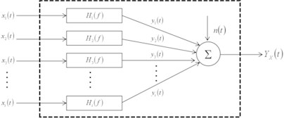
In general, multiple coherence method is used for analysis of this type of model [10], so that the causal relationship between all the inputs and outputs can be well solved, allowing the rattling noise in the vibration signal (non-stationary vibration signal) to be distinguished [11]. For this type of linear system, the auto power spectrum of output is , and the cross power spectrum between the th input and output can be expressed as:
where, is the number of degrees of freedom input; and are frequency response functions between input and and output , respectively. When there is no correlation between input and other inputs , and the average number of power spectrum calculations is sufficient, there is , then the above expression can be written as:
At this time, the ordinary coherence function is equal to the ratio of the output caused by the input to the total output obtained from the physical test. According to Fig. 4, the multiple coherence function between the output and inputs , is defined as the ratio of the ideal linear output spectrum to the total output spectrum , then:
where, is the output spectrum of external interfering noise, then there is:
The symbol indicates generation due to the input part . It can be seen from Eqs. (1) and (2) that the general form is:
Owing to and , and all terms are non-negative, and therefore, exists for all frequencies:
According to Eq. (7), the product of the multiple coherence function and the output spectrum is expressed as:
The product is the multiple coherence output power spectrum, which represents the part of the output spectrum contributed by all testing inputs , , the output generated by these testing inputs.
Next, the analysis of the testing results is based on the basis of multiple coherence theory. In this paper, the input signal are acquisition from vibration signals via acceleration at various relevant positions of the steering system [14], and the output signal are collected by microphone at the left ear of the driver in the car.
3. Rattle noise experimental testing in vehicle
The rattle noise of the steering system is usually perceived when the vehicle is driving on rough roads at a speed of 10 km/h-30 km/h [6], a continuous impacting sound can be heard very clearly in the vehicle through subjective evaluation. The phenomenon and the working conditions of this annoying noise are shown in Fig. 2. It is referred to as “rattle” in the previous section.
Fig. 2Flowchart of condition of steering rattle noise

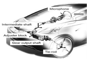
And then, a microphone is placed at the driver’s left ear position in the vehicle, and a tri-axis accelerometer is arranged at relevant positions of the steering system, such as intermediate shaft, backlash adjuster, gear output shaft and tie rod joint [5, 15], as shown in Fig. 3. Then the vehicle driving on a rough road at a constant speed of 15 km/h to measure sound and acceleration signals at relevant positions.
Fig. 3Acceleration and microphone layout locations
Eventually, according to the transfer path of the undesired sound of the steering system [16], to locate the specific location of the undesired noise and analyze the collected vibration and sound data, to determine its frequency range, so as to achieve the purpose of solving the issue.
4. Result and analysis of rattle noise
Based on the principle of multiple coherence analysis, the collected signals are analyzed [7]. Fast Fourier Transform is performed aiming to the sound signal to observe its spectrum characteristics in the frequency domain, as shown in the Fig. 4.
Fig. 4Analysis result of rattle with FFT
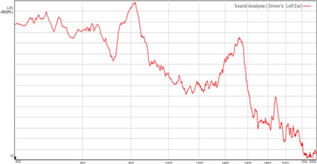
Through the spectrum analysis, it can be seen that there are obvious peaks near 800 Hz and 1500 Hz, but it can not be determined from the above figure whether the rattle is caused by both two different frequencies, so further analysis of the vibration data of the relevant location is required. By analyzing the vibration signals acquisition from different positions of the steering system, in Fig. 5 it can be found that the acceleration at the position of the backlash adjuster has an obvious peak near 1500 Hz.
Fig. 5Multiple coherence result of backlash adjuster location
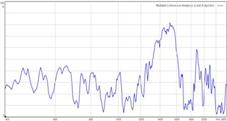
After superposition and comparison of the multiple coherence diagram of the vibration signal collected at the backlash adjuster and the spectrum analysis of the sound signal, as shown in Fig. 6 left, the relationship between them can be understood more clearly. It is not difficult to find that the coherence analysis spectrum is consistent with the shape of the spectrum analysis diagram of the sound at 1200 Hz and above, and it is also an apparent peak near appearing at 1500 Hz.
Fig. 6Comparison of analysis results between backlash adjuster and rattle signal
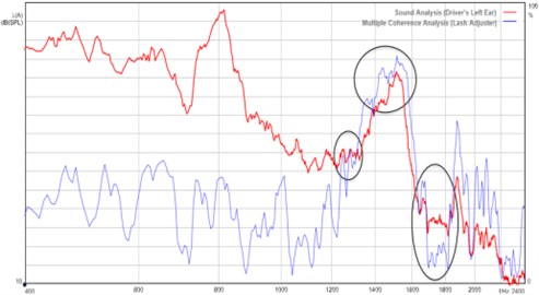
It can be inferred that the vibration at the backlash adjuster contributes greatly to the undesired noise heard inside vehicle, but needs to be excluded in order to further ascertain the undesired noise source [13], so the contribution of other relevant positions needs to be further analyzed.
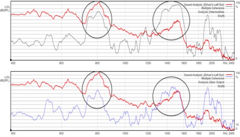
The vibration input from which position contributes the most to the rattling is assessed based on the similarity shape features of the spectrum signal. The multiple coherent spectrum of vibration input at the site of the intermediate shaft and gear output shaft is compared with the spectrum of sound signal gathered in the vehicle, as illustrated in Fig. 7.
According to the comparative results, the signal coherence in the low frequency range is weak, but the coherence level and peak shape in the high frequency range of the gear output end position are generally comparable. As a result, the rattling noise is further restricted to the combination position of the gear and the rack. The backlash adjuster's role is to regulate the structural space between the gear and the rack [12]. As a result, the peak frequency of the signal at the lash adjuster is closest to the shape of the sound signal. When the internal structure of the position is considered, it is clear that the rattle is mostly caused by the rack and pinion. The clearance fit is too excessive, resulting in increased vibration input from the road surface, which causes collisions, and thus resulting in rattle noise.
Fig. 7Comparison of analysis results between backlash adjuster and rattle noise
5. Conclusions
Based on the above analysis, it can be seen that the main source of rattling noise in the steering system is mainly due to the excessive gap between the gear rack and the pinion. Since the generation of such noise is easily induced under particular excitation circumstances and produces an unstable signal in time domain, subjective evaluation makes it difficult to pinpoint the precise location of its generation. In this paper, the method of multiple coherence in signal processing is used to analyze the different vibration input positions and the linear relationship with the sound signal collected in the vehicle in the frequency domain, so as to determine the rattle source.
References
-
de Oliveira and Paulo Afonso Coppi Aquino, “Power steering noise characterization and evaluation,” in SAE Brasil Noise and Vibration Conference, Mar. 2008, https://doi.org/10.4271/2008-36-0550
-
Ando Koji, Murohashi Atsuo, Fujikake Mitsuhiko, and Horikawa Takeshi, “Development of electric power steering evaluation system,” KYB Technical Review, Vol. 56, pp. 37–42, 2018.
-
S. Nishimura and S. Abe, “Development of rattle noise analysis technology for column type electric power steering systems,” JTEKT Engineering Journal, Vol. 1009E, pp. 66–71, 2012.
-
M. Taenaka, “Establishment of evaluation method for rattle noise of steering gear for column type EPS system,” JTEKT Engineering Journal, Vol. 1008E, pp. 55–58, 2011.
-
U. Sharma, S. T. Wilson, S. Lalasure, and K. Rajakumar, “Quantitative evaluation of steering system rattle noise,” in International Conference on Advances in Design, Materials, Manufacturing and Surface Engineering for Mobility, Jul. 2017, https://doi.org/10.4271/2017-28-1952
-
R. Kamath, “steering system noise evaluation,” in 9th International Styrian Noise, Vibration and Harshness Congress: The European Automotive Noise Conference, Jun. 2016, https://doi.org/10.4271/2016-01-1832
-
A. Gómez González, J. Rodríguez, X. Sagartzazu, A. Schuhmacher, and I. Isasa, “Multiple coherence method in time domain for the analysis of the transmission paths of noise and vibrations with non stationary signals,” in Proceedings of ISMA 2010 – International Conference on Noise and Vibration Engineering, including USD 2010, pp. 3927–3941, 2010.
-
M. Wądołowski, J. Pankiewicz, and D. Markuszewski, “Application for analysis of the multiple coherence function in diagnostic signal separation processes,” Vibrations in Physical Systems, Vol. 31, No. 3, p. 20203, 2020, https://doi.org/10.21008/j.0860-6897.2020.3.24
-
G. W. Lin and Y. Y. Liu, “Application of multiple coherence analysis method in vehicle vibration research,” Chinese Journal of Applied Mechanics, Vol. 2, No. 1, pp. 141–146, 1985.
-
C. Peng, H. Yan, D. Ren, R. C. Kang, and Z. G. Chu, “Road noise decomposition based on multiple coherence method,” Noise and Vibration Control, Vol. 4, No. 3, pp. 169–174, 2021.
-
Y. Yang and Z. G. Chu, “Multiple coherence decomposition method for road noise of a car,” Journal of Vibration and Shock, Vol. 34, No. 19, pp. 31–36, 2015, https://doi.org/10.13465/j.cnki.jvs.2015.19.005
-
Y. Kozaki, G. Hirose, S. Sekiya, and Y. Miyaura, “Electric power steering,” Motion and Control, Vol. 6, pp. 9–15, 1999.
-
J. N. Da Silva and J. R. A. Zanini, “Design of experiments application (DOE) to prevent mechanical noise in power rack and amp; pinion steering systems,” in 2004 SAE Brasil Congress and Exhibit, Nov. 2004, https://doi.org/10.4271/2004-01-3377
-
L. Graeff, Y. Kandinov, and S. Redfearn, “NVH test rig for integrating the steering system,” ATZ worldwide, Vol. 120, No. 1, pp. 50–55, Jan. 2018, https://doi.org/10.1007/s38311-017-0146-5
-
M. Kanatsu, “Technologies of NV measurement and analysis for steering system,” Motion and Control, Vol. 31, pp. 8–23, 2020.
-
H. Ishii, H. Uemura, Z. Zhang, and H. Ikeuchi, “Identification of noise source in electric power steering system using wavelet transform,” in SAE 2007 Noise and Vibration Conference and Exhibition, May 2007, https://doi.org/10.4271/2007-01-2272
About this article

