Abstract
Mass and center of mass are important mass characteristic parameters, and these parameters have a direct impact on the space motion attitude, motion trajectory, and flight stability of the rotor UAV. In this paper, the multi-point weighing method is used to measure the mass and three-dimensional center of mass of the rotary-wing UAV, the measurement principle is deeply analyzed and the system error is deeply studied. It can provide theoretical guidance for the development of test equipment for the mass and three-dimensional center of mass of the rotor UAV.
Highlights
- The mass and three-dimensional center of mass of the rotary-wing UAV were measured by multi-point weighing method.
- The calculation formulas of mass, three-dimensional centroid and system synthesis error are deduced.
- The measurement principle is deeply analyzed and the systematic error is deeply studied.
1. Introduction
As a product of the development of modern science and technology, UAVs are playing an increasingly important role in the military and civilian fields [1]. UAVs mainly feed back important control information such as flight attitude and heading trajectory to operators through ground stations. An important parameter that affects this information is the quality characteristic parameter [2]. The mass characteristic parameters include four parameters: mass, the center of mass, a moment of inertia, and inertia product [3]. The center of mass has a direct impact on the space motion attitude, motion trajectory, and flight stability of small UAVs. The force of small UAVs is relatively complex during the flight process. Accurately measuring the mass and center of mass of the UAV can accurately analyze the force, avoid the UAV from deviating from the flight trajectory, and improve the flight performance. Due to the higher requirements of users on the performance indicators of UAVs, the size and structure of UAVs are getting smaller and smaller, but the functions are increasing [4]. As a result, the internal structure of the UAV is more complex, various components are distributed in it, and the mass distribution is uneven. Therefore, the accuracy of the mass center parameter calculated by the classical theoretical model cannot meet the requirements of UAV technology itself, and cannot be used as its The control parameters of the flight attitude are used, therefore, it is necessary to determine the mass and center of mass of the UAV by an experimental method [5]. However, the measurement equipment for the quality characteristics of UAVs recorded in the literature is mainly designed for fixed-wing UAVs. The equipment covers a large area and can only measure specific types of UAVs. For example, Wang Guogang et al. used the projection method to measure the position of the center of mass of the fixed-wing UAV, which reduced the test cost and improved the test accuracy [6]. Chen Ping et al. used the four-point weighing method to measure the center of mass of a large fixed-wing UAV, which improved the measurement efficiency [7]. Gopinath used the inverted torsion pendulum method and the multi-point weighing method to measure the mass characteristics of the spacecraft. Although the accuracy of the measurement system is improved [8] when testing the center of mass of the spacecraft, only the two-dimensional center of mass can be measured, usually, the three-dimensional centroid of the measured object needs to be detected, so this research is not perfect. Although domestic and foreign scholars have done some research on the quality characteristics of fixed-wing UAVs, there are still some problems that need to be further improved. At the same time, the test equipment for measuring the mass characteristics of the rotary-wing UAV has yet to be developed. Therefore, the test principle of the mass center of the rotary-wing UAV is studied in this paper, and the error analysis is carried out. It provides a theoretical basis for the actual development of test equipment for measuring the quality characteristics of rotary-wing UAVs.
2. Principle of quality and centroid testing
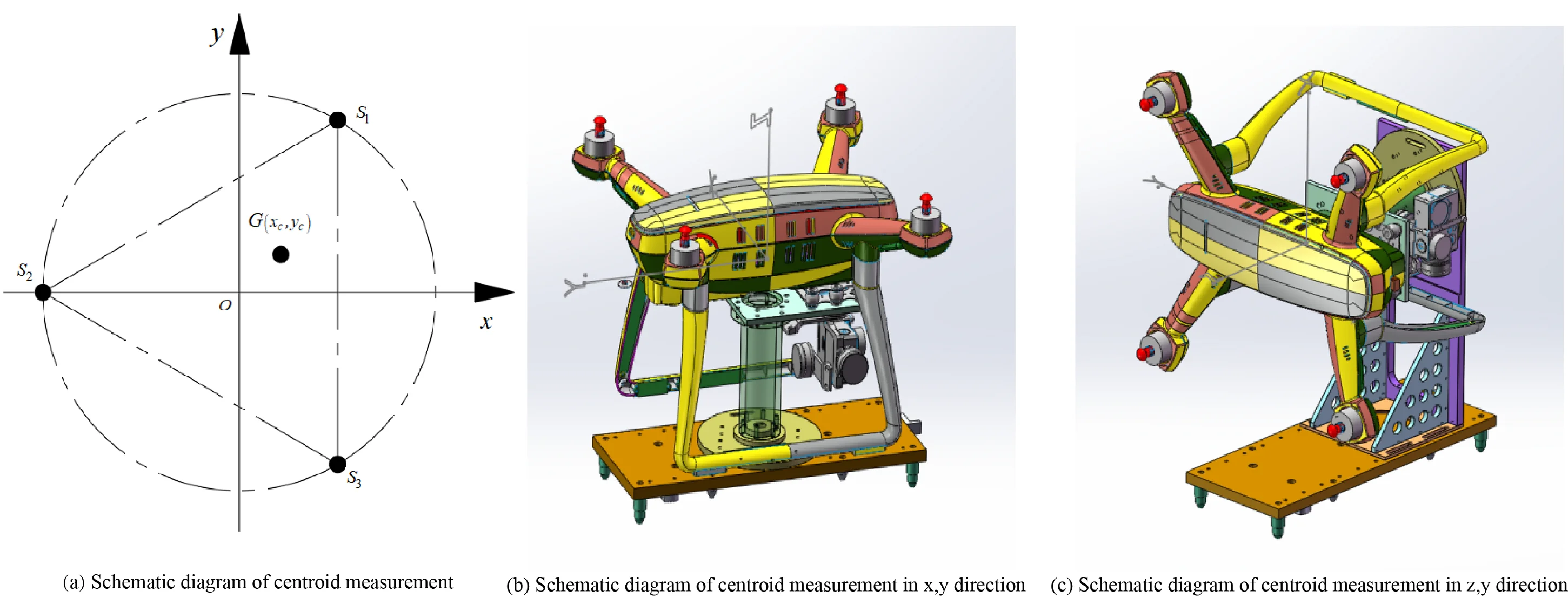
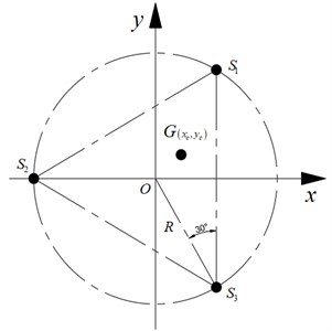
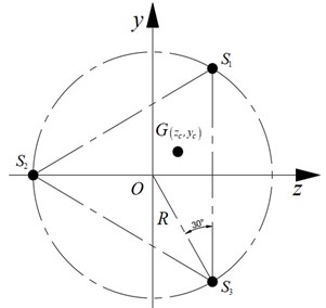
The measurement methods of the center of mass mainly include the geometric drawing method, zero position method, suspension method, compound pendulum method, mass response method, trimming method, multi-point weighing method, etc. [9]. The multi-point weighing method has a simple structure, and the sensor can be replaced according to the actual situation to adjust the measurement range and is not affected by the shape and size of the sample. By selecting the sensor reasonably and arranging the position of the sensor reasonably, the measurement accuracy can be up to 0.01 mm [10]. As shown in Fig. 1, the mass and centroid test adopts the test principle of the three-point weighing method. The three load cells , , and are respectively located on the circle with the origin of the coordinate system as the center and the radius of R, and the connection lines of the three sensors form an equilateral triangle.
Fig. 1Schematic diagram of the measurement of the centroid of the x, y-axis
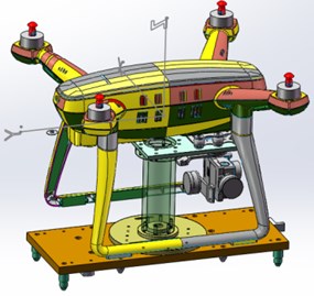
Place the drone horizontally on the measuring table, as shown in Fig. 2(a), the data measured by sensors , , and are, , , respectively. Eq. (1) is obtained according to the static equilibrium equation;
Take the moments on the -axis and -axis respectively to get the balance equation:
The expressions of and are sorted as:
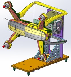
After the centroid of the drone in the and -axis directions is measured, to measure the centroid of the -axis of the drone, it is necessary to rotate the drone around the -axis by 90°, as shown in Fig. 2(b).
Fig. 2Schematic diagram of 3D centroid measurement
a)
b)
The principle of measuring the -axis centroid is shown in Fig. 3.
Fig. 3Schematic diagram of z, y-axis centroid measurement
According to the static balance equation, the center of mass of the -axis can be obtained:
The mass and three-dimensional center of mass of the UAV are calculated by Eqs. (1), (4), (5), and (6).
3. Quality and centroid test error analysis
3.1. Quality error analysis
The mass error is mainly due to the random error brought by the three load cells. If the error of each sensor is ( 1, 2, 3), the total error of the UAV mass measurement can be obtained according to Eq. (7):
where is the correlation coefficient between any two load cells, because, in the actual measurement process, each sensor is independent of each other, so .
The range of the load cell selected for this test is 0-5 kg, and the accuracy is 0.01 %. Usually, the mass measurement error is 0.01 % of the full scale of the sensor, and the error of each sensor can be expressed as Eq. (8):
Therefore, from Eq. (7), the maximum error of the mass of the UAV is known as .
3.2. Centroid measurement error
The measurement error of the centroid mainly depends on the measurement error of the load cell and the positioning error of the sensor. The positioning error is mainly related to the installation position of the sensor and the levelness of the test bench.
3.2.1. Centroid error caused by mass measurement error
The centroid calculation error caused by the mass measurement error can be expressed by Eq. (9):
Take the partial derivative of Eq. (4) for , , and and bring it into Eq. (9) and combine Eq. (8) to obtain Eq. (10):
Take the partial derivative of Eq. (5) with respect to , , and and bring it into Eq. (9) and combine Eq. (8) to obtain Eq. (11):
The same can be obtained:
3.2.2. The centroid error caused by the positioning error
The centroid error caused by the positioning error of the load cell is a systematic error, including positional and flatness errors. The position of the sensor positioning hole is 0.0 3mm, the levelness of the test bench is better than 0.002 mm, and the comprehensive error 0.032 mm can be obtained. If the comprehensive errors of the three sensors are , , to ensure that the error is minimized, , can be taken, then the centroid error can be expressed as Eq. (13) and Eq. (14):
3.2.3. Centroid comprehensive test error
The components of the centroid in the , , and directions can be obtained by taking Eqs. (10) to (14) into Eq. (15), and taking the calculation result of Eq. (15) into Eq. (16) to obtain the error of the centroid:
4. Experimental data analysis
4.1. Mass uncertainty analysis
A standard weight with a specification of 5 kg was selected for the experiment, and the experimental results are shown in Table 1. The relative error of the measurement results is analyzed using the Bessel formula. The basic Bessel formula is as follows:
where represents the residual of the -th measurement data.
Table 1Measurement results of standard weights
1 | 2 | 3 | 4 | 5 | 6 | 7 | 8 | 9 | 10 | |
Measured value (g) | 5001.8 | 5001.6 | 5001.5 | 5001.7 | 5001.9 | 5001.6 | 5001.8 | 5001.6 | 5001.4 | 5001.7 |
Using Eq. (17), the standard uncertainty of mass measurement is 1.7563 g, the expanded uncertainty is 5.2689 g, and the relative uncertainty is 0.105 %, which meets the accuracy requirements.
4.2. Centroid uncertainty analysis
A standard sample with a known three-dimensional centroid was selected for measurement, and the measurement results are shown in Table 2. The three-dimensional centroids of the standard samples are 0 mm, 0 mm and 40 mm respectively.
Using the average value of multiple measurement results as the measurement value, the errors of the three-dimensional centroid are obtained as 0.152 mm, 0.148 mm and 0.17 mm respectively. The errors are all less than 0.2 mm, which meets the accuracy requirements.
Table 2Measurement results of standard samples
Experiment number | (mm) | (mm) | (mm) |
1 | 0.15 | 0.13 | 40.22 |
2 | 0.13 | 0.12 | 40.16 |
3 | 0.17 | 0.15 | 40.18 |
4 | 0.16 | 0.16 | 40.15 |
5 | 0.15 | 0.18 | 40.14 |
Average value | 0.152 | 0.148 | 40.17 |
5. Conclusions
This paper uses the three-point weighing method to test the mass and three-dimensional center of mass of the rotary-wing UAV, analyzes the test principle, conducts an in-depth study of the system error, and deduces the expression of the comprehensive error. The calculation formulas for calculating the mass and three-dimensional center of mass of the rotor UAV are obtained, which can provide theoretical guidance for the development of test equipment for the mass and three-dimensional center of mass of the rotor UAV.
References
-
M. Idrissi, M. Salami, and F. Annaz, “A review of quadrotor unmanned aerial vehicles: applications, architectural design and control algorithms,” Journal of Intelligent and Robotic Systems, Vol. 104, No. 2, pp. 1–33, Feb. 2022, https://doi.org/10.1007/s10846-021-01527-7
-
L. Teng, H. Yang, and Z. Jin, “Novel measurement method for determining mass characteristics of pico-satellites,” Applied Sciences, Vol. 8, No. 1, p. 104, Jan. 2018, https://doi.org/10.3390/app8010104
-
M. Pisani et al., “A device for measuring the Moment of Inertia for aerospace applications,” in 2019 IEEE 5th International Workshop on Metrology for AeroSpace (MetroAeroSpace), pp. 687–691, Jun. 2019, https://doi.org/10.1109/metroaerospace.2019.8869668
-
Kim J. et al., “Unmanned aerial vehicles in agriculture: a review of perspective of platform, control, and applications,” IEEE Access, 2019.
-
Jin-Kang Ma and Yan-Rong Tong, “Design and development of intelligent torsion pendulum method for rotational inertia measurement experiment,” in 9th International Conference on Information Technology in Medicine and Education, pp. 442–446, 2018.
-
Wang Gangguo et al., “A method for measuring gravity center and inertia moments of UAV,” Aero Weaponry, Vol. 5, pp. 7–11, 2013.
-
Chen Ping, Deng Gaofu, and Wu Haiying, “Research on integrated measuring device of mass property parameters for aircraft model,” Mechanical Science and Technology for Aerospace Engineering, Vol. 34, No. 12, pp. 1891–1895, 2015.
-
Gopinath K. et al., “Product design aspects for design of accurate mass properties measurement system for aerospace vehicles,” Applied Mechanics and Materials, Vol. 110, pp. 4712–4718, 2012.
-
X. Zhao, J. Kang, T. Lei, Y. Wang, and Z. Cao, “Vehicle centroid measurement system based on forward tilt method error analysis,” IOP Conference Series: Materials Science and Engineering, Vol. 452, No. 4, p. 042189, Dec. 2018, https://doi.org/10.1088/1757-899x/452/4/042189
-
Zhang Zhang et al., “Method for measuring the centroid of large aerospace samples,” Metrology and Measurement Technology, Vol. 31, No. 3, pp. 56–57, 2011.
About this article

The authors would like to thank the national natural science foundation of China U1937201, Science and technology development plan project of Jilin province No. 20200301040RQ and 20210201057GX, Science and technology research project of Jilin Provincial Department of Education No. JJKH20220734KJ.
