Abstract
The shortest distance from the deep foundation pit envelope of the project to the subway station building is only 7.7 meters, and the deepest excavation depth of the foundation pit is about 24 meters. The surrounding environment of the foundation pit is complex, involving many buildings, the construction is difficult, and there is a great risk of construction safety. The effective control of the structural deformation of the existing subway station is the key to selecting the underground enclosure structure and construction process of the surrounding post-construction projects. Combined with the actual situation of the project, the three-dimensional numerical analysis method is used to analyze the impact of the construction of the foundation pit of the building on its adjacent structures in detail, and the relevant treatment measures are proposed. The research shows that the unloading effect caused by the large-scale excavation causes the soil outside the pit to move towards the inside of the pit. Under the influence of the soil deformation transfer effect, the Beiguan Station of the R1 line subway produces certain rebound, settlement and horizontal displacement, but the values of each deformation index are within the deformation control standard, the numerical analysis considering the influence of small soil strain can better reflect the influence of foundation pit excavation on the displacement, deformation and internal force of the existing structure. It can better match the actual engineering experience.
Highlights
- The shortest distance from the deep foundation pit envelope of the project to the subway station building is only 7.7 meters, and the deepest excavation depth of the foundation pit is about 24 meters.
- This paper mainly studies the influence of the foundation pit excavation on the subway structure of Beiguan Station of the R1 line on the south side: the calculation and verification of the envelope structure of the foundation pit project is limited.
- PLAXIS geotechnical finite element software is used to analyze the research content.
1. Introduction
During the excavation of the foundation pit, due to factors such as excavation disturbance, stratum loss and consolidation settlement, the stratum will move and deform, resulting in the movement and deformation of the existing subway station structure attached to the stratum, and then Cause the change of the force of the station structure, and the important structures associated with the main structure of the station will also move and deform. Therefore, the effective control of the structural deformation of the existing subway station is the key to select the underground envelope structure and construction process of the surrounding post-construction projects.
The construction environment around the station is complex, with dense buildings and structures, and the natural geological environment is changeable. At this stage, people's research on engineering environmental problems is mostly based on the stage of experience summarization. Theoretical-based research, such as literature [1-4], is mainly based on the two-stage analysis method to conduct in-depth research on the deformation of adjacent subway tunnels caused by foundation pit excavation, experimental-based research, such as literature [5-7], mainly The influence law of foundation pit excavation on the deformation and internal force of the subterranean and lateral tunnels is studied through the centrifuge model test and the constant gravity full-scale or reduced-scale model test. The influence of foundation pit excavation and various control and protection measures on the adjacent subway tunnels, based on the research on the analysis and summary of actual measurements, such as literature [11-13], according to the monitoring data results of the comprehensive action of multiple factors on the project site, the disturbance of foundation pit excavation is discussed. The regular characteristics that cause the deformation of the tunnel are summarized, and the guiding significance of the project is summarized. However, there are not many achievements in the digitization and modeling of basic theory, and there are few researches based on super-deep and large foundation pits. For example, the impact of building foundation pit construction on its adjacent structures is sometimes determined by empirical methods, but the results are often difficult to meet the requirements for use. Especially when other engineering projects are built near the existing subway station, if the potential dangers of the surrounding projects to the existing subway station cannot be properly assessed, the economic loss and social impact will be difficult to estimate. The impact of deep and large foundation pits on the safety of surrounding buildings is of great significance.
2. Project overview
2.1. Project introduction
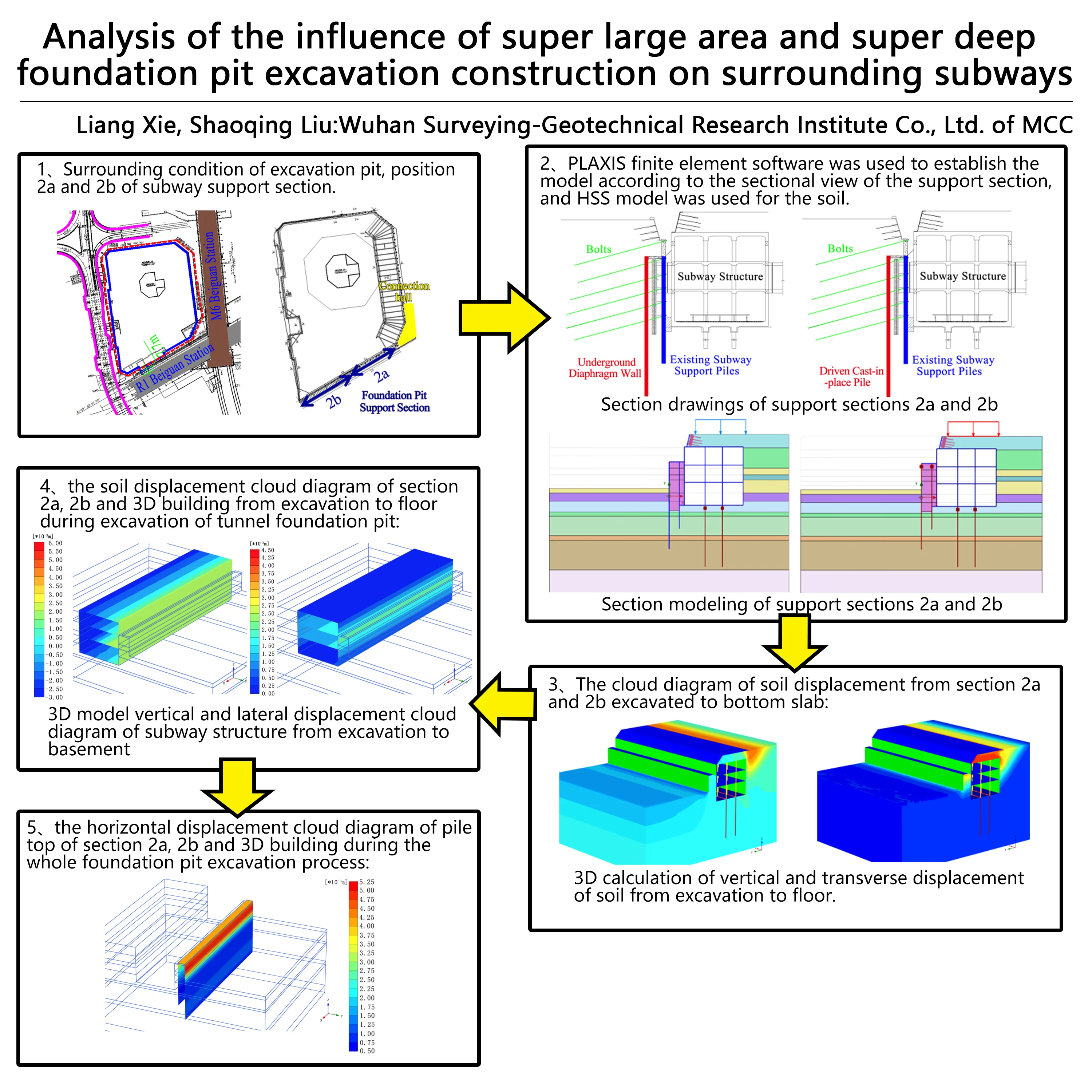
The project is located in Tongzhou District, Beijing, with a total construction land area of 58,520m2. The plot is adjacent to Tongzhou Beiguan Station of Metro Line M6 in the east, Tongzhou Beiguan Station of Metro R1 Line in the south, the Ring Tunnel in the west, and the C4 Exit and R4 Entrance of the Ring Tunnel in the north, as shown in Fig. 1.
Fig. 1The relationship between the location of the plot and the surrounding environment
The plot of this project is a complex of office, hotel and apartment buildings. The tower building has 61 floors above ground, with a building height of about 275 m and 4 floors underground, the podium building has 3 floors above ground, with a building height of about 18.0 m and 4 floors underground, the pure underground garage is divided into three floors underground. layer consideration. The trough bottom elevation in the podium area of this project is considered as –22.00 m, and the trough bottom elevation in the tower area is considered as –24.00 m, which is an ultra-deep large foundation pit.
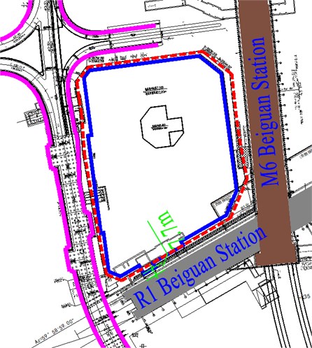
According to the progress of the project, the characteristics and difficulties of the project's foundation pit engineering, etc., this paper mainly studies the influence of the foundation pit excavation on the subway structure of Beiguan Station of the R1 line on the south side: the calculation and verification of the envelope structure of the foundation pit project is limited. Element software establishes the foundation pit support system and the two-dimensional model of the subway station, and simulates and evaluates the impact of the foundation pit excavation on the structural deformation of the subway station through finite element numerical analysis. Among them, the sideline of the basement structure is 7.7 m away from the nearest station, and the main structure of the station is buried at a depth of about 30.5 m.
Beiguan Station is an underground three-story island station. The main structure is a three-story, two-column, three-span frame structure. The total length of the station is 289.1 m, the platform width is 15.0 m, the line spacing is 18.2 m, the structure covering soil is about 4.3 m, and the station floor is buried deep. About 27.8 m. Based on the integrated design of Beiguan Station, connecting halls are set up in the northeast and northwest quadrants of the transfer node between the station and the M6 line Beiguan Station.
2.2. Geological conditions
The investigation report reveals that the interior layer with a depth of 137 m is composed of artificial fill soil, newly deposited soil and quaternary Holocene fluvial and lacustrine sediments. The lithology is mainly filled soil, cohesive soil, silty soil and fine medium sand with gravel locally. The main stratigraphic parameters and sections are shown in Table 1 and Fig. 2 respectively. Geomologically, the proposed site belongs to the middle and lower part of alluvial fan of Wenyu River. The shallow groundwater in the site is the pore phreatic and confined water of quaternary unconsolidated layer, and the buried depth of initial water level is 9.50-11.40 m, and the buried depth of stable water level is 9.90-11.70 m. The water in this layer mainly occurs in the third layer (3) of fine sand and gravel, the fourth layer (4) of fine and medium sand, and the fifth layer (5) of fine and medium sand.
Table 1Selection of soil parameters
Formation | (kN/m3) | (MPa) | (kPa) | (o) | (m/d) |
(1) Miscellaneous fill | 17.5 | – | 0 | 10 | – |
(2)-1 Clay silt, sandy silt | 19.5 | – | 15 | 25 | 0.05 |
(2)-2 Silty clay, heavy silty clay | 19.0 | – | 24 | 10 | 0.002 |
(2)-3 Clayey silt, sandy silt | 20.0 | – | 12 | 24 | 0.05 |
(2)-4 Silty-fine sand | 20.0 | – | 0 | 27 | 20.0 |
(3) Fine sand contains pebbles | 20.0 | 25 | 0 | 30 | 25.0 |
(3)-1 Gravel sandwiched with fine medium sand | 20.0 | 30 | 0 | 32 | 45.0 |
(4) Fine medium sand | 20.0 | 35 | 0 | 30 | 20.0 |
(4)-1 Heavy silty clay, silty clay | 19.1 | 12.87 | 25 | 7 | 0.002 |
(5) Fine medium sand | 20.0 | 45 | 0 | 35 | 20.0 |
Note: – bulk density, – modulus of compressibility, – cohesion, – internal friction angle, – coefficient of permeability | |||||
2.3. Foundation pit supporting design scheme
Considering different conditions such as structural design conditions, geological conditions of various parts of the foundation pit, and support forms, the project is divided into two support sections 2(a) and 2(b).
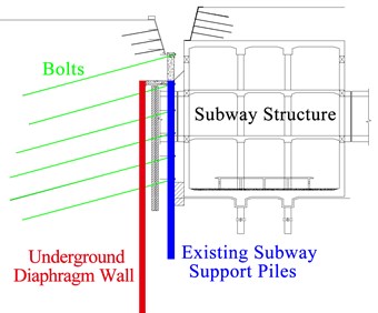
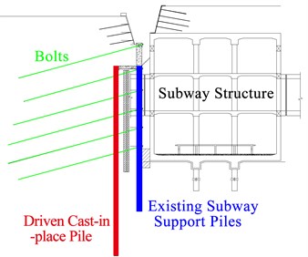
(1) The support system of “double row pile + prestressed anchor bolt” is adopted in the support section of 2A, in which the front pile is replaced by underground continuous wall with wall thickness of 0.8 m, length of 35.50 m and embedded depth of 24.7 m, The back pile adopts the original subway supporting structure, with diameter of 1.0 m, spacing of 1.6 m, length of 27.2 m and embedded depth of 16.4 m.
(2) The supporting system of "double row pile + prestressed bolt" is adopted in the 2b support section, in which the front pile adopts cast-in-place pile, with pile diameter of 1.0 m, spacing of 1.6 m, length of 35.50 m and embedded depth of 24.7 m. The back pile adopts the original subway supporting structure, with diameter of 1.0 m, spacing of 1.6 m, length of 27.2 m and embedded depth of 16.4 m.
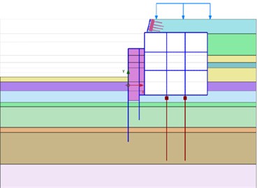
Fig. 2Support section drawings of 2a and 2b
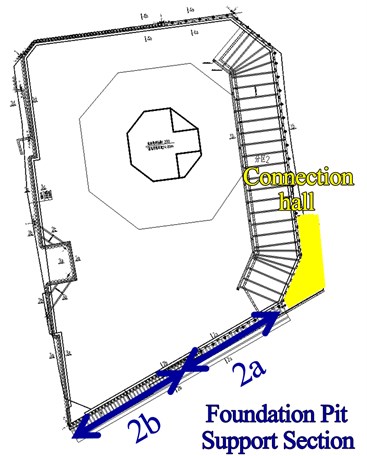
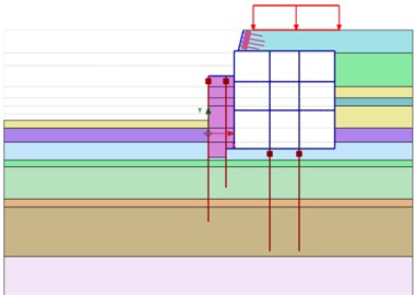
Fig. 3Section drawings of support sections 2a and 2b
a) 2a
b) 2b
2.4. Groundwater control system
The foundation pit of this project adopts water stop scheme. Within 50 m from the subway, underground continuous wall water stop curtain is adopted. The width of underground continuous wall is 800 mm, and the joint of underground continuous wall is blocked by high-pressure rotary jet pile. 50 m away from the grouting pile + piles between the double high pressure rotary jet grouting pile sealing curtain, the pit is equipped with dredging Wells, with a depth of 30 m and a spacing of 20 m. Emergency precipitation Wells are set outside the pit, with a depth of 25 m for type 1 on the west side, 35 m for type 2 on the north side and east side, and the spacing of precipitation Wells is 8.8 m.
2.5. Design parameters and strength standards
1. Design water level: –11.70 m (absolute elevation 13.50 m).
2. Ground overload outside the pit: no pile load shall be allowed within 2 m of the top of the slope, and 30 kPa beyond 2 m, Additional loads on other parts should be considered according to actual conditions.
3. Design strength:
(1) Cement: P.O 42.5 ordinary Portland cement.
(2) Bored pile: the design strength grade of reinforced concrete pile is C25, and the crown beam is the same as the reinforced concrete pile.
(3) Underground continuous wall: the concrete design strength grade is C30 underwater, and the crown beam is connected with the ground wall, Wall concrete impermeability grade P6.
(4) High pressure rotary jet grouting pile: the cement content is 25 %, and the unconfined compressive strength is 1.2 mpa in 28 days.
(5) Double high pressure rotary jet grouting pile: cement content 35 %, 28 days unconfined compressive strength 1.2mpa.
(6) Steel strand: 1×7, Øs/15.2.
(7) Steel bar: HPB300 grade steel bar, HRB335 grade steel bar, HRB400 grade steel bar.
(8) Inter-pile support: Shotcrete slope protection layer concrete strength grade C20.
3. Finite element analysis establishment
Before the project construction, PLAXIS finite element software of geotechnical engineering was used to analyze the research content. PLAXIS geotechnical products are the world's leading finite element software for geotechnical engineering, which is used to solve the problems of geotechnical engineering such as deformation, stability, seepage, consolidation, construction process simulation, dynamic analysis and so on.
The HSS model is adopted in this paper. The HS Small material model is a constitutive model based on the soil hardening model (HS), which considers the stiffness enhancement effect at the Small strain stage. It can simulate the behavior of different types of soil, including soft soil and hard soil. It is capable of simulating plasticity, creep, expansion, stress strengthening, large deformation and large strain. The HSS model is more suitable for this project. According to the actual working conditions, considering the influence of groundwater and space-time effect on the effective stress of soil around subway, the model is 100 m in width and 50 m in depth.
In the analysis model, the envelope design near the foundation pit was simplified according to the principle of stiffness equivalence. Plate element was used to simulate the envelope structure, n2nAnchor element was used to simulate the free section of anchor rod, and the EmbeddedPile element was used to simulate the grouting section of anchor rod. Soil element was used to simulate the reinforced Soil. The constraint conditions at the bottom of the model are fixed in both horizontal and vertical directions, while the constraint conditions on both sides are fixed in horizontal direction and free in vertical direction.
The value of soil strength index and permeability coefficient is taken as the geological report. The deformation modulus of all kinds of soil takes into account the influence of stress path, and the unloading modulus is:
where – deformation modulus, MPa, – influence coefficient of stress path corresponding to deformation modulus, – effective weight of soil, – depth.
4. Analysis of the influence of foundation pit excavation on south R1 metro line
4.1. Finite element analysis modeling
Finite element analysis models of support sections 2a and 2b were established in PLAXIS according to the sectional drawing of adjacent subway LINE R1, as shown in Fig. 4.
Fig. 4Section and finite element model of support section 2a and 2b
a) Section view of 2a support section
b) Section view of 2b support section
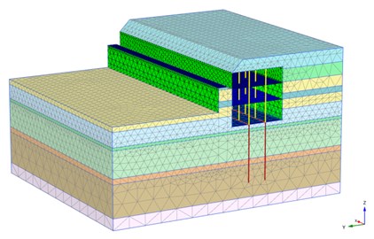
c) 3D calculation model of support section
4.2. Finite element calculation results
4.2.1. Calculation results of soil deformation
Figs. 5-6 shows the cloud diagram of soil displacement from section 2a and 2b excavated to bottom slab.
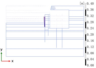
Fig. 5Cloud map of soil displacement from excavation to bottom slab in section 2a
a)
b)
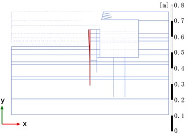
Fig. 6Cloud map of soil displacement from excavation to bottom slab in section 2b
a)
b)
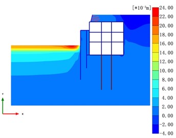
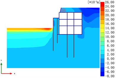
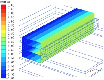
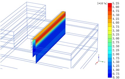
Fig. 73D cloud diagram of soil displacement from excavation to bottom slab
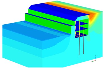
a) Vertical (Max.: 26.4 mm)
b) Horizontal (Max.: 14.2 mm)
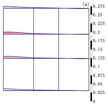
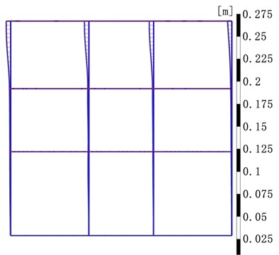
Fig. 5 shows that the maximum horizontal displacement of section 2a is 6.2 mm, and the maximum vertical displacement is 23.5 mm and –3.7 mm in the process of soil excavation to the bottom plate. Fig. 6 shows that the maximum horizontal displacement of section 2b is 10.0 mm, and the maximum vertical displacement is +24.0 mm and –7.0 mm. It can be seen from Fig. 7 that the maximum horizontal and lateral displacement is 14.2 mm and the maximum vertical displacement is 26.4 mm in 3D calculation.
4.2.2. Calculation results of subway station structure
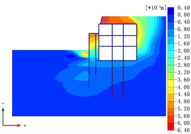
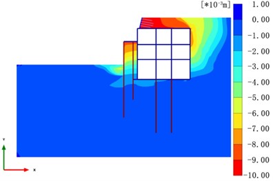
Figs. 8-10 is the soil displacement cloud diagram of section 2a, 2b and 3D building from excavation to floor during excavation of tunnel foundation pit.
Fig. 8Cloud map of subway structure displacement from section 2a excavation to basement
a)
b)
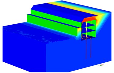
Fig. 8 shows that the maximum horizontal displacement of section 2a is 4.7 mm, and the maximum vertical displacement is +6.0 mm and –1.0 mm in the process of excavation. Fig. 9 shows that the maximum horizontal displacement of section 2b is 4.9 mm, and the maximum vertical displacement is +6.3 mm and –1.1 mm. It can be seen from Fig. 10 that the maximum horizontal and lateral displacement is 4.4 mm and the maximum vertical displacement is 5.9 mm and –2.7 mm in 3D calculation.
Fig. 9Cloud map of subway structure displacement from section 2b excavation to basement
a)
b)
Fig. 10Cloud map of subway structure displacement from excavation to basement of 3D model
a) Vertical
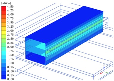
b) Horizontal
4.2.3. Calculation results of pile top deformation
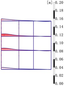
Fig. 11 is the horizontal displacement cloud diagram of pile top of section 2a, 2b and 3D building during the whole foundation pit excavation process.
Fig. 11 shows that during the whole excavation process, the maximum horizontal displacement of the top of the diaphragm wall in section 2A is about 5.1 mm, and the maximum horizontal displacement of the top of the retaining pile in section 2B is about 8.2 mm. The maximum horizontal displacement of the retaining pile is about 5.0 mm.
4.3. Deformation affects the results
The deformation control requirements of station structure of R1 line are shown in Table 2.
Based on finite element calculation, the deformation results are shown in Table 3.
Fig. 11Horizontal displacement of pile top
a) Section 2a
b) Section 2b
c) 3D models
Table 2Structural deformation control requirements of R1 line station
Structural deformation | Deformation cracks | Differences in deformation | |||
Vertical | Horizontal | Horizontal | Vertical | ||
Deformation control requirements | ≤ +10 mm, –5 mm | ≤ 5 mm | The vertical deformation difference on both sides of the deformation joint is no more than 1.5 mm | The vertical differential deformation between the same span side wall and the central column or between the central column and the central column is not more than 5 mm | The vertical differential deformation of 20m is no more than 5mm |
Finite element analysis value | ≤ 6.3 mm ≤ –2.7mm | ≤ 4.9 mm | – | ≤ 4.7 mm | ≤ 1.7 mm |
Table 3Deformation statistics of finite element calculation
Deformation | ||||||
Calculation model | Maximum horizontal deformation of soil (mm) | Maximum vertical deformation of soil (mm) | Maximum horizontal deformation of structure (mm) | Maximum vertical deformation of structure (mm) | The pile top is deformed horizontally (mm) | |
Line R1 | 2a Section | 6.2 | 23.4 | 4.7 | 6.0, –1.0 | 5.1 |
2b Section | 10.0 | 24.0 | 4.9 | 6.3, –1.1 | 8.2 | |
3D Model | 14.2 | 26.4 | 4.4 | 5.9, –2.7 | 5.0 | |
5. Conclusions
1) Due to the large excavation area of the foundation pit and the close distance between the foundation pit and Beiguan station of R1 metro line, the unloading effect caused by large excavation results in a tendency of the soil outside the pit to move inside the pit. Under the influence of the soil deformation transfer effect, the Beiguan station of R1 metro line has a certain rebound, settlement and horizontal displacement.
2) The finite element analysis results show that the Beiguan station of metro Line R1 has certain springback deformation, additional settlement and horizontal displacement in the process of foundation pit excavation, but the values of each deformation index are within the deformation control standard, in line with the corresponding evaluation standard, the structure is safe and the project is feasible.
3) The excavation process of the foundation pit has a certain influence on the deformation of the main body of the subway station and the structure of the ring tunnel due to the close distance between the subway station and the tunnel, so the deformation monitoring should be strengthened in the construction process, and the earthwork excavation should be carried out strictly in accordance with the design scheme of the foundation pit support.
4) The numerical analysis considering the influence of soil small strain can better reflect the influence of foundation pit excavation on the displacement, deformation and internal force of the existing structure, and the calculated results are in better agreement with the actual engineering experience. However, due to the characteristics of finite element model and soil constitutive relationship, the calculated value and influence range may be different from the actual value. Therefore, although the calculation results are quantitative calculation, they are qualitative reference.
5) Foundation pit construction shall be carefully constructed, and the quality of foundation pit construction shall be strictly controlled to ensure the safety of foundation pit, The deformation of foundation pit is strictly controlled to reduce the additional deformation of subway station and tunnel. During the construction process, the construction load between the roof of the subway station, the tunnel and the envelope structure is strictly controlled.
6) Dewatering tests should be carried out before foundation pit dewatering construction to accumulate experience. Meanwhile, feasible, operable and feasible emergency plans should be formulated to prevent sudden water seepage and water inrush accidents. Corresponding emergency supplies should be in place. Avoid precipitation outside the subway side foundation pit as far as possible.
References
-
H. Sun, Y. Chen, J. Zhang, and T. Kuang, “Analytical investigation of tunnel deformation caused by circular foundation pit excavation,” Computers and Geotechnics, Vol. 106, pp. 193–198, Feb. 2019, https://doi.org/10.1016/j.compgeo.2018.11.001
-
Z. G. Zhang, M. X. Zhang, and W. D. Wang, “Two stage method for analyzing effects on adjacent metro tunnels due to foundation pit excavation,” (in Chinese), Rock and soil Mechanics, Vol. 32, No. 7, pp. 2085–2092, 2011.
-
Xuemin Zhang, X. Ou, Junsheng Yang, and Jinyang Fu, “Deformation response of an existing tunnel to upper excavation of foundation pit and associated dewatering,” International Journal of Geomechanics, Vol. 17, No. 4, p. 04016112, 2016.
-
X. Huang, H. W. Huang, and D. M. Zhang, “Longitudinal deflection of existing shield tunnels due to deep excavation,” (in Chinese), Chinese Journal of Geotechnical Engineering, Vol. 34, No. 7, pp. 1241–1249, 2012.
-
Y. W. Zhang, Y. L. Xie, and M. S. Weng, “Centrifugal test on influence of asymmetric foundation excavation to an underlying subway tunnel,” Rock and Soil Mechanics, Vol. 39, No. 7, pp. 2555–2562, 2018.
-
C. W. W. Ng, J. W. Shi, and Y. Hong, “Three-dimensional centrifuge modelling of basement excavation effects on an existing tunnel in dry sand,” Canadian Geotechnical Journal, Vol. 50, No. 8, pp. 874–888, 2013.
-
X. Hu, “Model Test to Simulate the influence of foundation pit excavation on existing tunnels under different conditions,” (in Chinese), Subgrade Engineering, Vol. 6, pp. 151–155, 2015.
-
R. P. Chen et al., “Considerable displacement and protective measures for metro tunnels adjacent large excavation,” Journal of Zhejiang University: Engineering Science, Vol. 50, No. 5, pp. 856–863, 2016.
-
R. Chen, F. Meng, Z. Li, Y. Ye, and J. Ye, “Investigation of response of metro tunnels due to adjacent large excavation and protective measures in soft soils,” Tunnelling and Underground Space Technology, Vol. 58, pp. 224–235, Sep. 2016, https://doi.org/10.1016/j.tust.2016.06.002
-
D. J. Zuo et al., “Numerical analysis of influence of deep excavations on adjacent subway tunnels,” (in Chinese), Chinese Journal of Geotechnical Engineering, Vol. 36, pp. 391–395, 2014.
-
B. Liu, D.-W. Zhang, C. Yang, and Q.-B. Zhang, “Long-term performance of metro tunnels induced by adjacent large deep excavation and protective measures in Nanjing silty clay,” Tunnelling and Underground Space Technology, Vol. 95, p. 103147, Jan. 2020, https://doi.org/10.1016/j.tust.2019.103147
-
Y. Tan, X. Li, Z. Kang, J. Liu, and Y. Zhu, “Zoned excavation of an oversized pit close to an existing metro line in stiff clay: case study,” Journal of Performance of Constructed Facilities, Vol. 29, No. 6, p. 04014158, Dec. 2015, https://doi.org/10.1061/(asce)cf.1943-5509.0000652
-
Z. Ding et al., “Measurement analysis on whole excavation of foundation pit and deformation of Adjacent metro tunnel,” (in Chinese), Rock and Soil Mechanics, Vol. 40, pp. 415–423, 2019.
About this article

