Abstract
In order to ensure that the gear of the steering component of the full-rotation propeller meets the limit of bearing capacity and normal use under the action of moment load, this paper takes a steering propeller device as the research object, establishes the finite element model of the gear of the steering component under normal and braking conditions, carries out stress bending strength analysis, and carries out modal analysis. It is verified that the gear of the steering assembly meets the safety requirements, which provides a reference for the design of the steering device.
1. Introduction
Full-rotation propeller is a new type of marine propeller which can rotate 360° around the longitudinal axis and propel in any direction [1]. The key component to realize 360° rotation of the full swing propeller is the gear of the steering assembly. In different working conditions, the loads on the gear of the steering assembly are also different, so it is necessary to check and analyze the strength of the gear under different working conditions. In addition, in order to prevent the resonance phenomenon in the process of gear meshing, the modal analysis of gear meshing is carried out to verify whether it meets the working performance.
The finite element analysis method is mostly used to check the strength of gears. Li Shunde et al., Ordnance Engineering College, obtained the dynamic nephogram and meshing force curve of gear meshing based on ANSYS/LS-DYNA [2]. Li Yan et al., School of Mechanical Engineering, Tongji University, obtained the stress nephogram of gear and rack under the maximum meshing force through ANSYS software [3]. He Qu, He Jingliang, etc. studied the main factors affecting the meshing quality such as gear force and tooth surface contact under actual working conditions [4]. Tang Min studied the design check and finite element analysis of the gear pair of the power head of the full hydraulic tunnel drilling rig [5]. Guo Lihong of Chengdu Jincheng University and others studied the finite element analysis of wind power yaw gear [6].
The meshing of gears will produce vibration. When the vibration reaches a certain amplitude and is close to its own excitation frequency, the structure will resonate, which will easily lead to the destruction of the structure. How to reduce the vibration can be achieved by optimizing the gear tooth profile and gear meshing. In addition, it is also necessary to rule out whether there is a crack in the gear; when there is a crack in the gear, the vibration generated in the process of gear meshing is more likely to cause structural damage [7-8].
In this paper, the finite element analysis software ANSYS workbench is used to analyze whether the steering gear meets the load capacity limit and the normal use limit under different working conditions, and the modal analysis is carried out to analyze the possibility of resonance, which provides support for the design of steering gear.
2. Modeling analysis and check of gear
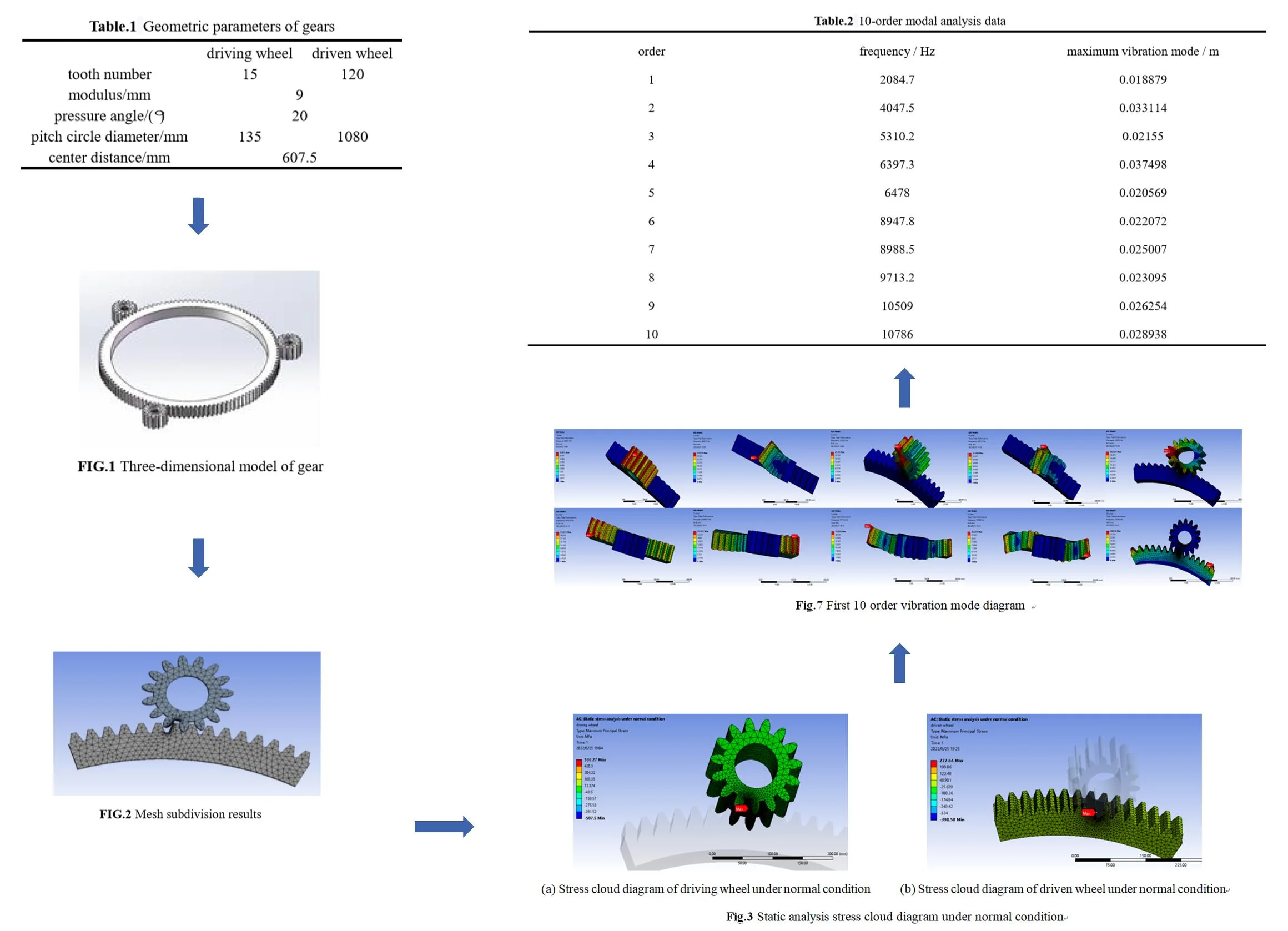
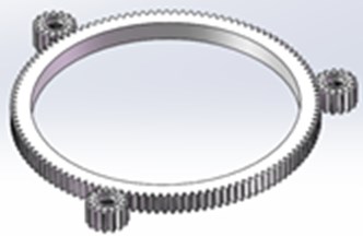
Gear solid model parameters are shown in Table 1, modeling by SolidWorks 3D software is shown in Fig. 1.
Table 1Geometric parameters of gears
Driving wheel | Driven wheel | |
Tooth number | 15 | 120 |
Modulus / mm | 9 | |
Pressure angle / (°) | 20 | |
Pitch circle diameter / mm | 135 | 1080 |
Center distance / mm | 607.5 | |
Fig. 1Three-dimensional model of gear
Under normal working condition, the maximum torque required for steering is 75444 N.m, and under braking condition, the load torque of the driving wheel is 8830 N.m; under ideal conditions, the circumferential forces borne by the tooth surface of the gear are:
where – indexing circle diameter of driving wheel; – torque of the driving wheel under normal conditions; – circumferential force on gear tooth surface under normal conditions; – torque of driving wheel under braking condition; – circumferential force on gear tooth surface under braking condition.
Calculation formula of bending strength of gear tooth root:
The maximum bending stress of the driving wheel and the driven wheel teeth can be calculated.
By looking up the “mechanical design manual” use coefficient is 1.25; dynamic load coefficient takes 1.1; the tooth load distribution coefficient is 1.2; the load distribution coefficient between teeth is 1; the composite tooth profile coefficient of the driving wheel is 4.42; the composite tooth profile coefficient of driven wheel is 3.96; the coincidence degree and spiral angle coefficient take 1; gear modulus take 9;driving wheel tooth width takes 80 mm; driven wheel tooth width take 71 mm; through the calculation formula of tooth root bending strength, the bending stress of the driving wheel under normal working conditions is 471.7 MPa, and the bending stress of the driven wheel is 476.2 MPa. Under braking condition, the bending stress of driving wheel is 853.3 MPa and that of driven wheel is 861.4 MPa.
Calculation formula of allowable bending stress according to materials:
The allowable bending stress of the gear teeth of the driving wheel and the driven wheel can be calculated.
By looking for the “mechanical design manual” master-slave gear material bending fatigue limit basic value , take 620 MPa; the life coefficient and of the bending strength of the driving and driven wheels are both 2.5; relative root fillet sensitivity coefficient is 1; relative tooth root surface condition coefficient is 1; the size coefficients and of the bending strength calculation of the master and slave wheels are 0.95; the allowable bending stress of driving gear and driven gear is 920 MPa by the formula of allowable bending stress of gear teeth.
In summary: the driving wheel and the driven wheel meet the bending fatigue strength requirements under normal and braking conditions.
3. Gear finite element analysis
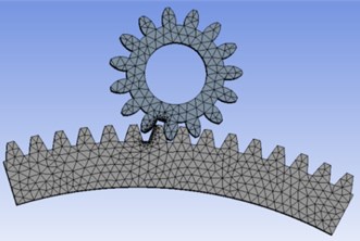
3.1. Mesh subdivision
The finite element analysis of the studied gear is carried out. The driving and driven wheels are made of alloy steel with elastic modulus of 2.06×10⁵ MPa and Poisson’s ratio of 0.3, and the density is 7850 kg/m3. Considering the actual working conditions, the static calculation and analysis of the normal working conditions are taken, and the transient calculation and analysis of the braking conditions are taken. Considering the calculation efficiency, one of the driving wheels is taken, and one eighth of the driven wheel is intercepted for calculation. At the same time, the gear meshing adopts local mesh encryption processing. The number of nodes after meshing is 128571, and the unit is 82392, as shown in Fig. 2.
Fig. 2Mesh subdivision results
3.2. Loads analysis
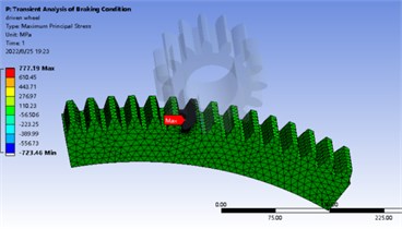
In normal static calculation, 3143.5 N. m is added to the center of driving wheel and the center of driven wheel is fixed. The maximum bending stress appears near the tooth root, the stress of driving gear is 536.3 MPa, the strain is 2.0035×10⁻⁶, the stress of driven gear is 272.6 MPa, the strain is 1.9692×10⁻⁶. The stress and strain distribution is shown in Fig. 3 and Fig. 4. In the transient analysis of braking condition, 5686.5 N.m is added to the center of the driving wheel and 0.2 rad/s is added to the driven wheel. The maximum bending stress appears near the tooth root. The stress value of the driving wheel is 726 MPa and the strain value is 2.7504×10⁻⁶. The stress value of the driven wheel is 777 MPa and the strain value is 3.6231×10⁻⁶. The stress-strain distribution cloud diagram is shown in Fig. 5 and Fig. 6. By comparing the analysis results and theoretical calculation results, the analysis results are close to the theoretical results, which are less than the allowable bending stress of 920 MPa.
Fig. 3Static analysis stress cloud diagram under normal condition
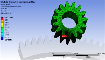
a) Stress cloud diagram of driving wheel under normal condition
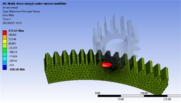
b) Stress cloud diagram of driven wheel under normal condition
Fig. 4Static analysis strain cloud diagram under normal condition
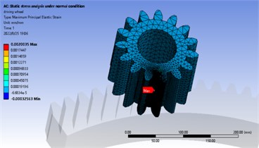
a) Strain cloud diagram of driving wheel under normal condition
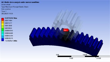
b) Strain cloud diagram of driven wheel under normal condition
Fig. 5Static analysis stress cloud diagram under braking condition
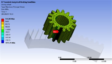
a) Stress cloud diagram of driving wheel under braking condition
b) Stress cloud diagram of driven wheel under braking condition
Fig. 6Static analysis strain cloud diagram under braking condition
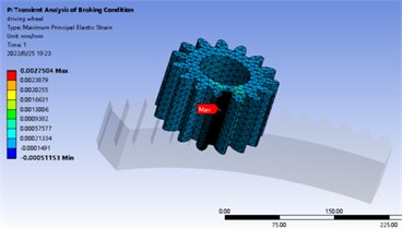
a) Strain cloud diagram of driving wheel under braking condition
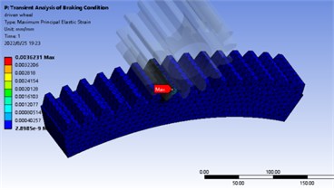
b) Strain cloud diagram of driven wheel under braking condition
4. Modal analysis
Vibration modes are inherent and integral characteristics of elastic structures. If the characteristics of the main modes of the structure in a certain vulnerable frequency range are made clear by modal analysis method, it is possible to predict the actual vibration response of the structure under the action of various external or internal vibration sources in this frequency range. Therefore, modal analysis is an important method for structural dynamic design and fault diagnosis of equipment [9-12].
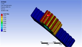
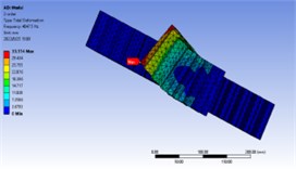
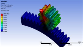
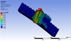
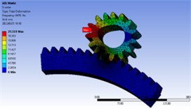
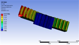
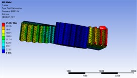
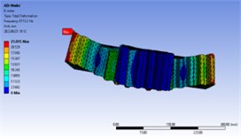
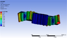
In order to further analyze whether there is resonance in the working process of the gear, the modal analysis of the gear is carried out, and the natural frequency and vibration mode of the first 10 orders are obtained as shown in Table 2 and Fig. 7.
Table 210-order modal analysis data
Order | Frequency / Hz | Maximum vibration mode / m |
1 | 2084.7 | 0.018879 |
2 | 4047.5 | 0.033114 |
3 | 5310.2 | 0.02155 |
4 | 6397.3 | 0.037498 |
5 | 6478 | 0.020569 |
6 | 8947.8 | 0.022072 |
7 | 8988.5 | 0.025007 |
8 | 9713.2 | 0.023095 |
9 | 10509 | 0.026254 |
10 | 10786 | 0.028938 |
Fig. 7First 10 order vibration mode diagram
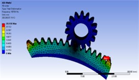
The meshing frequency of the gear at the maximum speed of 3000 rpm:
That is, the speed excitation range of gear is 0-750 Hz, and the range of the first 10 order natural frequency is 2000-11000 Hz, indicating that the natural frequency of gear is greater than the maximum excitation frequency.
5. Conclusions
According to the results of software analysis, compared with the theoretical calculation results, it is concluded that the stress bending strength of the rudder component gear meets the requirements of allowable bending strength under normal and braking conditions. In addition, the first 10 order mode shapes are obtained through the modal analysis of the rudder gear. The natural frequency is greater than the excitation frequency, and the possibility of resonance is very small. Therefore, the gear transmission is reliable, and also provides a reference for the design of the rudder device.
References
-
“An energy-saving and environment-friendly ship propulsion device – 360° full-rotation rudder propeller device,” (in Chinese), Jiangsu Ship, Vol. 3, pp. 5–21, 2004.
-
Li Shunde, Feng Guangbin, Sun Huagang, and Liu Jun, “Simulation analysis of typical gear faults based on ANSYS / LS-DYNA,” (in Chinese), New Technology and Process, Vol. 4, pp. 17–20, 2010.
-
Li Yan, Wang Jin, Xu Hao, Shi Wei, and Tan Xiuwen, “Modeling and simulation of automobile steering gear rack,” (in Chinese), Modern Manufacturing Engineering, Vol. 12, pp. 73–94, 2010.
-
He Qu, He Jingliang, He Changran, and Cai Pu, “Simulation analysis and modification optimization of spiral bevel gear transmission,” (in Chinese), Journal of Beijing University of Information Science and Technology (Natural Science Edition), Vol. 6, pp. 37–40, 2014.
-
Tang Min, “Design check and finite element analysis of power head gear pair of full hydraulic tunnel drilling rig,” (in Chinese), Coal Mine Machinery, Vol. 9, pp. 17–19, 2020.
-
Guo Lihong, Li Sanyan, and Hu Huayan, “Finite element analysis of wind power yaw gear,” (in Chinese), China Test, Vol. 5, pp. 156–162, 2022.
-
M. Er-Raoudi, M. Diany, H. Aissaoui, and M. Mabrouki, “Nonlinear dynamic analysis and defect detection of gears,” Journal of Mechanical Engineering, Automation and Control Systems, Vol. 3, No. 1, pp. 9–22, Jun. 2022, https://doi.org/10.21595/jmeacs.2022.22374
-
A. Czakó, K. Řehák, A. Prokop, and V. Ranjan, “Determination of static transmission error of helical gears using finite element analysis,” Journal of Measurements in Engineering, Vol. 8, No. 4, pp. 167–181, Dec. 2020, https://doi.org/10.21595/jme.2020.21825
-
M. V. B. Santana, M. Hjiaj, and P. Z. Berke, “Modal analysis of a bistable deployable module with a refined joint model,” Engineering Structures, Vol. 269, p. 114798, Oct. 2022, https://doi.org/10.1016/j.engstruct.2022.114798
-
J. Wu, V. Ondra, J. Luebker, S. Kalow, J. Riemenschneider, and B. Titurus, “Experimental modal analysis of a rotating tendon-loaded helicopter blade demonstrator,” Mechanical Systems and Signal Processing, Vol. 178, p. 109286, Oct. 2022, https://doi.org/10.1016/j.ymssp.2022.109286
-
M. Shariati, S. S. M. N. Souq, and B. Azizi, “Surface – and nonlocality-dependent vibrational behavior of graphene using atomistic-modal analysis,” International Journal of Mechanical Sciences, Vol. 228, p. 107471, Aug. 2022, https://doi.org/10.1016/j.ijmecsci.2022.107471
-
B. Ordonneau et al., “A simplified modal analysis of a single lap bonded joint using the macro-element technique,” International Journal of Solids and Structures, Vol. 249, p. 111631, Aug. 2022, https://doi.org/10.1016/j.ijsolstr.2022.111631
About this article

