Abstract
As a new type of flexible retaining structure, reinforced soil retaining wall is widely used in civil engineering and highway engineering because of good seismic performance and economy. The residual displacement under seism is one of the most important parameters to evaluate the seismic performance of reinforced soil retaining wall. The related theoretical research is rare. Taking the pseudo-dynamic method and kinematic differential equation as the theoretical basis, considering the residual deformation under large magnitude, a theoretical method is proposed to calculate the residual displacement of reinforced soil retaining wall under seismic. The rationality and accuracy of the theoretical method is verified by centrifuge model test. The results would provide some reference for the performance design and damage evaluation of reinforced soil retaining wall.
1. Introduction
Reinforced soil retaining wall has good seismic performance in engineering application, and its post-earthquake damage degree is far less than the traditional gravity retaining structure [1]. Due to the superiority seismic performance, reinforced soil retaining wall has been widely used. The failure modes of reinforced earth retaining wall under seism are various, among which the horizontal residual displacement is the most common. During the 1994 Northridge earthquake in the United States, the Valencia reinforced soil wall only cracked at the top of the wall under an earthquake with a peak seismic acceleration of 0.5 g, and there was no obvious deformation or displacement on the wall surface [2]. In the 1995 Kobe earthquake, a horizontal residual displacement of about 20 cm occurred on the top of the reinforced soil retaining wall of Tanata [3-4].
Thus, as a common seismic response of reinforced soil retaining wall, the in-depth study of horizontal residual displacement is particularly important. The calculation theory of post-earthquake residual displacement of reinforced soil retaining wall based on pseudo-dynamic method and kinematic differential equation is established. The correctness of the theory is verified by comparing with the centrifuge model test.
2. Methodology
2.1. Assumptions
The following assumptions are made to calculate the reinforcement load under horizontal seism:
(a) Residual deformation is mainly caused by the back filling of the wall, ignoring the residual deformation caused by the creep of the reinforcement in the reinforced area.
(b) Calculate the reinforced area homogeneously.
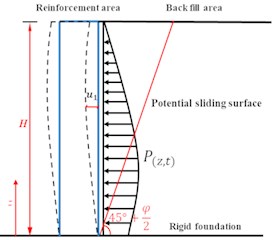
(c) The potential sliding surface of the back filling area is considered as Rankine straight line.
The calculation diagram is shown in Fig. 1.
Fig. 1Residual deformation after earthquake
2.2. Theoretical calculation
Based on the assumption (c), the dynamic earth pressure of the reinforced soil retaining wall in earthquake could be calculated as:
where is the response acceleration. Through the pseudo-dynamic method [5], it would be calculated as:
where is the height of the wall; is the height from the foundation; is the acceleration amplification coefficient; is the horizontal acceleration coefficient; is the seismic period, is the filling weight; is the angle between the potential slip surface behind the wall and the horizontal ground; is the time; is the angle between the resultant force of earth pressure and the horizontal direction, without considering the vertical earthquake; . is the velocity of the seismic wave propagation.
Since the soil will not transmit the tension force, the earth pressure behind the wall may be less than 0 when the response acceleration direction points inward. At this time, the backfill behind the wall contacts with the retaining wall without effect. When 0, let 0; when 0, the critical horizontal acceleration is:
In earthquake, the reinforced soil retaining wall is not only subjected to the dynamic earth pressure of the backfill, but also to the seismic inertial force. The force is shown in Fig. 2.
The seismic inertia force of the reinforced unit can be calculated as:
where is the laying length of reinforcement; is the spacing of reinforcement, and is the backfill density.
Fig. 2Reinforcement area calculation unit
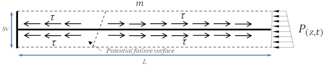
In earthquake, the horizontal interference force of the reinforced soil retaining wall units are the sum of the dynamic earth pressure behind the wall and the seismic inertia force of the units in the reinforced area, can be calculated as:
The movement of the reinforced soil retaining wall satisfies the kinematics equation:
where:, , is the damping ratio, measured by three-axis experiment; is the quality of the reinforcement units as shown in Fig. 3; is the self-circular frequency, and is the horizontal interference force.
The solution of Eq. (6) is:
The solution consists of two parts, one is the constant attenuation of free vibration, and the other is the stress vibration under the action of interference force. The stress vibration can be calculated as:
where , . When the magnitude is small, the motion equation would oscillate in a certain range. Because the soil cannot transfer tensile stress, when the magnitude is large, that is, 0, the displacement of outward motion in a single cycle is more than that of inward motion, leading to the residual displacement of the units. When 0, the residual displacement of a single period is the difference between inward and outward displacement, the residual displacement of a single period can be calculated as:
The post-earthquake residual displacement under multiple seismic cycles can be calculated as:
2.3. Parameter value
The natural frequency ω could be calculated as [6]:
where is the height of the retaining wall; is the quality of reinforced area of reinforced soil retaining wall; is the moment of inertia of the reinforced section of the retaining wall. The backfill spring stiffness could be calculated as [7]:
The whole shear modulus of reinforced area could be calculated as [8]:
where is the reinforcement thickness; is the reinforcement spacing; is the Poisson ratio of soil; is reinforcement Poisson ratio, and is the reinforcement elastic modulus. is the elastic modulus of soil, and can be calculate as [9]:
That:
where is the modulus number; is the modulus index; is the atmospheric pressure, and is the internal friction angle of soil.
3. Validation of the proposed method
To explore the displacement law of reinforced soil retaining wall in earthquake, multiple sets of centrifugal model tests were carried out by TSUJI [10]. The CASE4 condition is the equal length laying of the reinforced soil retaining wall with block panel. The similarity ratio of the model is 50, the centrifugal acceleration would load to 50 g before the seismic wave load. In this way, the experimental parameters are restored back to a gravity field, 1.3, 101.32 kPa, 0.5, 20.6 m, 16.6 m, 1144, 0.7, 1.2 m, 0.128, 40.6°, 5 mm, 1 s, 1592 kg/m3.
Taking the middle layer (10.3 m) and the top layer (17.6 m) for analysis, the theoretical calculation values of cumulative residual displacement for 20 cycles are compared with the experimental values of residual displacement after 20 s seismic condition. The comparison results ae shown in Fig. 3.
The theoretical value and experimental value of the cumulative residual displacement under different seismic peak acceleration are compared. After 20 seismic cycles, it can be found that the change of the experimental and theoretical values is the same. When the magnitude is smaller than 0.2 g, the cumulative residual displacement is basically zero. As the magnitude increases, there would be a critical point, and the cumulative speed of displacement after the critical point would improve rapidly.
At the horizontal acceleration less than 0.6 g, the theoretical and experimental values fit well. When 0.6 g, the experimental results show a trend of convergence. The reason is that with the magnitude and duration of the earthquake increase, the integrity of the reinforced soil retaining wall would gradually weaken. The energy will be consumed rapidly, and the final cumulative residual displacement will increase nonlinearly.
Fig. 3The comparison of cumulative residual displacement
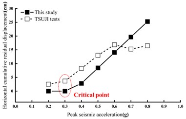
a) The comparison of cumulative residual displacement (10.3 m)
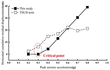
b) The comparison of cumulative residual displacement ( 17.6 m)
Fig. 4The comparison of critical horizontal acceleration coefficient
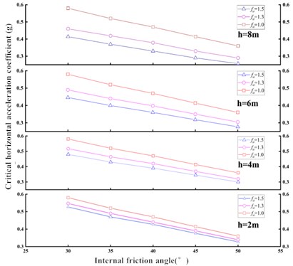
4. Parametric study
In this section, the results of a parametric study are reported to study the effects of and to the critical horizontal acceleration coefficient . The design conditions: 10 m, 0.13, 101.325 kPa, 0.5, 900, 7 m, 0.25 m, 1 s, 0.5, [0.2 g, 0.4 g, 0.6 g], 3 mm, 2000 kg/m3, [30, 35, 40, 45, 50], = [1.0, 1.3, 1.5], 0.7. The comparison results are shown in Fig. 4.
It can be known from the Fig. 4, if the acceleration amplification factor is not considered, for the same reinforced soil retaining wall, the critical horizontal acceleration of each layer is consistent. When the acceleration amplification factor is considered, as the wall height increases, the critical horizontal acceleration becomes smaller. By the way, the upper part of the retaining wall is more prone to the cumulative deformation in earthquake. When the height of the retaining wall and the considered acceleration amplification factor are consistent, with the increase of the internal friction angle of the fill, the retaining wall is more likely to produce cumulative deformation in earthquake.
5. Conclusions
The pseudo-dynamic method and kinematic differential equation is used to calculate the cumulative residual displacement. The following conclusions are drawn from the proposed method:
1. When 0.2 g, the residual displacement of the reinforced soil retaining wall almost hardly occur.
2. When 0.3 g, the residual displacement rises quickly.
3. The internal friction angle of the reinforced soil retaining wall has a significant effect on the critical horizontal seismic acceleration. Reducing the internal friction angle of the filling would patently slow down the cumulative residual deformation.
References
-
H. I. Ling, D. Leshchinsky, and N. N. S. Chou, “Post-earthquake investigation on several geosynthetic-reinforced soil retaining walls and slopes during the Ji-Ji earthquake of Taiwan,” Soil Dynamics and Earthquake Engineering, Vol. 21, No. 4, pp. 297–313, Jun. 2001, https://doi.org/10.1016/s0267-7261(01)00011-2
-
F. Tatsuoka, M. Tateyama, J. Koseki, and T. Uchimura, “Geotextile reinforced soil retaining wall and their seismic behavior,” in Proceedings of 10th Asian Regional Conference on Soil Mechanics and Foundation Engineering, Vol. 2, pp. 26–49, 1995.
-
R. J. Bathurst and Z. Cai, “Pseudo-static seismic analysis of geosynthetic-reinforced segmental retaining walls,” Geosynthetics International, Vol. 2, No. 5, pp. 787–830, Jan. 1995, https://doi.org/10.1680/gein.2.0037
-
D. Choudhury and S. S. Nimbalkar, “Pseudo-dynamic approach of seismic active earth pressure behind retaining wall,” Geotechnical and Geological Engineering, Vol. 24, No. 5, pp. 1103–1113, Oct. 2006, https://doi.org/10.1007/s10706-005-1134-x
-
S. S. Nimbalkar, D. Choudhury, and J. N. Mandal, “Seismic stability of reinforced-soil wall by pseudo-dynamic method,” Geosynthetics International, Vol. 13, No. 3, pp. 111–119, Jun. 2006, https://doi.org/10.1680/gein.2006.13.3.111
-
A. Ghanbari, E. Hoomaan, and M. Mojallal, “An analytical method for calculating the natural frequency of retaining walls,” International Journal of Civil Engineering, Vol. 11, No. 1, pp. 1–9, 2013.
-
A. S. Veletsos and A. H. Younan, “Dynamic modeling and response of soil‐wall systems,” Journal of Geotechnical Engineering, Vol. 120, No. 12, pp. 2155–2179, Dec. 1994, https://doi.org/10.1061/(asce)0733-9410(1994)120:12(2155)
-
G. Q. Yang, M. J. Zhou, and B. J. Zhang, “Study on the horizontal deformation of reinforced retaining walls of soils,” Chinese Journal of Rock Mechanics and Engineering, No. 7, pp. 1248–1252, 2005.
-
J. M. Duancan, “Strength, stress strain and bulk modulus parameters for finite element analyses of stresses and movements in soil masses,” Report No. UCB/GT/80-01, 1980.
-
S. Tsuji, N. Tatta, Zong-Jian Wang, and T. Kubo, “Seismic performance of geotextile reinforced soil wall with double facing system,” Geosynthetics Engineering Journal, Vol. 26, pp. 47–54, 2011.
About this article

Funding and support by the National Natural Science Foundation of China (Grant No. 52178314) and Graduate Science Research and Innovation foundation of Chongqing (Grant No. CYB22031).
The datasets generated during and/or analyzed during the current study are available from the corresponding author on reasonable request.
The authors declare that they have no conflict of interest.
