Abstract
Creep failure is one of the dominate failure mode for high temperature turbine blade during service. Under the tensile stress caused by large centrifugal force of the blade and the thermal stress and thermal softening of the material, the displacement as well as the creep strain and damage increase gradually. The present paper firstly gives the temperature field of the blade under typical service condition with numerical modelling. Then Norton’s creep constitutive relation and Lemaitre-Chaboche damage model are introduced into the finite element model, and three different working conditions are considered here to investigate its effect on creep service life of the turbine blade. Numerical results show that, the proposed numerical approach can predict the evolution of the creep process and the damage. Meanwhile, the introduction of cyclic factor is capable of reflecting the fatigue effect of cyclic load.
1. Introduction
With the development of modern aero-engine, the inlet temperature of the turbine blade becomes higher, and creep becomes one of the key inducements of the blade failure. Researchers had paid tremendous effort through theoretical, numerical and experimental investigations on this subject. In the past two decades there has been considerable progress and significant advances made in the development of fundamental concepts of damage mechanics and their application to solve practical engineering problems. For instance, new concepts have been effectively applied to characterize creep damage, low and high cycle fatigue damage, creep-fatigue interaction, brittle/elastic damage, ductile/plastic damage, strain softening, strain rate-sensitivity damage, impact damage, and other physical phenomena.
Sposito et al. [1] gave a critical review of the main results in the secondary and tertiary stages of creep, and discussed the advantages and disadvantages of each method. Hore and Ghosh [2] used continuum damage mechanics model to simulate creep behaviour of 2.25Cr-1Mo steel and developed a simple iteration scheme and optimisation procedure. Results showed that the numerical model compared well with experimental data. Maria and Kapil [3] discussed the physical mechanisms of the creep phenomenon in metals and the frameworks for modelling high temperature creep. They employed a hyperbolic sine model to fit the experimental creep data of ASTM A992 steel and illustrate the applications in high temperature creep buckling. Cui and Wang [4] proposed a phenomenological and a lifetime estimation model for steam turbine components, and the theoretical model is validated with experimental results of high-chromium 10%Cr stainless rotor steel. Wang et al. [5] proposed a model with both error-trained back-propagation artificial neural network (BP-ANN) and an improved method, and the model is validated with short term rupture life and related creep data obtained by creep experiments. Zhao et al. [6] proposed a novel damage constitutive model to predict creep deformation and damage evolution of nickel-based superalloyGH4169 based on TTC relations and continuum damage mechanics. Results showed that the proposed model could accurately predict the creep deformation, minimum creep rate, rupture time and damage evolution process of GH4169. Vito et al. [7] investigated the effect of a weaker heat of the wrought form of Haynes 282 nickel superalloy on creep rupture and maximum allowable working stress, and showed the importance of minimizing heat to heat variability of properties on high temperature creep strength. Teng [8] reviewed various thermo-based fatigue life prediction methods, and both theoretical background and experimental techniques are given. Michael et al. [9] used over 100 creep tests of a cast austenitic stainless steel and Larson-Miller model to predict long-term lifetimes as functions of temperature and stress, and results showed that the Larson-Miller approach is more robust when treating rupture-time datasets with wide experimental scatter.
The present paper focuses on the creep life prediction of a high temperature turbine blade under constant rotate speed, varying rotate speed and cyclic rotate speed to model different service conditions. Damage evolution and fatigue effect are also considered here.
2. Research method
The geometry model of the turbine blade investigated here is based on the NASA E3 (Energy Efficient Engine) high pressure turbine blade. Since only discrete outlines of three different sections of the turbine blade is available in literature, the geometry detail of the blade tip and the turbine disk are not considered here. The finite element model of the turbine blade is given in Fig. 1. Computational fluid dynamics is conducted to predict the temperature field of the turbine blade. The boundary condition for fluid flow and heat transfer analysis of the finite element model is given in Fig. 2. During the analysis, both the inlet and outlet are set as pressure boundary condition, the pressure and total temperature for inlet boundary are 2.06 MPa and 1700 K respectively, while for outlet boundary the pressure is 1.03 MPa. Heat loss at the tip and bottom of the blade model is neglect and adiabatic boundary condition is given here. Both sides of the computational model are periodic boundary condition. The cooling channel of the blade is given convective boundary condition, and the coefficient of convective heat transfer is 400 W/m2K, and the temperature of the cooling fluid is 600 K. The material of the turbine blade is GH4169.
Fig. 1Discretization of the turbine blade
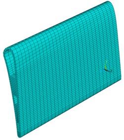
Fig. 2Boundary conditions for fluid flow and heat transfer analysis
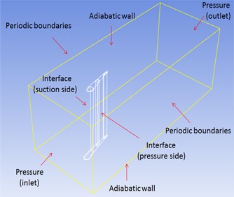
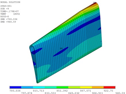
Fig. 3 shows the temperature field of the turbine blade under typical working condition. It can be seen that the temperature ranges from 780 K to 941 K, and the maximal temperature exists at the upwind area of the blade. The melting point temperature of GH4169 is about 1500 K, and generally speaking, when the temperature of the material is around 0.3 times of its melting temperature, creep becomes non-negligible. In the following section, creep analysis is conducted with the temperature field obtained here to investigate the service life of turbine blade under high temperature conditions.
Fig. 3Temperature field of the turbine blade
3. Results and discussion
In this section, three cases with different working conditions are employed to investigate the effect of working conditions on creep life of the turbine blade. The first case considers the constant rotate speed as well as constant centrifugal force of the turbine blade. The second case considers accelerating centrifugal force under thrust augmentation operation, and the third case considers the effect of cyclic centrifugal force.
During the first and second stage of creep, rate-dependent equation is always employed to characterize the creep process. In the present investigation, Norton creep model is adopted:
where is the rate of creep strain, , and are material constant to be determined by experiment, and they are 2.147×10-70.03, 10.171 and 50825.89 respectively in the present investigation. is stress and is temperature.
For stress-controlled interaction of creep and fatigue, creep damage can be modelled with Lemaitre-Chaboche damage model [10]:
where is creep damage, and parameter is related with creep stress:
where , , , , and are material constant to be determined by creep experiment, and they are 13.19, 1209 MPa, 13.2478, 0.7865×10⁻⁴, 0.1924×10⁻³ and 733.25 MPa respectively in the present investigation.
Creep damage is introduced into the finite element model throng the modification of Young’s modulus of the material:
where and denote the original and present Young’s modulus of the material.
For constant rotate speed case, the constant speed is 13223 rpm, and the bottom of the turbine blade is fixed during analysis, the temperature obtained in the previous section is applied in the finite element model. It is assumed that the maximal tolerate damage of the blade is 0.4, and when service time is 441 h, the maximal damage is 0.415, then the computation is terminated. The damage filed of the blade is given in Fig. 4, and the evolution of maximal damage of the blade during creep is given in Fig. 5.
Fig. 4Damage field of the turbine blade (after 441 h) at constant speed
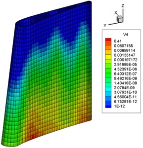
Fig. 5Evolution of maximal damage of the blade at constant speed during creep
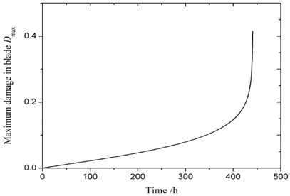
It can be seen from Fig. 4 and Fig. 5 that, at the beginning of creep, the damage in the blade increases linearly and slowly, when service time is 433 h and maximal damage is 0.23, the damage rate grows sharply and quickly reaches threshold value of 0.4.
Since turbine blade works at varying conditions, the rotate speed cannot be constant all the time. Case 2 considers the following varying speed of the turbine blade: the speed is constant at 0-50 h, and increase to 1.05 times of the first stage during 50 h- 70 h, then return to original constant speed during 70 h-120 h, and accelerate to 1.05 times of the first stage for the second time during 120 h-150 h, and then keeps at constant speed till the end. The time history of the rotate speed is shown in Fig. 6. Fig. 7 gives the evolution of maximal damage of the blade at varying speed during creep. It is very clear that with the increment of the rotate speed, as the centrifugal force increases at the same time, both the stress and the damage increase. When the rotate speed decreases to normal level, the damage decreases simultaneously. It also can be seen that the service life of the blade under this circumstance is 331 h, which is smaller than the previous constant rotate speed case.
Furthermore, the creep behaviour of the blade under cyclic rotate speed is considered. It should be pointed out that, experiments show that compared with constant rotate speed, the service life of the blade under cyclic rotate speed could be increase or decrease, which depends on the intrinsic character of the material. In the previous study, cyclic effect is always neglected, and it is introduced with factor v in the present study, and then the damage model is modified and given by:
where is cyclic factor and denotes the cycle number. When , the present model degrades into Eq. (2).
In the present study, the period of the rotate speed is 10 h, and in the first 5 h is constant rotate, while in the following 5 h the engine is shut down and the rotate speed is zero as shown in Fig. 8. Meanwhile, the thermal load is adjusted accordingly. When 0.1 %, the evolution of the maximal creep damage under cyclic condition is given in Fig. 9.
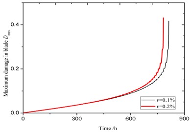
It can be seen from Fig. 9 that the service life of the blade is 800 h. Since the rest time and the working time are equal, then the actual service time is 400 h. Due to the effect of cyclic factor, it is smaller than the service time of case 1, which is 441 h. Fig. 10 also show the effect of the cyclic factor on the evolution of maximal creep damage. When the cyclic factor increase, the creep damage rate increases at the second stage of the creep, and the service life decrease. When cyclic factor increases from 0.1 % to 0.2 %, the service life decreases from 400 h to 385 h. The larger the cyclic factor is, the smaller the service life is.
Fig. 6Time history of the rotate speed of the turbine blade
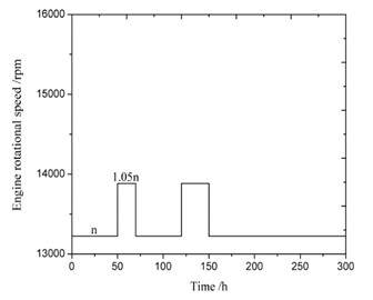
Fig. 7Evolution of maximal damage of the blade at varying speed during creep
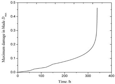
Fig. 8History of the rotational speed of the engine
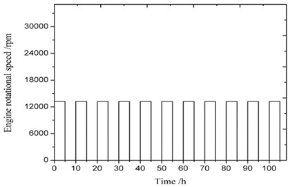
Fig. 9Evolution of maximal damage of the blade at cyclic rotate speed during creep
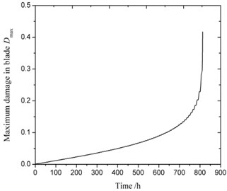
Fig. 10Effect of the cyclic factor on the evaluation of maximal creep damage
4. Conclusions
Numerical simulation of the creep behaviour of the turbine blade under different working condition is presented here. Creep damage is also considered through the modification of Young’s modulus of the material. Numerical results show that, the present approach can effectively predict the creep life of high temperature structure under both creep and creep-fatigue interaction. Although only Norton’s creep constitutive relation and Lemaitre-Chaboche damage model are considered here, the proposed numerical approach can easily extend to other creep and damage models, and provides a simple and effective approach to investigate the creep service life of high temperature structures.
References
-
G. Sposito, C. Ward, P. Cawley, P. B. Nagy, and C. Scruby, “A review of non-destructive techniques for the detection of creep damage in power plant steels,” NDT and E International, Vol. 43, No. 7, pp. 555–567, Oct. 2010, https://doi.org/10.1016/j.ndteint.2010.05.012
-
S. Hore and R. N. Ghosh, “Computer simulation of the high temperature creep behaviour of Cr-Mo steels,” Materials Science and Engineering: A, Vol. 528, No. 19-20, pp. 6095–6102, Jul. 2011, https://doi.org/10.1016/j.msea.2011.04.050
-
M. Cowan and K. Khandelwal, “Modeling of high temperature creep in ASTM A992 structural steels,” Engineering Structures, Vol. 80, pp. 426–434, Dec. 2014, https://doi.org/10.1016/j.engstruct.2014.09.020
-
L. Cui and P. Wang, “Two lifetime estimation models for steam turbine components under thermomechanical creep-fatigue loading,” International Journal of Fatigue, Vol. 59, pp. 129–136, Feb. 2014, https://doi.org/10.1016/j.ijfatigue.2013.09.007
-
L. Wang et al., “A creep life prediction model of P91 steel coupled with back-propagation artificial neural network (BP-ANN) and θ projection method,” International Journal of Pressure Vessels and Piping, Vol. 206, p. 105039, Dec. 2023, https://doi.org/10.1016/j.ijpvp.2023.105039
-
X. Zhao, X. Niu, Y. Song, and Z. Sun, “A novel damage constitutive model for creep deformation and damage evolution prediction,” Fatigue and Fracture of Engineering Materials and Structures, Vol. 46, No. 3, pp. 798–813, Nov. 2022, https://doi.org/10.1111/ffe.13896
-
V. Cedro, M. Render, and K. Chukwunenye, “Effect of heat-to-heat variability on long-term creep rupture lifetime predictions of single step aged wrought Haynes 282 alloy,” Journal of Pressure Vessel Technology, Vol. 145, No. 1, p. 01450, Feb. 2023, https://doi.org/10.1115/1.4056084
-
Z. Teng, “Thermo‐based fatigue life prediction: A review,” Fatigue and Fracture of Engineering Materials and Structures, Vol. 46, No. 9, pp. 3121–3144, Jun. 2023, https://doi.org/10.1111/ffe.14079
-
M. L. Santella et al., “Predicting the creep-rupture lifetime of a cast austenitic stainless steel using Larson-Miller and Wilshire parametric approaches,” International Journal of Pressure Vessels and Piping, Vol. 205, p. 105006, Oct. 2023, https://doi.org/10.1016/j.ijpvp.2023.105006
-
X. X. Liu, X. R. Zhang, X. J. Yan, and J. X. Nie, “The finite element analysis of HLCF life prediction for pm FGH95 based on damage mechanics,” (in Chinese), Journal of Aerospace Power, Vol. 18, pp. 101–108, 2003.
About this article

The authors have not disclosed any funding.
The datasets generated during and/or analyzed during the current study are available from the corresponding author on reasonable request.
The authors declare that they have no conflict of interest.
