Abstract
Isolation structures use high damping rubber bearings (HDRBs), lead rubber bearings (LRBs), and natural rubber bearings (NRBs) in order to significantly reduce the seismic forces transmitted from a substructure to a superstructure. The laminated rubber bearing is the most important structural member of a seismic isolation system. We present an analysis of a 1000 hr ongoing creep test conducted at 7.5 and 8.37 MPa in our laboratory. The long term behavior of bridge bearings (e.g., laminated rubber bearings) is determined through compression creep tests subjected to actual environmental conditions. These tests indicate that the maximum creep deformation is about 0.3 to 1.92 % of the total rubber thickness.
1. Introduction
A bridge bearing system must perform two functions: one is to resist vertical applied loads and deliver the loads to the substructure, and the other is to resist horizontal forces and displacements of the substructure and superstructure [1, 2]. These two functions are critical factors that are directly related to the horizontality of the bridge structure. In consideration of the durability of a laminated rubber bearing, the long term creep deformation made by rubber layers aging by oxidization and by axis compressive stress over the long term is very important [3]. However, in actual practice, it is hard to determine the necessary data, since creep deformation is influenced by the loading time of the bridge's upper structure and the temperature conditions [4]. Thus, the vertical deformation due to long term creep of a lead rubber bearing (LRB) is usually not considered during the design. Generally, the performance of a seismic isolation system such as a laminated rubber bearing is characterized by special tests such as a compressive test or compressive shear test on the material used in the bearing.
According to previous studies, creep tests have been performed on rubber test specimens which separated into chloroprene (CR) and natural rubber (NR) [5, 6]. However, the properties of a specimen’s rubber material can be analogized but cannot be defined as the estimation of the laminated rubber bearing. C. J. Deham and R. A. Waller have estimated 100 years of bearing life after creep deformation of a laminated rubber bearing designed to isolate buildings from subway vibration by measuring its deformation changes for 15 years [7]. However, this approach is not effective since it takes too much time to estimate the results by measuring data.
In the present research, a creep test was performed on three types of laminated rubber bearings such as high damping rubber bearings (HDRBs), lead rubber bearings (LRBs), and natural rubber bearing (NRBs) for 100 hr. The test result was used to analyze the creep properties of laminated rubber bearing. Also, we forecast the durable span of a structure after 60 and 100 yr of use [8]. It is necessary to clearly identify the properties of creep of a laminated rubber bearing under the high compression stress conditions of a real seismic isolation structure. In this regard, we estimated and analyzed long term deformation through creep tests according to the types of axis stress and laminated rubber bearings. After measuring the rubber’s expansion and compression with respect to temperature changes, the test results show that the amount of creep will not exceed 10 % of the total rubber thickness after 100 years of use.
2. Test specimens
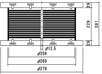
The HDRBs, LRBs, and NRBs used in the tests are seismic isolation system components, and are designed to match the dynamic characteristics of bridges and buildings. They are laminated with rubber and armature plates. The LRB has a lead plug installed in the center of specimen [9]. The HDRN and LRB dissipate energy in each cycle (EDC), but NRB has relatively EDC than above two specimens. The specimens used in the creep test and fatigue test are designed to satisfy various conditions: a serviceability limit state with respect to a design compression force, resistance against wind loads, and an ultimate limit state due to an earthquake. The specimens used in this research were manufactured as standard specimens per ISO 22762 [10]. The section shape and composition are shown in Fig. 1.
Fig. 1Inside section shapes of test specimens
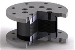
a) HDRB
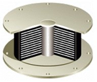
b) LRB
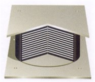
c) NRB
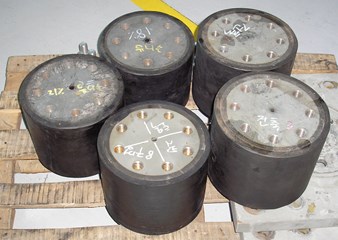
Fig. 2Specimen types

a) HDRB (No. 1, 2, and 3)
b) LRB (No. 4)
c) NRB (No. 5)
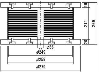
The specification and structure of test specimens are shown in Table 1 and Fig. 2. There is a difference in the size of the specimens, but their main material composition is natural rubber. As shown in Fig. 3, specimens No. 1, No. 2, and No. 3 are HDRBs that have a damping to the rubber itself. No. 4 is an LRB, which has lead insuled inside of a rubber bearing. Specimen No. 5. is a general NRB. The specimen’s diameter includes an outside rubber thickness of 10 mm, with inner layer laminated rubber thicknesses of 2 and 3 mm, and an inner laminated plate layer thickness of 3 mm. is the primary shape factor (the ratio of the load square to the free surface square, including one hole inside the rubber layer) [11]. is the secondary shape factor, which represents the effective width ratio versus the total thickness of the inner rubber layer [12]. Each shape factor was calculated as follows:
where is the diameter of the inner plate, is the diameter of the inner hole, is the thickness of a rubber layer, and is the number of rubber layers.
Table 1Specification of laminated rubber bearing
Specimen | Diameter (mm) | Rubber thickness (mm) | Number of layers | Axial stress (MPa) | Shear modulus () (GPa) | ||
No.1 | 250 | 2 | 25 | 29.7 | 5 | 7.5 | 0.8 |
No. 2 | 250 | 2 | 25 | 29.7 | 5 | 7.5 | 0.8 |
No. 3 | 250 | 2 | 25 | 29.7 | 5 | 7.5 | 0.4 |
No. 4 | 259 | 3 | 29 | 21.6 | 3 | 10.8 | 0.4 |
No. 5 | 269 | 3 | 31 | 16.6 | 2.8 | 8.4 | 0.4 |
HDRB: Nos. 1, 2, and 3. LRB: No. 4. NRB: No. 5. Note: the 10 mm thickness of a protection rubber layer is inclusive. | |||||||
Fig. 3Creep and fatigue test specimens
3. Test specimens
Fig. 4 A fatigue testing machine was used to perform the creep test on the laminated rubber bearings. The force displacement of the testing machine is a horizontal displacement of ±200 mm and the available vertical load is ±2000 kN. Deviation of the compressive load is less than 3 %. The specifications of testing machine are given in Table 2.
Table 2Fatigue tester specifications
Max. load (kN) | Max. stroke | Max. speed | |
Vertical | ±2000 | ±100 mm | 100 mm/s |
Horizontal | ±500 | ±200 mm | 250 mm/s |
The latest performance test standard for laminated rubber bearings is ISO 22762 (Elastomeric Seismic-protection Isolations). ISO 22762 describes an LRB in a seismic isolation system used for protecting a bridge or building from earthquake damage in three parts. Part 1 describes the test procedure for the laminated rubber bearing [13, 14]. Part 2 describes the design standards [15, 16]. Part 3 describes product inspection standards [17, 18]. In this study, we fabricated the specimens and executed the tests according to ISO 22762 Part 1. In addition, we executed the creep test using same specimen after performing dependence tests including compression properties and shear properties, as defined by ISO 22762.
Fig. 4Fatigue testing machine
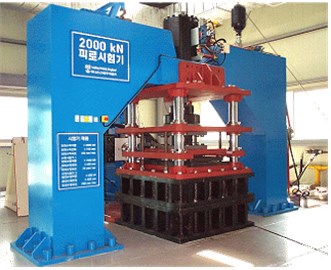
Fig. 5Creep experiment
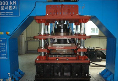
The creep test is performed to determine the deformation of a laminated rubber bearing under constant long term compression without shear train. The creep was measured at 10 more points of specimen during three cases of periods such as 100 hr to 101 hr, 101 hr to 102 hr and 102 hr to 103 hr.
Specimen No. 1 was tested under 23 °C temperature conditions, and the other two specimens were tested under a constant temperature of 23±2 °C to determine the long term deformation of a laminated rubber bearing versus temperature. The vertical displacement of the specimen was measured by installing two highly sensitive displacement devices and the vertical displacement was determined by the mean of two measured values. The test conditions are shown in Fig. 5. The vertical load was a compressive stress applied for 1 min. The compression force loads applied to the specimens were as follows: Nos. 1, 2, and 3 were 370 kN each, No. 4 was 580 kN, and No. 5 was 450 kN. The deviation of the compressive load was less than 3 %.
4. Test specimens
Fig. 6 shows the change in vertical displacement immediately after applying the compressive load during the temperature change condition. This vertical displacement is the relative displacement with respect to the vertical displacement against the LRB, and would decrease with expansion of the laminated rubber.
Specimen No. 1 was tested at 23 °C. Under the temperature changing condition, it is necessary to convert the temperature to compare the displacement of specimen No. 1 with another specimen that was tested under a constant temperature of 23±2 °C [19]. The relation of vertical displacement at 23 °C with is the change in the vertical displacement at °C are as follows:
where means the change in the vertical displacement at 23 °C, and is the change in the vertical displacement at °C. is the surface temperature (°C) of the test specimen, and is the coefficient of linear thermal expansion (23 °C at °C).
The coefficient of thermal expansion of specimen No. 1 at each time interval is given in Table 3. The creep deformation rate is calculated as follows:
The coefficients and of the functional equation given by Eq. (4) can be calculated by the creep deformation of specimen Nos. 2 to 5 (with test temperatures constantly maintained at 23±2 °C. The result is substituted into Eq. (5) [20]. Here, is the percentage of total rubber thickness with respect to the creep amount after decades of use, and is the time in hours:
Table 3Thermal coefficient α (mm / °C)
Time | 1 to 100 hr | 101 to 1000 hr |
Linear gradient | –0.000371094 | –0.000329716 |
We measured the vertical displacement with a loading design compressive load for 1000 hr under different conditions using three types of laminated rubber bearings. The test results show that specimen No. 1 tested at air temperature has 2.7 times and 3.9 times the vertical deformation of specimen Nos. 2 and 3, respectively, when tested under constant temperature. No. 3 (the high damping rubber bearing) had the smallest vertical deformation. Fig. 6 shows the test results for each specimen for 1000 hr.
Fig. 6Changes in vertical deformation versus time
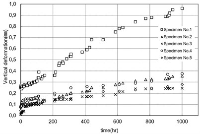
Fig. 7 shows the change in vertical displacement versus test temperature after applying the design compressive load. Specimen No. 1 was tested under °C and shows a sharp increase in vertical deformation as the temperature decreased. On the other hand, specimen No. 2 was tested under a constant temperature of 23±2 °C and shows a relatively stable and gradual increase in vertical deformation. The vertical displacement also shows repeated compression and expansion of the rubber with temperature changes. Fig. 8 shows the vertical deformation versus temperature change. The lower the temperature, the higher the vertical displacement, and with higher temperature, the vertical displacement decreases. Figs. 9 and 10 show the mutual relationship between the shear modulus () and primary shape factor (). If the section property and the shape factor are the same, an increase in shear modulus produces an increase in the amount of creep. Also, with an increase in the primary shape factor (), the vertical rigidity increases and the creep amount decreases. Specimen No. 4 in Fig. 10 has a lead plug in the central laminated rubber. In this case, the creep amount and the shape factor () increaseafter 100 hrs. Compared with the same size specimen (No. 5), the axis compressive stress is large, but the area receiving compressive load decreases due to the lead plug inside. Thus, its vertical deformation increases after a certain amount of time.
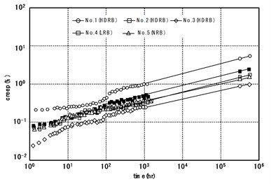
Table 4 shows a semi-logarthmic time axis of creep after 60 and 100 years of use according to Eq. (5). We estimated that the amount of creep in a high damping rubber bearing (Nos. 1, 2, and 3) under compressive stress of 7.5 MPa after 100 yr to be 0.56 to 2.92 mm. We also estimated that the lead rubber bearing (No. 4) creep amount is 1.16 mm and the compressive stress rubber bearing is 1.08 mm. According to Oh et al., rubber creep visually occurs as many years pass, it decreases as the primary shape factor () increases, and it depends on the value of regardless of the axis stress. If this is correct, the creep test on the laminated rubber bearing should be performed over a much longer period, and should be studied through long term creep test by converting shape factor. Table 4 shows the creep data and its rate of change after 60 yrs and 100 yrs of use by using vertical displacement data of the laminated rubber bearing after a loading design compression load was applied for 1000 hrs. The long-term creep estimate was calculated as the semi-logarithmic according to Eqs. (4) and (5), as shown in Fig. 11.
Fig. 7Relationship between vertical deformation and temperature
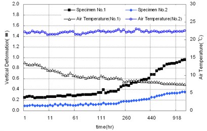
Fig. 8Relationship between vertical deformation and temperature for fluctuation of the compressive load
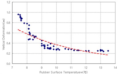
Fig. 9Effect of shear modulus (G)
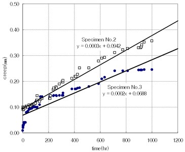
Fig. 10Effect of primary shape factor (S1)
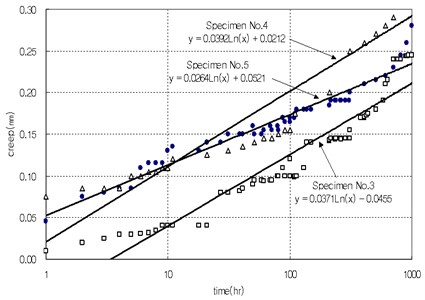
Table 4Estimated creep value (mm)
Specimen | 1000 hrs | 60 yrs after | 100 yrs after | Condition | ||
HDRB | No. 1 | Creep (mm) | 0.96 | 2.77 | 2.92 | Air temperature |
Strain ratio (%) | 1.92 | 5.54 | 5.84 | |||
No. 2 | Creep (mm) | 0.36 | 1.54 | 1.62 | Laboratory temperature (23±2 °C) | |
Strain ratio (%) | 0.72 | 3.08 | 3.24 | |||
No. 3 | Creep (mm) | 0.24 | 0.54 | 0.56 | ||
Strain ratio (%) | 0.48 | 1.08 | 1.12 | |||
LRB | No. 4 | Creep (mm) | 0.38 | 0.98 | 1.03 | |
Strain ratio (%) | 0.44 | 1.12 | 1.18 | |||
NRB | No. 5 | Creep(mm) | 0.28 | 1.02 | 1.08 | |
Strain ratio (%) | 0.3 | 1.10 | 1.16 | |||
HDRB test specimens No. 1, 2, and 3 are expected to deform by 0.54, 1.54, and 2.77 mm, respectively, after 60 yrs of use under the design compression stress condition. The deformation rate of each test specimen is expected to deform from a minimum of 1.08 % to a maximum of 5.54 % after 60 yrs of use. Here, the creep deformation rate was calculated by dividing the estimated creep data that was based on the test results by the total thickness of the rubber layers.
Fig. 12Comparison of creep (mm)
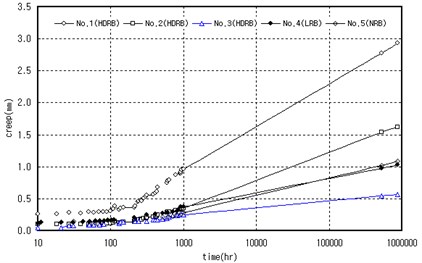
Fig. 13Comparison of creep rate (%)
5. Conclusions
We performed creep tests in order to determine the creep deformation characteristics of an LRB, HDRB, and LRB, and NRB manufactured based on seismic isolation design that is not usually considered at the design stage. The creep tests were performed for 1000 hr on three types of laminated rubber bearing: three specimens used high damping rubber, one specimen had lead inside the laminated rubber, and one specimen was made of regular rubber. After the test, we analyzed the measurement data and creep changes according to factors such as temperature changes and the shear modulus. We then estimated the rate of change of creep deformation after 60 years of common use. Our test results are summarized as follows:
1) The analysis of the relationship between creep vertical deformation and temperature based on the laminated rubber bearing test results at 23 °C and 23±2 shows that a higher temperature results in a lower chance of creep deformation, and a lower temperature increases the chance of creep deformation.
2) On the condition that the size and the shape factor of shape are same, then a larger shear modulus results in an increase in creep. Also, as the primary shape factor () increases, the vertical rigidity increases and the creep amount decreases.
3) The creep deformation calculation for three types of laminated rubber bearing under compressive load for 1000 hours shows that the deformation after 60 years is 0.56 to 2.92 mm.
4) The laminated rubber bearing used in this research was exposed to outside environmental changeable factors such as oxidation in the air, and ozone for longer period than usual period of use on the bridge system. In this regard, a long term creep test which considers outside environmental factors that could influence creep deformation should be performed.
References
-
Itoh Yoshito, Gu Haosheng, Satoh Kazuya, Yamamoto Yoshihisa Long-term deterioration of high damping rubber bridge bearing. Doboku Gakkai Ronbunshuu A, Vol. 62, Issue 3, 2006, p. 595-607.
-
Stevenson A. Longevity of natural rubber in structural bearing. Plastics Rubber Proceeding and Applications, Vol. 5, Issue 3, 1985.
-
Yamamoto Sachie, Kikuchi Masaru, Ueda Masaiki, Aiken Ian D. A mechanical model for elastomeric seismic isolation bearings including the influence of axial load. Earthquake Engineering and Structural Dynamics, Vol. 38, Issue 2, 2009, p. 157-180.
-
Ju Oh, Nok Park Kun, Hyun Cho, Jong Yun Lee Prediction about the deflection of laminate rubber bearing due to long-term creep test. Korean Society of Civil Engineering Conference and Civil Expo, 2007, p. 2488-2491.
-
Sae-oui P., Sirisinha C., Hatthapanit K. Effect of blend ratio on aging, oil and ozone resistance of silica-filled chloroprene rubber/natural rubber (CR/NR) blends. eXPRESS Polymer Letters, Vol. 1, Issue 1, 2007, p. 8-14.
-
Yura J., Kumar A., Yakut A., Topkaya C., Becker E., Colligwood J. Elastomeric Bridge Bearings: Recommended Test Methods. NCHRP Report 449, 2001, p. 42-50.
-
Derham C. J., Waller R. A. Long-term tests confirm laboratory predictions. Rubber Development, Vol. 28, Issue 1, 1975, p. 7-11.
-
Ju Oh, Young Park Jin, Nok Park Kun, Dong Kim See, Kyu Park Sung An experimental study of the long-term creep characteristic of high damping rubber bearings. Journal of the Earthquake Engineering Society of Korea, Vol. 13, Issue 1, 2009, p. 53-60.
-
Kunde M. C., Jangid R. S. Seismic behavior of isolated bridges: a-state-of-the-art review. Electronic Journal of Structural Engineering, Vol. 3, 2003, p. 140-170.
-
de Raaf Michael G. P., Tait Michael J., Toopchi-Nezhad Hamid Stability of fiber-reinforced elastomeric bearings in an unbonded application. Journal of Composite Materials, Vol. 45, Issue 18, 2011, p. 1873-1884.
-
Kumar Manish, Whittaker Andrew S., Constantinou Michael C. Experimental investigation of cavitation in elastomeric seismic isolation bearings. Engineering Structures, Vol. 101, 2015, p. 290-305.
-
Young Chung Gil, Ho Ha Dong, Nok Park Kun, Oh Kwon Hyung Experimental study on characteristics of low hardness rubber bearing. Journal of the Earthquake Engineering Society of Korea, Vol. 6, Issue 4, 2002, p. 39-49.
-
ISO 22762-1. Elastomeric Seismic Protection Isolation. Part 1: Test Methods. 2010.
-
Manos G. C., Sextos A., Mitoulis S., Kourtides V., Geraki M. Tests and improvements of bridge elastomeric bearings and software development for their preliminary design. The 14th World Conference on Earthquake Engineering, 2008.
-
ISO 22762-2. Elastomeric Seismic Protection Isolation. Part 2: Applications for Bridges. 2010.
-
Yoon Hyejin, Cho Changbeck, Kim Youngjin, Kwahk Imjong A experimental study on the stiffness characteristics of elastomeric bearings. Journal of the Korean Society of Civil Engineers, Vol. 28, Issue 4A, 2008, p. 475-485.
-
ISO 22762-3. Elastomeric Seismic Protection Isolation. Part 3: Applications for Buildings. 2010.
-
Choun Young-Sun, Park Junhee, Choi In-Kil Effects of mechanical property variability in lead rubber bearings on the response of seismic isolation system for different ground motions. Nuclear Engineering and Technology, Vol. 46, Issue 5, 2014, p. 605-618.
-
Tae Hwang Kee, Won Seo Dae, Gook Cho Sung Prediction of long term performance and creep of laminated natural rubber bearings (NRB). Journal of the Earthquake Engineering Society of Korea, Vol. 17, Issue 3, 2013, p. 117-125.
-
Woon Choi Se, Joon Lim Hong, Jin Cho Hyun, Nok Park Kun, Ju Oh, Young Jung Hie Evaluation of factors influencing the dynamic characteristics of low hardness high damping rubber bearings. Journal of the Earthquake Engineering Society of Korea, Vol. 12, Issue 3, 2008, p. 11-20.
Cited by
About this article

This research was supported by Yeungnam University Research Grant in 2016.
