Abstract
This article examines the efficiency of gas condensate heaters in the context of reducing the operating costs of combined-cycle gas installations. Gas condensate heaters are an innovative technological solution aimed at restoring the heat released during steam condensation. Based on the principles of returning part of the heat back to the system, their use contributes to a significant reduction in fuel consumption, which, in turn, leads to a reduction in operating costs. The work examines the mechanisms of operation of gas condensate heaters, their thermal characteristics, as well as their impact on the overall energy efficiency of combined-cycle gas installations. Using the example of the oil refining industry, the practical application of this technology for optimizing thermal processes is demonstrated. In conclusion, the importance of gas condensate heaters in the context of building environmentally sustainable and energy-efficient production systems is emphasized.
1. Introduction
In modern industrial settings, efficient energy use is crucial for optimizing the performance of combined heat and power (CHP) plants, focusing on reducing fuel consumption costs through innovative technology. Condensate gas heaters are seen as a promising solution for improving energy efficiency in CHP systems. This article evaluates the effectiveness of condensate gas heaters in cutting operational costs, highlighting their role in energy-efficient and environmentally friendly technology. It also explains the unique function of waste heat boilers in steam power plants, which lack air preheaters and use condensate gas heaters to prevent low-temperature corrosion by maintaining the condensate temperature at the inlet to the heater at 55-60 °C [1, 2]. Recirculation of preheated condensate is a common practice to achieve this temperature, and in district heating CHPs, an additional heat exchanger is used to heat network water at 100-120 °C.
2. Materials and methods
The total electricity consumption for internal needs of the combined heat and power plant the sum of electricity expenditures for the internal needs of the gas turbine, waste heat boiler, steam turbine, district heating installation, and additional electricity consumption associated with heat release in the form of steam:
The electricity expenditures for the internal needs of the waste heat boiler include costs for actuator operation and electric pumps. To improve the efficiency of the power block, the focus is on reducing electricity expenditures for the internal needs of the waste heat boiler, such as eliminating energy-intensive elements or reducing electricity costs for electric drives. One such element is the condensate recirculation pump (CRP), which transfers heated condensate to the inlet of the condensate gas heater (CGH) to maintain the condensate temperature above 55-60 °C and prevent low-temperature corrosion. Additionally, a water-to-water heat exchanger is installed on the recirculation line to heat network water, as demonstrated in [4-7]. The electricity costs for operating the CRP depend on the amount of pumped liquid [8]. The condensate flow through the recirculation line is determined by the energy balances of the CGH thermal scheme. Known methods to increase the efficiency of CHP power blocks do not allow for eliminating the installation of the CRP in the CGH technological scheme. These methods focus on reducing the proportion of hot condensate pumped into the CGH.
The method for investigation in this work is to develop a technological scheme for incorporating CGH heating surfaces without a recirculation line, with the main criterion being the elimination of low-temperature corrosion. The proposed CGH scheme should fully correspond to the traditional CGH scheme (with recirculation) in terms of technological characteristics. To develop a technological scheme for the CGH without condensate recirculation and study the operating modes of the CGH under such a scheme, the author decided to use as a basis a CHP unit, representing a two-shaft monoblock consisting of a gas turbine, waste heat boiler, and steam turbine. It is necessary to establish the variability of the proposed scheme for power blocks of different capacities and identify the dependencies of the relative heat acceptance of stages on parameters known at the initial design moment. Since the waste heat boiler is a complex system of heat exchangers, designing the CGH based on a stepped condensate heating scheme and studying the operating modes of such a scheme should be done in conjunction with designing the waste heat boiler.
2.1. Condensate gas heater description
The condensate gas heater (CGH) is a gas-to-water recuperative heat exchanger configured in a counter flow scheme. To maintain the condensate temperature at the inlet of the CGH within recommended limits (55-60°C), a recirculation system is employed. The operation principle of the recirculation system involves extracting the required amount of preheated condensate at the outlet of the CGH and feeding it back to the inlet of the CGH. Additionally, a water-to-water heat exchanger (WWHE) is installed on the recirculation line, designed for heating network water.
2.2. Development of the stepped condensate heating scheme
One way to enhance the efficiency of thermal power plants (TPPs) is by reducing electricity expenditures for internal needs, particularly in the waste heat boiler (WHB) of a combined heat and power (CHP) plant, as highlighted in [9]. The condensate recirculation pump (CRP) is identified as the primary electricity consumer in the WHB scheme, tasked with maintaining the condensate temperature at the CGH inlet at 55-60 °C [1, 2, 10]. Verification calculations were conducted to determine the electricity consumption of the CRP and the condensate electric pump (CEP), focusing on the load dependence on the condensate temperature downstream of the steam turbine condenser, with results summarized in Table 1.
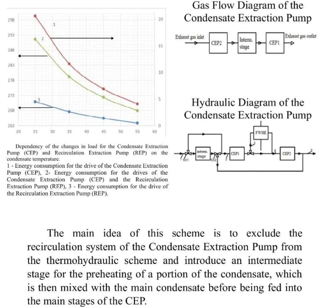
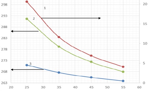
The following are graphical dependencies of the power of the condensate recirculation pump (CRP) and the power of the condensate electric pump (CEP) on the condensate temperature downstream of the steam turbine condenser (Fig. 1). The plots are constructed based on the data provided in Table 1.
The graph indicates that the maximum energy consumption for the condensate recirculation pump (CRP) and the condensate electric pump (CEP) is achieved at the lowest condensate temperature (25 °C). This is explained by the fact that a larger amount of thermal energy is required to heat the condensate before feeding it into the heating surface, leading to an increase in the total condensate flow through the CGH heating surface, which is the sum of condensate flows for the waste heat boiler (WHB) and recirculation. As mentioned earlier, one of the ways to reduce energy costs for internal needs is to develop a technological scheme for a low-temperature heating surface of the WHB, excluding the condensate recirculation system.
Table 1Main results of the waste heat boiler calculations
Title | Unit of measurement | Inlet condensate temperature (ICT) | |||
25 | 35 | 45 | 55 | ||
Condensate flow for boiler makeup | t/h | 277,7 | 277,7 | 277,7 | 277,7 |
Condensate inlet pressure of the condensate gas heater | MPa | 2,7 | 2,66 | 2,63 | 2,6 |
Condensate outlet pressure from the condensate gas heater | MPа | 2,5 | 2,5 | 2,5 | 2,5 |
Condensate outlet temperature from the condensate gas heater | °C | 155 | 155 | 155 | 155 |
Calculated power of the electric drive for the condensate electric pump | kW | 271 | 267,6 | 265,45 | 263,85 |
Calculated power of the electric drive for the condensate recirculation pump | kW | 20,6 | 11,6 | 6,9 | 4,1 |
Total calculated power of the electric drives | kW | 291,6 | 279,2 | 272,35 | 267,95 |
Fig. 1Dependency of the changes in load for the Condensate Extraction Pump (CEP) and Recirculation Extraction Pump (REP) on the condensate temperature: 1 – energy consumption for the drive of the Condensate Extraction Pump (CEP), 2 – energy consumption for the drives of the Condensate Extraction Pump (CEP) and the Recirculation Extraction Pump (REP), 3 – energy consumption for the drive of the Recirculation Extraction Pump (REP)
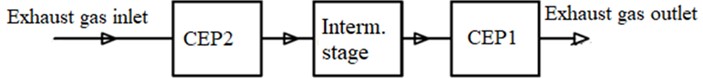
During the work, a series of technological scheme solutions were developed, and an option for the technological scheme of the condensate gas heater (CGH) was selected that aligns with the previously stated research goals. The alternative nature of the proposed CGH technological scheme lies in the exclusion of the condensate recirculation system from the CGH circuit. The hydraulic scheme and the gas circuit scheme of the CGH are presented in Fig. 2 and 3, respectively.
Fig. 2Hydraulic diagram of the condensate extraction pump (CEP)
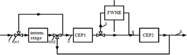
Fig. 3Gas flow diagram of the condensate extraction pump (CEP)
The main idea of this scheme is to exclude the recirculation system of the Condensate Extraction Pump (CEP) from the thermohydraulic scheme and introduce an intermediate stage for the preheating of a portion of the condensate, which is then mixed with the main condensate before being fed into the main stages of the CEP. To achieve this, the entire heating surface of the CEP is divided into three stages:
1) Inlet condensate stage – CEP1.
2 Intermediate stage for condensate preheating – Interm. Stage.
3) Outlet condensate stage – CEP2.
The movement of the working fluid (condensate) in the CEP system occurs as follows. Cold condensate enters the inlet stage (CEP1), and in parallel with the inlet pipeline, the intermediate stage (Interm. Stage) is included, where the condensate is preheated. The thermal load of the intermediate stage is equal to the amount of energy required to preheat the entire condensate before feeding it into CEP1 to a temperature not lower than 60 °C. Regulation of the condensate flow through the intermediate stage, and accordingly, the thermal load of this stage, is carried out by installing a three-way valve at the inlet (Valve1). The preheated condensate with a temperature of 60 °C then enters CEP1.
The heated condensate from CEP1 goes to the feedwater-water heat exchanger (FWHE) to warm the network water, then to CEP2 for final heating before entering the deaerator. Traditional CEP schemes use a bypass line with cold condensate to maintain subcooling to boiling. In the proposed scheme, partially preheated condensate is used for bypassing, which is effective when the condensate temperature after the steam turbine condenser is around 60 °C or higher, eliminating the need for additional heating.
Operating the intermediate stage in a zero-flow mode can disrupt the hydrodynamic regime and potentially damage the heating surface. To regulate the condensate flow and maintain subcooling before the deaerator, a three-way valve (Valve2) is installed after the intermediate stage. The inclusion of the intermediate stage required refinement, especially for bypassing the preheated condensate.
Fig. 4Diagram of the intermediate stage: 1 – downward flow of the medium, 2 – upward flow of the medium
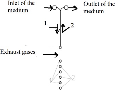
Traditionally, waste-heat boilers use a counterflow scheme for heating surfaces. Including the intermediate stage in this scheme would increase the condensate flow to maintain subcooling at the deaerator inlet, leading to a higher thermal load on the intermediate stage and reduced heat for CEP1, affecting the FWHE's thermal load. Therefore, the intermediate stage was divided into two parts (inlet and outlet) within one section, consisting of one row of tubes along the gas flow. The basic schematic of the intermediate stage is shown in Fig. 4. For initial analysis, the tube diameter of the intermediate stage was assumed to be equal to that of the main stages (CEP1 and CEP2).
At the conclusion of the preliminary elaboration of the technological scheme of the Condensate Extraction Pump (CEP) without condensate recirculation, a thermohydraulic calculation of the waste-heat boiler utilizing this scheme was carried out. The main calculation results for the CEP system are summarized in Table 2.
Table 2Key calculation results of the condensate extraction pump (CEP) system using the staged condensate heating scheme
Title | Unit of measurement | CEP2 | Interm. stage | CEP1 |
Parameters of the heating medium | ||||
Heat absorbed from gases according to the balance | kW | 26185,96 | 11198,68 | 18285,96 |
Inlet gas temperature | °C | 194 | 148 | 128 |
Outlet gas temperature | °C | 148 | 128 | 96 |
Parameters of the heated heat transfer medium | ||||
Flow rate of the medium | t/h | 277,67 | 146,08 | 277,67 |
Inlet gas temperature | °C | 75 | 25 | 60 |
Outlet gas temperature | °C | 155 | 91 | 116 |
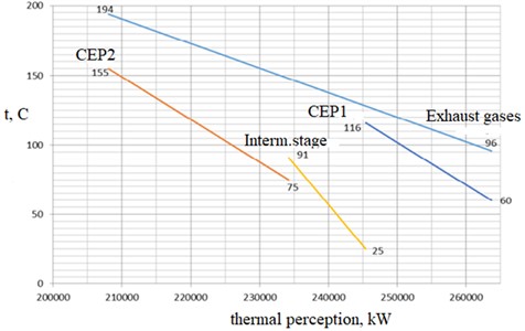
Based on the results of the thermohydraulic calculations of the waste-heat boiler utilizing the Condensate Extraction Pump (CEP) system without condensate recirculation, a Q-t diagram has been constructed and is presented in Fig. 5 (only the CEP system is shown on the diagram).
Fig. 5Q-T diagram of the condensate extraction pump (CEP) system
3. Conclusions
In conclusion of the article dedicated to the efficiency of condensate gas heaters in the context of reducing operational costs of steam and gas installations, key findings are summarized, and prospects for further research are outlined.
Based on the data and practical results of applying condensate gas heaters in the industry, it can be asserted that these technological devices are an effective means of optimizing energy processes. The return of heat released during steam condensation back into the system demonstrates the potential for significant fuel consumption reduction, thereby contributing to lower operational costs and improved energy efficiency.
An important aspect of the research is the consideration of practical examples of implementing condensate gas heaters in the industry. This not only confirms the theoretical efficiency of this technology but also its successful application in real production conditions.
However, despite the positive results, this field requires further research aimed at a more in-depth study of the mechanisms of operation of condensate gas heaters, optimizing their design, and regulating their operation depending on changing production conditions.
In summary, it can be concluded that condensate gas heaters represent a promising solution for improving the energy efficiency of steam and gas installations, coupled with a significant reduction in operational costs and enhanced production stability. This article makes a significant contribution to the field of energy optimization and can serve as a basis for subsequent technological innovations and developments in this direction.
References
-
Tsanev, S. V., Burov, V. D., Remezov, and A. N., Gas Turbine and Steam-Gas Plants of Thermal Power Stations. Moscow: MEI Publishing House, 2002.
-
E. Guillaume, “Study of the thermal schemes of CCPP with the selection of optimal operating modes for the conditions of cote d’Ivoire,” Moscow, 2014.
-
“On approval of the procedure for determining the norms of specific fuel consumption to produce electrical and thermal energy: Order No. 580,” Ministry of Energy of the Republic of Kazakhstan, 2016.
-
Budakov, I. V., Burov, and V. D., “Determination of the dew point behind the boiler-utilizer with the aim of optimizing the temperature of the outgoing gases,” New in Russian Power Engineering, Electronic Journal, Vol. 11, pp. 35–45, 2011.
-
I. V. Budakov, “Study and improvement of the operation modes of the CCPP-325,” Moscow, 2012.
-
B. S. Leznov, Energy Saving and Adjustable Drive-in Pump Installations. Moscow: Yagorba, 1998.
-
Sitas, V. I., Pyoshk A., Fatkullin, and R. M., “The use of adjustable fluid couplings to reduce the consumption of electricity for the needs of power plants,” Electric Stations, Vol. 2, pp. 61–65, 2003.
-
V. N. Yurenev and P. D. Lebedev, Heat Engineering Handbook. Moscow: Energiya, 1975.
-
Khutornenko, S. N., Fursov, I. D., Zhukov, and E. B., “Identification of the main groups of factors that affect the increase in the efficiency of power units of the PGU by reducing the consumption of electricity for their own needs to ensure the operation of the boiler-utilizer,” in Power Engineering: Efficiency, Reliability, Safety, 2015.
-
Burov et al., Thermal Power Plants: A Textbook for Universities. Moscow: MEI Publishing House, 2009.
About this article

The authors have not disclosed any funding.
The datasets generated during and/or analyzed during the current study are available from the corresponding author on reasonable request.
The authors declare that they have no conflict of interest.
