Abstract
The auxiliary power supply unit for railway vehicles delivers various power to the passenger car. Maintaining isolation between the catenary power line and the auxiliary power in the compartment is typically essential. To ensure electrical isolation, an efficient LLC resonant converter is utilized among isolated DC-DC converters. Generally, LLC resonant converter primarily employ PFM control method. However, there is a limitation in increasing the switching frequency at high input voltages, making it difficult to handle wide input voltage fluctuations from the overhead catenary power line. To overcome this limitation, the PFM control method is introduced alongside the existing PFM control method, resulting in the presence of two controllers. However, since these two controllers regulate the output voltage differently, there is a potential for output voltage overshoot due to significant input voltage fluctuations. This paper proposes a method that combines PFM and PWM controllers, along with feed-forward compensation, to address these issues. The effectiveness of this proposed method is validated through PSIM simulation and experimentation.
1. Introduction
The Auxiliary Power Unit (APU) for railway vehicles generates three-phase AC voltage using the DC voltage supplied from the catenary, supplying power to various onboard systems such as air conditioning and lighting. Therefore, the APU, being closely related to passengers, requires electrical insulation. [1]-[3]. This insulation is achieved using an LLC resonant converter, which achieves high efficiency through zero-voltage switching in the entire load range using a transformer-based insulation DC-DC converter. However, due to the nature of APUs using a wide voltage range from the catenary as a power source, LLC resonant converters have the drawback of requiring a wide variation in switching frequency to accommodate this, leading to increased control complexity.
Fig. 1(a) depicts the configuration of a conventional railway vehicle APU, which combines a Boost converter and an LLC converter. The Boost converter is configured at the input of the LLC converter to overcome the mentioned weakness of the LLC converter and accommodate the varying input voltage. The LLC converter operates at the resonant frequency, such as the switching frequency, always maintaining a voltage gain of 1. However, this two-stage power conversion system increases volume and reduces overall power conversion efficiency [4].
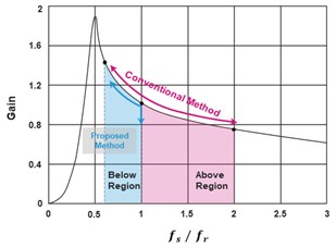
Therefore, research is underway to overcome these drawbacks by applying a three-level LLC converter with modulation control, as shown in Fig. 1(b). This three-level LLC converter, as depicted in Fig. 2 boosts the output voltage through frequency control in the region where the input voltage exceeds the rated value and boosts the voltage through modulation control in the region where the input voltage is lower than the rated value [5].
The three-level LLC converter with frequency and modulation control overcomes the drawbacks of the two-stage power conversion system. However, due to the different methods of controlling the output voltage depending on the input voltage, the performance of excessive responses such as overshoot and undershoot in the output voltage is not satisfactory, leading to reliability issues. Therefore, this paper proposes a feedforward compensation method and a hybrid approach of combining frequency and modulation controllers to ensure stability and reliability while accommodating a wide input voltage range.
Fig. 1Auxiliary power unit system
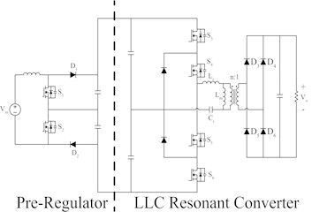
a) Existing auxiliary power unit (Two-Stage)
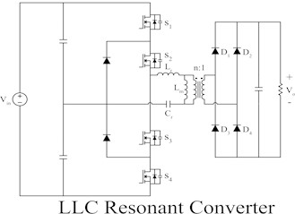
b) Auxiliary power unit system with 3-level LLC converter (Single-Stage)
Fig. 2LLC resonant converter voltage gain graph and frequency modulation range
2. 3-level LLC resonant converter
2.1. Operation principle of duty control in a 3-level LLC resonant converter
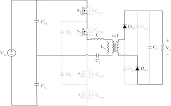
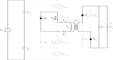
Fig. 3 illustrates the conduction states of the system with duty control applied in each mode. Since the system can be divided into a total of 8 modes, describing 4 modes within one half-cycle due to symmetry [6-7].
Mode 1 begins after both capacitors and in Fig. 3 are fully charged, achieving the ZVS condition for and . The resonant tank voltage receives half of the total input voltage. At this point, the inductor and capacitor start resonating, and the differential component between and is transferred to the secondary side of the transformer. As a result, the secondary side rectifier diode and conduct, delivering the output voltage to the secondary side of the transformer. Subsequently, at the pulse width modulation control command time , is turned off simultaneously, marking the end of mode 1.
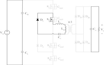
The duration of mode 1 allows for the control of the average voltage input to the resonant tank. After turned off in mode 1, mode 2 is entered. During this transition, although the input voltage of the resonant tank decreases to 0V, the current is and still exist, maintaining the voltage across the secondary side rectifier didoes and , and thus, the voltage across the secondary side of the transformer remains . Subsequently, mode 2 concludes when and become equal.
Fig. 3Conduction state of each mode
a) Mode 1
b) Mode 2
c) Mode 3
d) Mode 4
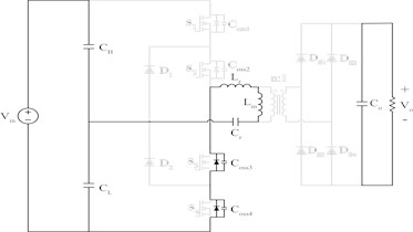
Mode 3 is the interval where the resonant current transfers all its energy to the secondary side and reaches the same value as . During this phase, and are conducting, allows the circulating current to flow within the resonant tank.
Mode 4 is the dead time interval implemented to achieve ZVS. When which was conducting, is turned off, the energy of the magnetizing inductance charges the output capacitances and , achieving the ZVS turn on condition for the next cycle.
3. Voltage controller design of 3-level LLC resonant converter
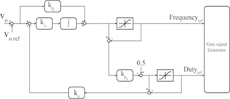
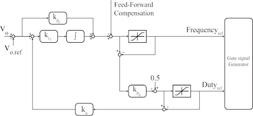
In this chapter, a voltage controller utilizing frequency and duty cycle modulation to accommodate input voltage fluctuations is designed. Fig. 4 represents the block diagram of the proposed controller, outlining its structure. The operation of the controller involves frequency control when the input voltage is equal to or lower than the rated voltage, and duty cycle control when it exceeds the rated voltage. Frequency control adjusts the frequency according to the output voltage within the limiter range of the frequency controller through a PI controller, while the duty cycle is maximized to generate the signal. On the other hand, duty cycle control calculates the duty cycle based on the error between the PI output of the frequency controller and the limiter output through a P controller and a limiter, with the frequency fixed at its maximum value to output the signal. However, a drawback exists where excessive states occur in the output voltage during fluctuations in the input voltage in the varying region, although the output follows the desired voltage [8]-[10].
Fig. 4Block diagram of the proposed hybrid (PFM, PWM) controller
Excessive states such as overshoot and undershoot in the output voltage during input voltage fluctuations can be improved through feedforward compensation. The controller with this added feedforward compensation is represented in a structure similar to Fig. 5. The feedforward compensator can be designed based on voltage gain curves associated with the goodness factor and inductance ratio. Additionally, since the controller operates based on frequency, the design of feedforward compensation is based on frequency and input voltage. Feedforward compensation is utilized within the controller to swiftly respond to input voltage variations, thus, instead of employing complex voltage gain curve equations, it is linearly approximated for use.
Fig. 5Block diagram of the controller with the proposed feed-forward compensation
4. Simulation
The proposed controller is verified through simulation and experiment using PSIM. Table 1 shows the specifications applied to both simulation and experiment. The simulation should ideally cover the input voltage of a maximum of 1800 V and a minimum of 900 V at a rated of 1500 V, but due to the difficulty of further experimental verification, the output voltage was lowered to about 1/3 of the actual output voltage of 700V for verification. Fig. 6 shows the simulation results.
Table 1Simulation parameter of 3-level LLC resonant converter
Parameter | Value | Unit |
Output Power | 1 | kW |
Input voltage | 300-550 | V |
Output voltage | 200 | V |
Resonant frequency | 100 | kHz |
Table 2Comparison analysis of transient status according to the presence or absence of feed-forward compensation
Comparison target | Overshoot peak | Undershoot peak | Unit |
Absence of feed-forward compensation | 15 | –15 | V |
Presence of feed-forward compensation | 3 | 0 | V |
In Region 1, an input voltage of 370 V is applied to control the output voltage through frequency modulation. In Region 2, the input voltage is boosted to 550 V to control the output voltage through a fixed frequency and a modulated duty cycle. Region 3 includes the process of switching control mode through frequency modulation control by increasing the input voltage to 300V and controlling the output voltage with a modulated frequency and a fixed duty cycle. Therefore, in Section1 to 3, a change in the operating point according to the change in the input voltage was observed, so that the modulation ratio and frequency change could be confirmed.
Fig. 6(a) shows the waveform to which the feedforward compensation is not applied, and (b) shows the waveform to which the feedforward compensation is applied. In (a), when the input voltage fluctuates, an overshoot and an undershoot occur in the output voltage. Therefore, in (b), it can be seen that by providing feedforward compensation for the input voltage, the overshoot and undershoot are greatly reduced in the output voltage. The results are shown in Table 2. When the overshoot input voltage increases, the overshoot decreased from 7.5 % to 1. 5%, and the undershoot decreased from 7.5 % to 0 %. These results can improve the transient problem occurring in the hybrid controller during feedforward compensation.
Fig. 6Simulation results
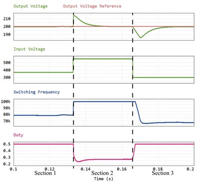
a) Waveform without feed-forward compensation
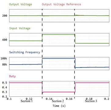
b) Waveform with feed-forward compensation
5. Conclusions
In this paper, a control strategy combining frequency control and duty control techniques is designed for a 3-level LLC resonant converter to improve the transient state occurring during input voltage variations, applying feedforward compensation to ensure stable output. Auxiliary power unit for railway vehicles have the characteristics of rapid input voltage fluctuations due to the impact of the pantograph graph connected to the catenary. As a result, research is actively underway on single-stage structures without pre-regulator power supplies to address the drawbacks of double-stage structures with significant switching losses and space requirements. However, removing the pre-regulator power supply exposes the resonant converter directly to a wide range of input voltages. Therefore, a control technique is proposed that combines frequency control and duty ratio control to design the controller and improve the transient state occurring during rapid input voltage fluctuations, thereby controlling the voltage. The proposed control technique is verified through simulation to demonstrate its ability to track voltage commands even during input voltage variations and to control without transient states during rapid input voltage fluctuations.
References
-
G. Bolton, “Auxiliary power systems for rolling stock,” IET Professional Development Course on Electric Traction Systems, 2010.
-
Y. Haroen, P. A. Dahono, and J. Sutanto, “A new type of DC-DC converter for rolling stock auxiliary power supply,” in International Conference on Power Electronic Drives and Energy Systems for Industrial Growth, 1998.
-
J.-C. Kim, S.-G. Baek, and H. Cha, “Auxiliary power unit control algorithm for input voltage disturbance suppression,” The Transactions of The Korean Institute of Electrical Engineers, Vol. 64, No. 12, pp. 1810–1817, 2015.
-
J.-B. Lee and I.-H. Cho, “Research on power converters for high-efficient and light-weight auxiliary power supplies (APS) in railway system,” Journal of the Korean Society for Railway, Vol. 20, No. 3, pp. 329–338, Jun. 2017, https://doi.org/10.7782/jksr.2017.20.3.329
-
M.-J. Kim, S.-W. Baek, H.-W. Kim, J.-H. Choi, and J.-W. Kang, “Loss analysis of 3-level LLC converter with duty control,” in 5th International Conference on Power Engineering and Renewable Energy (ICPERE), 2022.
-
S. W. Baek, H. W. Kim, and J. W. Kang, “Auxiliary power unit for railway vehicles using three-level LLC converter with pulse width modulation control,” in International Symposium on Electrical and Electronics Engineering (ISEE), 2019.
-
Zong et al., “Asymmetrical duty cycle-controlled LLC resonant converter with equivalent switching frequency doubler,” IEEE Transactions on Power Electronics, Vol. 31, No. 7, pp. 4963–4973, 2015.
-
Wang et al., “Modeling and analysis of a current-fed ZCS full-bridge DC/DC converter with adaptive soft-switching energy.,” in 24th Annual IEEE Applied Power Electronics Conference and Exposition, 2009.
-
Deblecker, O., A. Moretti, and F. Vallee, “Comparative analysis of two zero-current switching isolated dc-dc converters for auxiliary railway supply.,” in International Symposium on Power Electronics, Electrical Drives, Automation and Motion, 2008.
-
B. Cheng, F. Musavi, and W. G. Dunford, “Novel small signal modeling and control of an LLC resonant converter,” in 2014 IEEE Applied Power Electronics Conference and Exposition – APEC 2014, pp. 2828–2834, Mar. 2014, https://doi.org/10.1109/apec.2014.6803705
About this article

The authors have not disclosed any funding.
The datasets generated during and/or analyzed during the current study are available from the corresponding author on reasonable request.
The authors declare that they have no conflict of interest.
