Abstract
To solve the problem of noise interference, it is difficult to extract multi-scale information from complex vibration signals in fault diagnosis with the single-scale convolution kernel of classical deep learning model convolutional neural network (CNN). Therefore, a fault diagnosis method of rotating machinery based on MSResNet feature fusion and CAM is proposed. The residual network (ResNet) and multi-scale convolutional neural network (MSCNN) are combined to extract multi-scale feature information according to convolution kernels with different sizes, so as to avoid the loss of single-scale feature extraction. Make full use of the advantages of the residual network to skip the connection and prevent the feature information extracted by the multi-scale convolution kernel from being lost when the convolution layer propagates forward. In addition, in order to avoid the interference of invalid features after multi-scale information feature fusion, a channel attention mechanism module (CAM) is introduced to screen important features adaptively. The effectiveness of MSResNet-CAM is verified by the bearing data set of Western Reserve University (CWRU) and the data set of QPZZ-II gearbox, and the anti-noise ability is verified by adding noise to the two data sets. The experimental results show that MSResNet-CAM has the characteristics of high fault classification accuracy, good robustness and strong anti-noise ability.
1. Introduction
Bearing and gear box are the key components of rotating system, and it is easy to break down and difficult to check in the early stage. Once fault occurs, the rotating machinery will lose all or part of its functions, resulting in economic losses and even casualties, so it is very important to detect and diagnose the running state of bearings and gearboxes [1-3].
The running signals of bearings and gears are nonlinear and easily disturbed by background noise. It is difficult to identify their faults from complex vibration signals based on traditional signal processing methods. An intelligent diagnosis method based on data driving is proposed [4-5]. The data-driven intelligent diagnosis method is an effective fault diagnosis method. The data-driven diagnosis method directly extracts feature information from the collected vibration signals and identifies faults, thus avoiding the dependence on expert knowledge [6]. Some machine learning methods such as RF, DT and SVM have been proposed, but the network structure of these machine learning models is shallow, so it is difficult to extract representative fault features under the background noise. In recent years, deep learning has attracted wide attention in the field of fault owing to its powerful data processing ability, flexible network structure and adaptive feature learning ability [7]. The classic deep learning method CNN was first proposed by Lecun et al. [8], which is widely used in image processing and natural language processing. In the field of fault, the collected one-dimensional vibration signal is usually used as the input of CNN. Eren [9] successfully applied this one-dimensional vibration signal to 1 DCNN to diagnose rolling bearings. Zhang [10] proposed a TICNN model with training interference. By adding Dropout to the first layer convolution kernel, the size of convolution kernel is increased, and the noise resistance of the model is improved. In order to improve the diagnosis accuracy under the condition of strong noise, Hao [11] proposed a diagnosis model of Convolutional Neural Network (CNN) and Long-term and Short-term Memory Network (LSTM), and took time-frequency signals as input. Li [12] proposed a Stacked Residual Adaptive Multiscale Convolution Module (Res-AM) to adaptively adjust the weights of different convolutions, and select a large-scale convolution kernel to extract wide-area features and suppress high-frequency noise. Zhang [13] proposed a convolution denoising self-encoder (CDAE) denoising method, which firstly denoised using unsupervised learning of CDAE, and then extracted fault features and diagnosed them by using multi-scale wide convolution and bidirectional short-term memory network. Zhang [14] proposed a convolutional neural network model based on compressed sensing and deep migration learning. Compressed sensing (CS) was used to preprocess the signal, and the noise and redundant parts of the signal were removed through sparse compression and reconstruction of the signal, and the migration learning convolutional neural network (DTL-CNN) was used to identify small batches of fault data samples. Qin [15] proposed a fault diagnosis method for rolling bearings based on CBAM_ResNet and ACON activation functions. Yao [16] proposed an intelligent bearing fault diagnosis method based on stacked inverse hysteresis convolutional neural network (SIRCNN). Compared with machine learning and classical convolutional neural networks, SIRCNN has smaller model size, faster diagnosis speed and extraordinary robustness. Xu [17] in order to solve the problem of noise interference, an improved parallel CNN (IPCNN) method is proposed. In IPCNN, the pooling layer is removed, and the parallel structure is directly stacked convolution layer, with three branches, each with four layers. Then, the global average pooling (GAP) layer is used for down sampling. Zhang[18] proposed a sparse enhanced neural network based on generalized minimax-concave penalty and convolutional neural network, which was used to automatically capture fault features. Liu [19] constructs a feature extractor with attention mechanism, which allows the model to selectively learn and retain key features related to fault information during training.
Although the diagnosis model based on CNN has been successfully applied in the field of fault diagnosis, the traditional CNN uses a convolution kernel with a single scale to extract a certain feature. In actual working conditions, the collected vibration signals of rotating machinery are usually disturbed by strong noise, so it is difficult to extract fault features with different scales from the signals under strong noise conditions. In addition, although multi-scale technology can extract feature information of different scales, it will also extract some invalid features while increasing the receptive field of the network, and the invalid features will directly affect the diagnostic performance of the network with the deepening of the network structure.
Aiming at the above problems, the MSResNet-CAM model is designed for fault diagnosis of rotating machinery under strong noise interference. The innovations of this paper are mainly as follows:
(1) A new adaptive multi-scale residual network framework is proposed, which combines multi-scale convolution with residual network, introduces residual connection to extract deep-seated features, and prevents network degradation.
(2) In order to avoid the interference of redundant information after MSResNet feature fusion, CAM module is introduced to pay adaptive attention to important features and remove the interference of features unrelated to fault information.
(3) The proposed end-to-end network model can directly process the original signal without denoising pretreatment. Compared with other multi-scale convolutional neural networks, it is more effective in feature extraction and denoising, and the model has strong domain adaptability.
2. Network structure
2.1. Multi-scale residual network structure
2.1.1. Residual network
The shallow CNN structure limits the accuracy of fault diagnosis, while the deep structure will cause the problem of network degradation. Based on the above problems, He [2] proposed the residual network algorithm on the basis of CNN. By introducing an identity shortcut branch, the forward network can be directly sent the gradient through the identity shortcut branch during reverse propagation, thus reducing the network's deterioration.
is the input of the network, is the residual mapping, and identity is the direct mapping. By directly mapping the function identity, the network can more easily fit as the output of ResNet. Generally, the dimensions of input and output of the network are different. Therefore, a 1×1 convolution layer is needed to make the dimensions of input and output the same. Residual network function formula:
where, represents the output of the input after passing through the residual network, and represents the learned residual mapping function.
2.1.2. Multi-scale convolution
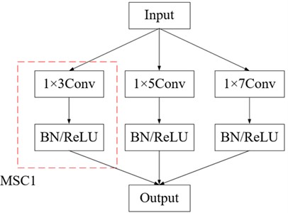
Traditional CNN uses a convolution kernel with a single scale to extract features, because it can only extract a single type of fault feature information, which leads to poor diagnosis effect in noisy environment. Therefore, a MCNN module is designed to increase the receptive field of the network and make full use of the excellent feature learning ability of CNN convolution kernel to extract multi-scale feature information from vibration signals. Its structure is shown in Fig. 1, which mainly consists of three convolution kernels with different scales, namely MSC1, MSC2 and MSC3, and three MSC modules are connected in parallel. The convolution kernels are 1×3, 1×5 and 1×7, respectively [21].
Fig. 1Multiscale convolution
2.1.3. Multiscale residual module
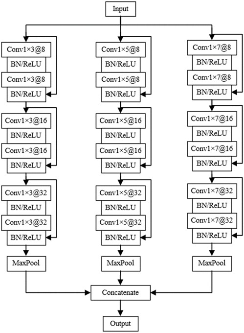
Due to the influence of working environment, the vibration signals collected by rotating machinery have the characteristics of noise, variable working conditions and complexity, and often need deep structure to extract representative information, but deep structure may cause network degradation. Therefore, a kind of MSResNet module is constructed, and its structure is shown in Fig. 2. Each MSC module is embedded with three ResNet modules, and 8 16 and 32 are set as convolution kernels of three ResNet modules, and each ResNet module contains two convolution layers. After each convolution layer, a batch standardization layer is added to standardize the batch processing of network data. A pooling layer is added after each MSC module to ensure the robustness of frame conversion and reduce the weight parameters. The features extracted by three parallel MSC modules are fused as the input of the next layer.
Fig. 2Multiscale residual module
2.2. Attention mechanism
Convolutional Neural Networks (CNN) may extract various features from the input data, some of which may not be relevant to the specific task at hand, such as fault detection [22-23]. Different convolutional filters have varying degrees of recognition of these features, which can sometimes lead to misjudgment in the final output.
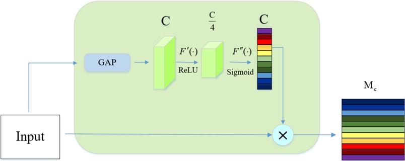
To address this issue, Class Activation Mapping (CAM) technique can be employed to obtain the characteristic information of each channel in the network [24-25]. By multiplying this information with the output characteristics of the upper layer, CAM effectively weights each channel, enhancing the relevant and useful features while suppressing redundant or irrelevant information. This adaptive approach helps in eliminating noise and other invalid features that may interfere with the accuracy of the model.
As shown in Fig. 3, the structure of CAM allows to pay attention to important characteristics in a targeted manner, thus improving the overall performance and accuracy of convolutional networks:
where represents input, represents dimension information of input matrix, represents global tie pooling operation to extract feature channel information to obtain a set of weight information, and represents features after pooling operation:
where represents the activation function, and represent two fully connected layers, reduces the dimension, recovers its dimension, and its channels are coded, and is the Sigmoid function, giving each channel a weight.
denotes scaling operation, which multiplies the weight generated by each channel with each feature of the previous layer, as shown in the Eq. (4):
Fig. 3CAM module
2.3. Overall network structure
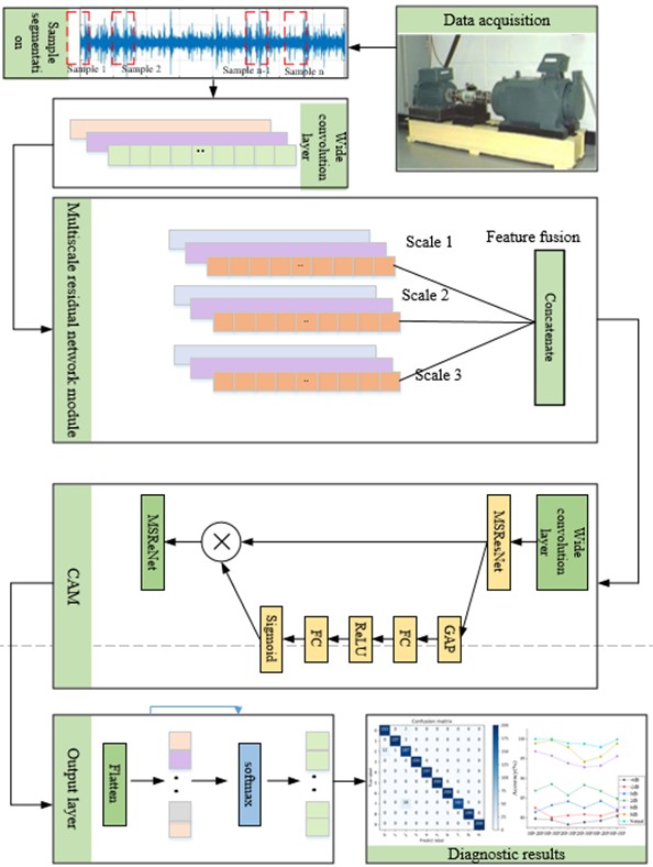
Firstly, the collected original time domain signal is directly used as the input of MSResNet-CAM to realize end-to-end fault diagnosis and avoid the limitation of feature extraction by manual experience. The input vibration signal is convolved by the first layer width to complete the preliminary feature learning. Multi-scale convolution layer is introduced and combined with ResNet to avoid the decline of network performance. MCNN not only increases the receptive field of the network, but also extracts some redundant information unrelated to the fault, which will directly affect the diagnostic performance of the model. Therefore, a layer of wide convolution and CAM module is added after MSResNet fusion to weight the channels, thus eliminating the interference of invalid feature information and redundant information. Finally, the fault identification of rotating machinery equipment is carried out through FC layer and softmax classifier. A fault diagnosis model of rotating machinery based on MSResNet-CAM is constructed, and its structure is shown in Fig. 4. The main structure based on MSResNe-CAM model is shown in the Table 1.
Table 1Structural parameters of MSResNe-CAM
Block | Layer | Operate | Details |
Input layer | 1 | 1×1024 | |
CNN | 1 | Convolution | 1×1024 |
2 | Batch normalization | 16×128 | |
3 | Activation | ReLU | |
MSResNet | Multiscale | Convolution | 1×3 @ 64 |
1×5 @ 64 | |||
1×7 @ 64 | |||
Concatenate | 64×192 | ||
CAM | Global average pooling | 64 | |
Dense | 64 | ||
Activation | relu | ||
reshape | 1×64 | ||
Multiply | 32×64 | ||
Output | Flattened | 1×128 | |
Softmax | 1×10 |
Fig. 4MSResNet feature fusion and CAM diagnosis process
The specific steps are as follows.
Step 1: Collect vibration signals through sensors installed on rotating parts.
Step 2: The collected diagnosis signals are used as input samples to realize end-to-end fault diagnosis.
Step 3: Firstly, the first layer wide convolution is used to complete the preliminary feature learning of the input information. Then, the multi-scale feature extraction is completed by MSC-ResNet, and finally the feature screening is carried out by the CAM module.
Step 4: Back propagation is used to optimize the network parameters, complete the model training and save the model.
Step 5: Input the test set into the trained MSResNet-CAM model, and output the fault types by using the softmax function.
3. Experimental verification
In order to verify the effectiveness of MSResNet-CAM, the rolling bearing CWRU data set and QPZZ-II gear box data set are used to verify the effectiveness of the proposed method. Firstly, the anti-noise performance and fault identification ability of MSResNet-CAM are verified by experiments on two sets of noisy data sets. The generalization performance of MSResNet-CAM is verified by CWRU data sets under different loads.
3.1. CWRU dataset
3.1.1. Experimental data set
Verify the fault diagnosis performance of MSResNet-CAM with the CWRU data set. The main components of the rolling bearing test-bed are motor, sensor and dynamometer. The test-bed is mainly composed of motor, sensor and dynamometer [26]. The test bearing is a deep groove ball bearing, and the sampling frequency is 12 kHz. In the experiment, 120,000 data points were collected as the input of the original signal. In order to ensure the reliability of the data set, the length of each sample is set to 1024 data points. In order to increase the number of samples, overlapping sampling is carried out by shifting and sliding at equal intervals. The window size is 2048 and the step size is 28. The three load conditions are 1HP, 2HP and 3HP respectively. HP is used to simulate the actual load. 1HP, 2HP and 3HP represent different load levels. The collected vibration signals are divided into normal state, inner ring fault, outer ring fault and steel ball fault. There are three types of faults with diameters of 0.1778 mm, 0.3556 mm and 0.5334 mm respectively. There are 10 status labels (1 health label and 9 fault labels). Select 1000 samples for each fault and divide them into training set, verification set and test set according to the ratio of 7:2:1.
Fig. 5The confusion matrix results of different load fault classification are a) 1HP, b) 2HP
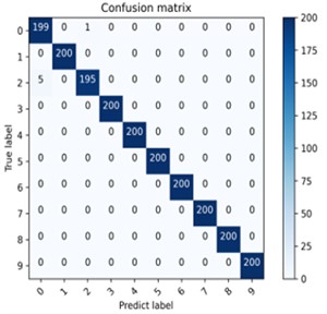
a) 1HP
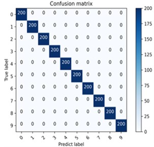
b) 2HP
The fault identification ability of the proposed model is evaluated by using the confusion matrix, and the fault classification results under different loads are obtained. Each health state has 200 test samples, and 10 health states have 2000 test samples. As can be seen from Fig. 5, the fault diagnosis rates of MSResNet-CAM under different loads are 99.7 % and 100 % respectively. In the 1HP experiment, except for a few misjudgments in two states, other fault types were predicted correctly. In the 2HP experiment, all 2000 test samples of 10 health states were predicted correctly. It can be seen that MSResNet-CAM has excellent fault identification ability.
3.1.2. Noise immunity analysis
Under actual working conditions, the rotating system of rotating machinery is often affected by noise environment, so it is very important to have high fault identification ability in noise environment. Gaussian noise is added to the original signal of CWRU data set to simulate the noise environment. In order to verify the diagnostic performance in strong noise environment, the original signal is used as the training set to train the model, and the composite signal with Gaussian noise is used as the test set for verification and evaluation. Signal-to-noise ratio (SNR) is a measurement used to evaluate the level of signal interference caused by noise. It is represented by Eq. (5):
where, and represent original signal power and noise signal power.
is the original signal, and a noise sequence whose probability density function satisfies quasi-Gaussian distribution is generated. Then the original signal power is calculated by the following Eq. (6):
Secondly, given different signal-to-noise ratios, the noise power can be calculated by the following Eq. (7):
Finally, the noise sequence with different signal-to-noise ratios can be calculated by the following Eq. (8):
Noise with different signal-to-noise ratios is added to the original signal in normal and healthy state. As can be seen from Fig. 6 of the time domain waveform, the smaller the signal-to-noise ratio, the greater the fluctuation and the greater the interference to the original signal.
In order to verify the anti-noise performance of the proposed model MSLSTM-CAM, the effectiveness of the MSLSTM-CAM model is verified by comparing and analyzing the experimental results of the same data set with three advanced deep learning models.
(1) Model 1, multi-scale CNN-LSTM and depth residual learning model: This model combines multi-scale CNN and LSTM, and then adds depth residual module [27].
(2) Model 2: Multi-domain signal processing and one-dimensional extended CNN model: This model is preprocessed by signal processing techniques in time domain, frequency domain and time-frequency domain, and then input into the extended CNN [28].
(3) Model 3, multi-scale expansion convolution and residual channel attention mechanism model: This model combines expansion convolution module and multi-scale convolution to form multi-scale expansion convolution module, and then adds residual channel attention mechanism module [29].
Fig. 6The time domain waveforms after adding different signal-to-noise ratios are a) 0 db, b) 4 db

a) 0 dB

b) 4 dB
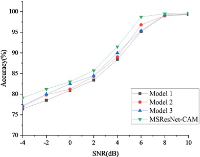
The above three models and the proposed model are tested on the same data set. Gaussian noise is added to the original signal as the test set for experimental comparison, and the interval of adding Gaussian noise is [–4 dB, 10 dB]. The experimental results are shown in Fig. 7, from which it can be seen that the diagnostic accuracy of MSResNet-CAM model is the highest in the whole SNR range. When the signal-to-noise ratio of strong noise is –4, the diagnostic accuracy of MSResNet-CAM is at least 3 % higher than the other three models, especially when the signal-to-noise ratio is above 0dB, the diagnostic accuracy of MSResNet-CAM is close to 100 %. It is verified that MSResNet-CAM has strong anti-noise performance.
Fig. 7Comparison of diagnostic accuracy of signals with different SNR
3.1.3. Anti-noise performance under different loads
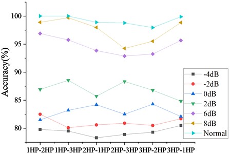
Under actual working conditions, the transmission system of rotating machinery not only works in a noisy environment, but also in changeable loads. Therefore, it is very important to maintain good diagnosis effect under variable load conditions. Noise signals with different signal-to-noise ratios are added to CWRU data sets for experimental verification, and three data sets under different loads are selected to verify the anti-noise performance of the model under variable loads. In addition, the original signal is still used as the training model, and the composite signal with noise is used as the test set for experimental evaluation. Taking 1HP and 2HP as examples, the model is trained with 1HP original data set and tested with 2HP plus noise data set, and the test result is an average of 20 calculations. The experimental results are shown in Fig. 8. When the signal-to-noise ratio of strong noise is –4 dB. The average diagnostic accuracy of variable load is 79 %. When the signal-to-noise ratio is 2 dB, the average diagnostic accuracy of variable load is 83 %. When the signal-to-noise ratio is 6 dB and 10 dB, the accuracy is obviously improved, and the average accuracy reaches ninety-seven percent. In the experiment of noise-free variable load migration, the average accuracy rate is as high as 99 %. Therefore, it is verified that MSResNet-CAM has good noise resistance and stability in variable load migration.
Fig. 8Comparison of diagnostic accuracy under different working conditions
3.1.4. Ablation experiment
In order to visually show the contribution of each branch network of MSResNet-CAM, ablation experiments were conducted by comparing MSResNet-CAM, multi-scale convolution (MSCNN), multi-scale residual (MSResNet) and channel attention convolution neural network (CNN-CAM). The structure of the comparison network is shown in Table 2. In order to ensure the rigor of the experiment, all training parameters are the same. The results of the variable load experiment are listed in Table 3.
Table 2Branch structure details of ablation experiment
Network structure | |||
Algorithm | Multiscale learning | Residual module | CAM |
MSResNet-CAM | yes | yes | yes |
MSCNN | yes | no | no |
MSResNet | yes | yes | yes |
CNN-CAM | no | no | yes |
Table 3Diagnostic accuracy of variable load in CWRU
Source domain and destination domain | Average accuracy(%) | ||||||
Algorithm | 1HP→2HP | 1HP→3HP | 2HP→1HP | 2HP→3HP | 3HP→1HP | 3HP→2HP | |
MSResNet-CAM | 99.8±0.1 | 99.8±0.1 | 98.8±0.3 | 98.6±0.3 | 99.8±0.2 | 97.9±0.3 | 99.1 |
MSCNN | 98.1±0.2 | 98.3±0.2 | 96.8±0.3 | 96.3±0.3 | 97.5±0.2 | 96.6±0.3 | 97.2 |
MSResNet | 98.8±0.3 | 98.5±0.2 | 97.6±0.3 | 97.8±0.3 | 98.3±0.2 | 97.5±0.2 | 98.1 |
MSCNN-CAM | 98.3±0.1 | 98.8±0.2 | 97.8±0.2 | 98.3±0.3 | 98.5±0.2 | 97.5±0.3 | 98.2 |
The experimental results show that the average accuracy of MSResNet-CAM in the variable load experiment is 99.1 %, which is the highest among all the networks participating in the comparison. The average accuracy of MSResNet is 98.1 %, which is 9 % higher than that of MSCNN, which shows that the addition of residual blocks improves the depth of the network and can extract deeper features. The average accuracy of MSCNN-CAM is 98.2 %, which is 10 % higher than that of MSCNN, which shows that the CAM module plays a role in eliminating feature interference unrelated to fault information. In addition, we also carried out ablation experiments under different load noise environments of 1HP and 2HP, and the experimental results are shown in Fig. 9. As can be seen from the figure, in different load noise environments, the accuracy of the proposed MSResNet-CAM is the highest, and the diagnostic accuracy of both MSResNet and MSCNN-CAM is higher than that of MSCNN, indicating that the ResNet module and CAM module have played an important role in it.
Fig. 9The diagnostic results of ablation experiments under different loads were a) 1HP, b) 2HP
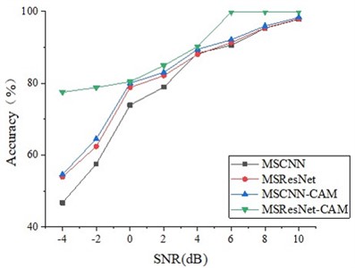
a) 1HP
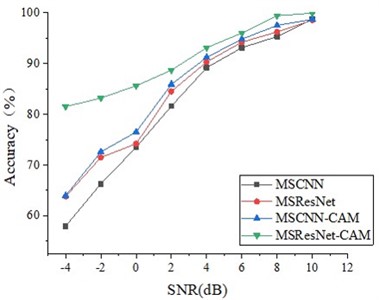
b) 2HP
In addition, the is adopted to assess the influence of various models on different classes in this study, and it can be represented as follow:
where, and denote recall and precision rate, respectively, and represent true and false positive, respectively, is false negative. After calculation, the of all models is shown in Fig. 10.
Fig. 10F1-score scores of different methods
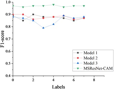
The fault state identification performance of the proposed method and the other three excellent methods is shown in Fig. 10. It can be seen from the experimental results that the -point value of the proposed method is higher than the other three methods. Therefore, it can be further proved that the proposed network model has good generalization performance.
3.2. QPZZ-II gearbox data set
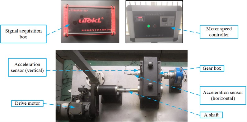
In order to verify the effectiveness of MSResNet-CAM in fault diagnosis of rotating machinery more comprehensively, gear fault diagnosis is carried out by using QPZZ-II vibration analysis and fault diagnosis test-bed for rotating machinery to collect gear signals. The test-bed is mainly composed of driving motor, gearbox, sensor, signal acquisition box and other components. QPZZ-II vibration analysis and fault diagnosis test-bed for rotating machinery is shown in Fig. 11.
The acceleration level sensor installed in the horizontal direction of the gearbox is used to collect data, and 120,000 data points are collected. And take the original data as the input of the network. The test gears include normal gears, single-tooth crack fault gears, double-tooth crack fault gears, single-tooth pitting fault gears and double-tooth pitting fault gears. The fault degree of the same fault type is also different, with a total of 10 status labels (1 health status label and 9 fault labels). Each type of fault signal contains 1000 samples, totaling 10000 samples, which are still divided into training set, test set and verification set according to the ratio of 7: 2: 1. The test data acquisition frequency is 12.8 kHz, and the motor load is 0 horsepower.
Fig. 11Vibration analysis and fault diagnosis test bench of QPZZ-II rotating machinery
Firstly, the fault identification ability of the proposed model is verified by experiments under the condition of no noise, and confusion matrix visualization is still used for evaluation. The experimental results are shown in Fig. 12. Except for a few misjudgments of some tags, all the other tags are correctly predicted, and the fault identification accuracy reaches 99.3 %. Although there are differences in data sets, it still has high accuracy in gearbox fault diagnosis, which shows that MSResNet-CAM has good robustness.
In order to further verify the superiority of the proposed method, we use QPZZ-II data set for experimental verification. Gaussian noise is added to the original vibration signal, and the signal-to-noise ratio range is [–4 dB, 10 dB]. Compared with the above three advanced deep learning methods, the original signal is used as the training model and the noisy composite signal is used as the test set for verification. The experimental results are shown in Fig. 13. The diagnostic accuracy of MSResNet-CAM is higher than other methods in all signal-to-noise ratios, especially when the signal-to-noise ratio of strong noise is –4 dB, the diagnostic accuracy is more than 2 % higher than other methods. Although the experimental data are quite different, it still has high diagnostic accuracy under strong noise conditions. It shows that MSResNet-CAM has good anti-noise, stability and versatility.
Fig. 12Results of confusion matrix for fault classification under gearbox data set
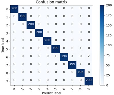
Fig. 13Diagnostic results of gearbox data set in different signal-to-noise ratios
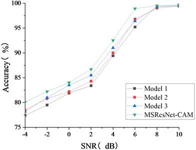
Fig. 14Diagnostic accuracy of ablation experiment under QPZZ-II data set
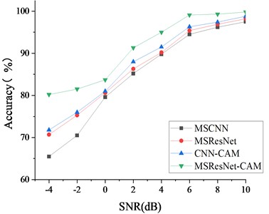
Similar to the above CRWU data set experiment, the ablation experiment was carried out by comparing MSResNet-CAM, MSCNN, MSResNet and CNN-CAM, and Gaussian noise was added to QPZZ-II vibration signal to simulate the noise environment. Similarly, we trained the model with the original vibration signal and verified it with the composite signal with noise signal as the test set. The experimental results are shown in the Fig. 14, and it can be seen from the figure that when the signal-to-noise ratio of strong noise is –4 dB, the diagnostic accuracy of MSResNet-CAM is 80.3 %, which is the highest among all comparison methods. The diagnostic accuracy of MSResNet is 5.2 % higher than that of MSCNN, and that of CNN-CAM is 6.3 % higher than that of MSCNN. It shows that ResNet stack module and CAM module play a role and have anti-noise performance.
4. Conclusions
In this paper, a fault diagnosis method of rotating machinery under strong noise condition based on MSResNet feature fusion and CAM is proposed. Firstly, multi-scale convolution is combined with residual network, and residual connection is introduced to prevent network degradation and extract deep features. After MSResNet feature fusion, in order to avoid the interference of redundant information, CAM module is added to adaptively pay attention to important features and remove the interference of features unrelated to fault information. The MSResNet-CAM model is verified on CWRU bearing data set and QPZZ-II gearbox data set. The experimental results show that the average accuracy rate reaches 99.1 % under different loads of CWRU data sets. When the signal-to-noise ratio of strong noise is –4 dB, the diagnostic accuracy is 79 %. Under the condition of variable load, when the signal-to-noise ratio is greater than 4 dB, the diagnostic accuracy is over 92 %. These results prove that the MSResNet-CAM model has strong anti-noise performance and domain adaptability. In addition, this method performs well on QPZZ-II transmission data sets, with the diagnostic accuracy of 99.7 % under noise-free conditions and 80.5 % under strong noise signal-to-noise ratio of –4 dB. Compared with other advanced deep learning methods, this method performs best in accuracy, robustness and extrapolation effect. This series of experiments show that the MSResNet-CAM model has excellent performance in noise immunity, robustness and generalization ability, and has important theoretical value and development potential for fault diagnosis of rotating machinery in practical industrial applications.
Although the MSResNet-CAM model proposed in this paper has made remarkable achievements in fault diagnosis of rotating machinery, it also has some shortcomings. For example, although the model can extract deep features and deepen the network structure, it also increases the training time of the network. Therefore, future research will focus on reducing training time to improve the practical application efficiency of the model.
References
-
B. H. Ahn, Y. H. Kim, J. M. Lee, J. M. Ha, and B. K. Choi, “Signal-processing technology for rotating machinery fault signal diagnosis,” Progress in Clean Energy, Volume 1, Vol. 24, No. 7, pp. 933–943, Jan. 2015, https://doi.org/10.1007/978-3-319-16709-1_67
-
R. Liu, B. Yang, E. Zio, and X. Chen, “Artificial intelligence for fault diagnosis of rotating machinery: A review,” Mechanical Systems and Signal Processing, Vol. 108, pp. 33–47, Aug. 2018, https://doi.org/10.1016/j.ymssp.2018.02.016
-
Y. Li, K. Ding, G. He, and X. Jiao, “Non-stationary vibration feature extraction method based on sparse decomposition and order tracking for gearbox fault diagnosis,” Measurement, Vol. 124, pp. 453–469, Aug. 2018, https://doi.org/10.1016/j.measurement.2018.04.063
-
L. Wan, Y. Chen, H. Li, and C. Li, “Rolling-element bearing fault diagnosis using improved LeNet-5 network,” Sensors, Vol. 20, No. 6, p. 1693, Mar. 2020, https://doi.org/10.3390/s20061693
-
M. Demetgul, K. Yildiz, S. Taskin, I. N. Tansel, and O. Yazicioglu, “Fault diagnosis on material handling system using feature selection and data mining techniques,” Measurement, Vol. 55, pp. 15–24, Sep. 2014, https://doi.org/10.1016/j.measurement.2014.04.037
-
N. F. Waziralilah et al., “A review on convolutional neural network in bearing fault diagnosis,” in MATEC Web of Conferences, Vol. 255, p. 06002, Jan. 2019, https://doi.org/10.1051/matecconf/201922555506002
-
T. Young, D. Hazarika, S. Poria, and E. Cambria, “Recent trends in deep learning based natural language processing [Review Article],” IEEE Computational Intelligence Magazine, Vol. 13, No. 3, pp. 55–75, Aug. 2018, https://doi.org/10.1109/mci.2018.2840738
-
Y. Lecun, L. Bottou, Y. Bengio, and P. Haffner, “Gradient-based learning applied to document recognition,” Proceedings of the IEEE, Vol. 86, No. 11, pp. 2278–2324, Jan. 1998, https://doi.org/10.1109/5.726791
-
L. Eren, “Bearing fault detection by one‐dimensional convolutional neural networks,” Mathematical Problems in Engineering, Vol. 2017, No. 1, p. 86173, Jul. 2017, https://doi.org/10.1155/2017/8617315
-
W. Zhang, C. Li, G. Peng, Y. Chen, and Z. Zhang, “A deep convolutional neural network with new training methods for bearing fault diagnosis under noisy environment and different working load,” Mechanical Systems and Signal Processing, Vol. 100, pp. 439–453, Feb. 2018, https://doi.org/10.1016/j.ymssp.2017.06.022
-
S. Hao, F.-X. Ge, Y. Li, and J. Jiang, “Multisensor bearing fault diagnosis based on one-dimensional convolutional long short-term memory networks,” Measurement, Vol. 159, No. 15, p. 107802, Jul. 2020, https://doi.org/10.1016/j.measurement.2020.107802
-
F. Li, L. Wang, D. Wang, J. Wu, and H. Zhao, “An adaptive multiscale fully convolutional network for bearing fault diagnosis under noisy environments,” Measurement, Vol. 216, p. 112993, Jul. 2023, https://doi.org/10.1016/j.measurement.2023.112993
-
K. Zhang, C. Fan, X. Zhang, H. Shi, and S. Li, “A hybrid deep-learning model for fault diagnosis of rolling bearings in strong noise environments,” Measurement Science and Technology, Vol. 33, No. 6, p. 065103, Jun. 2022, https://doi.org/10.1088/1361-6501/ac4a18
-
Y. Zhang, W. Liu, X. Wang, and H. Gu, “A novel wind turbine fault diagnosis method based on compressed sensing and DTL-CNN,” Renewable Energy, Vol. 194, pp. 249–258, Jul. 2022, https://doi.org/10.1016/j.renene.2022.05.085
-
H. Qin, J. Pan, J. Li, and F. Huang, “Fault diagnosis method of rolling bearing based on CBAM_ResNet and ACON activation function,” Applied Sciences, Vol. 13, No. 13, p. 7593, Jun. 2023, https://doi.org/10.3390/app13137593
-
D. Yao, H. Liu, J. Yang, and X. Li, “A lightweight neural network with strong robustness for bearing fault diagnosis,” Measurement, Vol. 159, p. 107756, Jul. 2020, https://doi.org/10.1016/j.measurement.2020.107756
-
T. Xu, H. Lv, S. Lin, H. Tan, and Q. Zhang, “A fault diagnosis method based on improved parallel convolutional neural network for rolling bearing,” Proceedings of the Institution of Mechanical Engineers, Part G: Journal of Aerospace Engineering, Vol. 237, No. 12, pp. 2759–2771, Feb. 2023, https://doi.org/10.1177/09544100231158421
-
Y. Zhang, J. Ye, W. Yang, J. Shi, W. He, and G. Cai, “A novel sparse enhancement neural network for rolling bearing fault diagnosis,” Shock and Vibration, Vol. 2022, No. 1, pp. 1–12, Oct. 2022, https://doi.org/10.1155/2022/8552388
-
Z. Liu, P. Zhang, Y. Yu, M. Li, and Z. Zeng, “A novel fault diagnosis model of rolling bearing under variable working conditions based on attention mechanism and domain adversarial neural network,” Journal of Mechanical Science and Technology, Vol. 38, No. 3, pp. 1101–1111, Mar. 2024, https://doi.org/10.1007/s12206-024-1208-8
-
K. He, X. Zhang, S. Ren, and J. Sun, “Deep residual learning for image recognition,” in IEEE Conference on Computer Vision and Pattern Recognition (CVPR), Jun. 2016, https://doi.org/10.1109/cvpr.2016.90
-
X. Zhao and Y. Zhang, “An intelligent diagnosis method of rolling bearing based on multi-scale residual shrinkage convolutional neural network,” Measurement Science and Technology, Vol. 33, No. 8, p. 085103, Aug. 2022, https://doi.org/10.1088/1361-6501/ac68d1
-
M. Cakar, K. Yildiz, and Y. Genc, “Multi adaptive hybrid networks (MAHNet): ensemble learning in convolutional neural network,” in IEEE Asia-Pacific Conference on Computer Science and Data Engineering (CSDE), Dec. 2021, https://doi.org/10.1109/csde53843.2021.9718464
-
M. Çakar, K. Yildiz, and Demir, “Thumbnail selection with convolutional neural network based on emotion detection,” International Journal of Advances in Engineering and Pure Sciences, Vol. 33, pp. 88–93, Dec. 2021, https://doi.org/10.7240/jeps.900561
-
H. Jiang, F. Wang, H. Shao, and H. Zhang, “Rolling bearing fault identification using multilayer deep learning convolutional neural network,” Journal of Vibroengineering, Vol. 19, No. 1, pp. 138–149, Feb. 2017, https://doi.org/10.21595/jve.2016.16939
-
Y.-J. Huang, A.-H. Liao, D.-Y. Hu, W. Shi, and S.-B. Zheng, “Multi-scale convolutional network with channel attention mechanism for rolling bearing fault diagnosis,” Measurement, Vol. 203, p. 111935, Nov. 2022, https://doi.org/10.1016/j.measurement.2022.111935
-
“Case Western Reserve University Bearing Data Center”, https://cse.groups.case.edu/bearingdatacenter/pages/download-data-file
-
H. Chen, W. Meng, Y. Li, and Q. Xiong, “An anti-noise fault diagnosis approach for rolling bearings based on multiscale CNN-LSTM and a deep residual learning model,” Measurement Science and Technology, Vol. 34, No. 4, p. 045013, Apr. 2023, https://doi.org/10.1088/1361-6501/acb074
-
K. Dong and A. Lotfipoor, “Intelligent bearing fault diagnosis based on feature fusion of one-dimensional dilated CNN and multi-domain signal processing,” Sensors, Vol. 23, No. 12, p. 5607, Jun. 2023, https://doi.org/10.3390/s23125607
-
H. Sun, X. Cao, C. Wang, and S. Gao, “An interpretable anti-noise network for rolling bearing fault diagnosis based on FSWT,” Measurement, Vol. 190, p. 110698, Feb. 2022, https://doi.org/10.1016/j.measurement.2022.110698
About this article
The authors have not disclosed any funding.
The datasets generated during and/or analyzed during the current study are available from the corresponding author on reasonable request.
The authors declare that they have no conflict of interest.
