Abstract
In recent years, power equipment has been developing towards low-carbon, high-efficiency, and green environmental protection. The double reheat unit has been increasingly employed in power plants due to its advantages of low energy consumption and less pollution. As a core component of power plants, the dynamic performance analysis of the steam turbine foundation is essential for ensuring the overall safety of double reheat unit. For this reason, the dynamic performance of a steam turbine foundation is investigated based on the engineering background of frame-type reinforced concrete foundations of 1000 MW double reheat steam turbine set in a power plant. The solid finite element model of the steam turbine foundation is first established by using ANSYS software, along with a detailed description of foundation information and modelling methodology. Subsequently, the dynamic characteristic and response analyses of the steam turbine foundation are performed to evaluate its dynamic performance, respectively. The results indicate that the 1000 MW steam turbine foundation demonstrates satisfactory dynamic performance. Within the operating speed range, the transverse, longitudinal, and vertical vibration displacements of the foundation bearings and columns remain below 20 μm, while the vibration velocity does not exceed 3.8 mm/s, both of which comply with relevant specifications. Moreover, enhancing the stiffness of the fifth and sixth beams, along with increasing the cross-sectional area of columns C3 and C4 on the steam turbine foundation, should be considered to mitigate its vibration responses and thus improve its dynamic performance. The research findings can serve as a reference for the type selection and optimization design of 1000 MW double reheat steam turbine foundations.

Highlights
- A solid finite element model of steam turbine foundation is established by using ANSYS software.
- The dynamic performance of steam turbine foundation is comprehensively assessed through dynamic characteristic and response analyses.
- The research findings can serve as a reference for the type selection and optimization design of 1000 MW double reheat steam turbine foundations.
1. Introduction
In recent years, China’s energy sector has been undergoing a low-carbon transition, with power engineering and equipment advancing toward low-carbon, high-efficiency, green, environmentally friendly, safe, and reliable development [1-3]. To address the high energy consumption and heavy pollution associated with traditional thermal power units, large-capacity ultra-supercritical units are increasingly being adopted. These new units, characterized by high steam parameters, large unit capacity, high power generation efficiency, and low unit capacity cost, have become a key option for thermal power generation. The steam turbine is the core component of nuclear and thermal power plants and is classified as high-precision equipment, which is characterized by numerous components, complex installation, high-precision requirements, and stringent vibration and shock control requirements [4, 5]. As a critical supporting structure, the appropriate selection and design of the steam turbine foundation can effectively control its vibration responses induced by disturbing forces from operating steam turbines. Therefore, analyzing the dynamic performance of the steam turbine foundation is crucial for guiding the selection of foundation types and optimizing the design [6-8].
There are generally two types of steam turbine foundations: rigid frame foundations and spring isolation foundations [9-11]. The selection of foundation type is influenced by factors such as unit capacity, structural characteristics, isolation requirements, and site conditions. Most domestic 1000 MW single-shaft four-cylinder full-speed units utilize rigid frame foundations due to their high structural integrity and load-bearing capacity. In contrast, nuclear power half-speed units and international single-shaft five-cylinder units generally adopt spring isolation foundations to effectively mitigate vibration transmission and enhance operational stability. With the continuous advancement of ultra-supercritical technology and the increasing demand for high-efficiency, low-emission power generation, the application of spring vibration isolation foundations has become more prevalent in large-scale thermal power plants. Currently, the steam turbine generator foundations of 1000 MW ultra-supercritical double-reheat coal-fired units in operation, including the second phase of the Guodian Taizhou Power Plant, Huaneng Laiwu, Huadian Laizhou, Huadian Jurong, and Datang Dongying, all employ spring vibration isolation foundations.
To investigate the dynamic characteristics of various steam turbine foundations, Guo and Song [12] employed ANSYS software to develop a solid finite element model and SAP2000 software to construct a rod finite element model of a 600 MW steam turbine foundation. They compared the applicability of both finite element models and identified a foundation structure with favorable dynamic characteristics for steam turbine units, providing a reference for similar foundation designs. An [13] used SeismoStruct software to model the spring-isolated foundation of a steam turbine generator unit and conducted a time-history analysis, examining frequency vibration modes, seismic responses, interlayer deformations, spring deformations, and other key characteristics. Chen et al. [14] studied the joint arrangement spring foundation of a 1000 MW coal-fired demonstration power plant. They developed a finite element model in ANSYS, performed an earthquake time-history analysis, and utilized ANSYS’s built-in optimization module and algorithm to refine the foundation design. Li et al. [15] analyzed the high-frequency vibration of an ultra-supercritical 1000 MW steam turbine and proposed a method for troubleshooting its spring group. Du et al. [16] investigated the dynamic performance of a 1000MW secondary reheating unit using a combination of numerical simulations and physical model experiments. However, the complex structure of the steam turbine foundation and the constraints imposed by equipment size on its external dimensions make foundation design challenging, particularly for new units. Numerical analysis is typically required to assess whether the dynamic characteristics and responses of the steam turbine foundation meet operational requirements.
Given the above fact, this study takes the rigid frame foundation of a five-cylinder, four-exhaust, double back-pressure condensing 1000 MW steam turbine as the research background, and conducts a comprehensive numerical analysis to investigate the dynamic performance of the steam turbine foundation, focusing on its vibration characteristics and responses under operational loads. The analysis aims to evaluate whether its dynamic characteristics and responses meet operational requirements, providing a reference for the type selection and optimization design of 1000 MW double reheat steam turbine foundations. The rest of this article is structured as follows. Section 2 establishes a solid finite element model of the steam turbine foundation, along with a detailed description of foundation information and modelling methodology; To assess the dynamic performance of the steam turbine foundation, its dynamic characteristic analysis is performed in Section 3, followed by its dynamic response analysis in Section 4; finally, some conclusions are drawn in Section 5.
2. Finite element modelling of steam turbine foundation
2.1. Foundation information
The 1000 MW double reheat low-pressure cylinder unit of a power plant operates at a rated speed of 3000 r/min. The steam turbine system consists of one ultra-high-pressure cylinder, one high-pressure cylinder, one intermediate-pressure cylinder, and two low-pressure cylinders. The foundation platform of the steam turbine measures 53.4 m in length, with the foundation at its end spanning 16.0 m in width. The center elevation of the steam turbine generator bearing is 18.0 m, the bottom elevation of the platform is 13.5 m, and the bottom elevation of the column is –2.5 m. The concrete strength grade is C40. Figs. 1 and 2 show the plane drawing and sectional drawing of the steam turbine foundation, and the weight of bearings is tabulated in Table 1.
Fig. 1Plane drawing of the steam turbine foundation
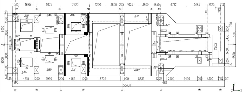
Fig. 2Sectional drawing of the steam turbine foundation
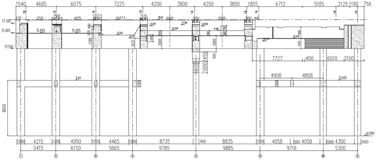
Table 1Weight of bearings
No. | W1 | W2 | W3 | W4 | W5 | W6 | W7 | W8 | W9 |
Weight (kN) | 63.5 | 190 | 382 | 785 | 1066 | 513 | 450 | 450 | 13 |
2.2. Modelling methodology
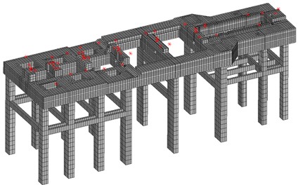
Fig. 3 illustrates the solid finite element model of the steam turbine foundation, established by using ANSYS software. Thereinto, the turbine's top plate, columns, and intermediate platform were modeled with Solid95 elements, while Beam188, Mass21, and Surf154 elements were used to simulate the intermediate platform’s steel beams, additional equipment mass, and the secondary casting layer, respectively. The secondary casting layer primarily functioned as a massless stiffness block of a certain thickness at the equipment mass, preventing localized ambiguous vibration modes. Cerig and Rbe3 auxiliary elements were employed to connect the mass to platform nodes, simulating the rigid domain of the equipment mass to enhance its stiffness and mitigate the rotor’s vibration response. In addition, the nodes at the base of the columns were fixed to ensure structural stability.
Fig. 3Solid finite element model of the steam turbine foundation
2.3. Dynamic characteristic analysis of steam turbine foundation
To evaluate the dynamic performance of the steam turbine foundation, the dynamic characteristics of the turbine generator foundation are computed through modal analysis in ANSYS (version 2021 R1). In general, the cut-off frequency for foundation modal analysis should be 1.4 times the operating frequency of the steam turbine. The operating speed of the steam turbine set in this project is 3000 r/min, corresponding to 50 Hz, resulting in a modal analysis cut-off frequency of 70 Hz. Fig. 4 shows the natural vibration modes of the steam turbine foundation. As shown, the first three vibration modes of the steam turbine foundation correspond to longitudinal translation, torsion, and transverse translation, with vibration frequencies of 1.468 Hz, 1.929 Hz, and 2.059 Hz, respectively. Moreover, the tenth vibration mode of the steam turbine foundation corresponds to the vertical bending of the platform, with a vibration frequency of 11.212 Hz.
Fig. 4Natural vibration modes of the steam turbine foundation
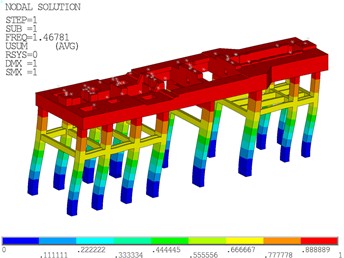
a) Longitudinal translation of the first vibration mode (1.468 Hz)
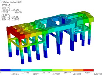
b) Torsion of the second vibration mode (1.929 Hz)
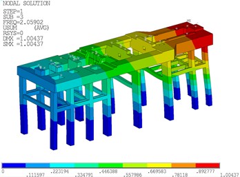
c) Transverse translation of the third vibration mode (2.059 Hz)

d) Vertical bending of the tenth vibration mode (11.212 Hz)
Table 2 lists the mass participation coefficients for the natural vibration modes of the steam turbine foundation. The mass participation coefficients for the longitudinal translation of the first vibration mode, the transverse translation of the third vibration mode, and the vertical bending of the tenth vibration mode are all 100.
Table 2Mass participation coefficients for the natural vibration modes of the steam turbine foundation
Mode order | Frequency (Hz) | Mass participation coefficients | ||
Longitudinal | Transverse | Vertical | ||
1 | 1.468 | 100.00 | 0.00 | 0.08 |
2 | 1.929 | 0.00 | 44.82 | 0.00 |
3 | 2.059 | 0.00 | 100.00 | 0.00 |
10 | 11.212 | 1.18 | 0.00 | 100.00 |
3. Dynamic response analysis of steam turbine foundation
3.1. Vibration loads
To further assess the dynamic performance of the steam turbine foundation, the vibration responses of the turbine generator foundation is computed through harmonic response analysis in ANSYS (version 2021 R1), aiming to determine compliance with relevant specifications. The transverse and vertical disturbing forces are 0.2 times the rotor weight, while the longitudinal disturbing force is 0.1 times the rotor weight. Table 3 presents the disturbing forces on the steam turbine foundation, with disturbing force positions indicated at W1-W9 and C1-C8 in Fig. 5.
Table 3Disturbing forces on the steam turbine foundation
No. | Rotor weight (kN) | Vertical (kN) | Longitudinal (kN) | Transverse (kN) |
1 | 63.5 | 12.7 | 12.7 | 6.4 |
2 | 190.0 | 38.0 | 38.0 | 19.0 |
3 | 382.0 | 76.4 | 76.4 | 38.2 |
4 | 785.0 | 157.0 | 157.0 | 78.5 |
5 | 1066.0 | 213.2 | 213.2 | 106.6 |
6 | 513.0 | 102.6 | 102.6 | 51.3 |
7 | 450.0 | 90.0 | 90.0 | 45.0 |
8 | 450.0 | 90.0 | 90.0 | 45.0 |
9 | 13.0 | 2.6 | 2.6 | 1.3 |
Fig. 5Disturbing force points on the steam turbine foundation

The API 617 Axial and centrifugal compressors and expander-compressors [17] and ISO 20816-2 Mechanical vibration – Measurement and evaluation of machine vibration [18] each provide calculation methods and limit requirements for the vibration displacements at each disturbing force point, as summarized in Table 4.
Table 4Limit values of vibration displacement and velocity in standards for design of dynamic machine foundation
Assess index | Frequency range (Hz) | Combination method | Limit values (μm or mm/s) |
Displacement | 0-37.5 37.5-62.5 62.5-70.0 | SRSS | 25.4 |
Velocity | 45.0-57.5 | 3.8 |
In the calculation of the vibration (line) displacement of the disturbing force point, the disturbing force at any speed can be calculated by:
where is the disturbing force at the rated speed .
When multiple disturbing forces are acting, the vibration displacement at the disturbing force point can be represented as follows:
in which and denote the vibration displacement of the th particle and the vibration displacement generated by the th disturbing force on the th particle, respectively.
Notably, in the harmonic response analysis of the steam turbine foundation, the longitudinal, transverse, and vertical vibration responses at disturbing force points should be computed separately to ensure a comprehensive evaluation of the dynamic performance of the steam turbine foundation. Specifically, under single-direction, single-point sequential loading conditions, the vibration displacement of each disturbing force point is individually computed in response to a single applied disturbing force. To obtain the overall vibration response of a given disturbing force point, the vibration displacements caused by different disturbing forces must be synthesized. This is achieved using the SRSS (Square Root of the Sum of the Squares) method, which accounts for the independent contributions of multiple forces by computing their combined effect in a statistically valid manner.
3.2. Vibration responses of bearings
Fig. 6 illustrates the vibration displacement responses of the bearings on the steam turbine foundation. As illustrated, the transverse, longitudinal, and vertical vibration displacements comply with specification limits, with the transverse and longitudinal displacements being significantly greater than the vertical displacement. As shown in Fig. 6(a), the transverse displacement is prominent within the 0-37.5 Hz and 62.5-70 Hz frequency ranges, whereas it remains minimal in the operating frequency range (37.5-62.5 Hz). Fig. 6(b) reveals that the transverse displacement peak is primarily concentrated within the 0-37.5 Hz frequency range, whereas Fig. 6(c) demonstrates a similar trend for the vertical displacement peak. These findings indicate that the peak vibration displacement of the bearings primarily occurs within the 0-37.5 Hz frequency range. This suggests that vibrations within this frequency band contribute significantly to the dynamic response of the steam turbine foundation, potentially leading to increased mechanical stress and wear on critical components. Therefore, prolonged warm-up operations within this frequency range during start-up should be avoided to mitigate excessive vibration effects. Implementing optimized startup procedures may help minimize resonance effects and improve the overall stability and longevity of the system.
Fig. 6Vibration displacement responses of the bearings on the steam turbine foundation
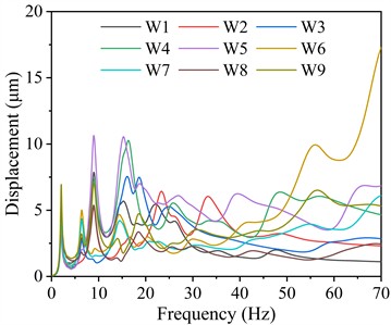
a) Transverse vibration displacement
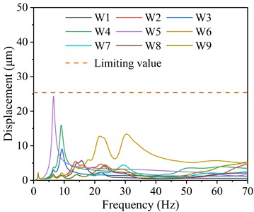
b) Longitudinal vibration displacement

c) Vertical vibration displacement
Table 5Maximum vibration displacement responses of the bearings in different frequency ranges and their corresponding bearing numbers and dominant frequencies
Direction | Frequency range (Hz) | Displacement (μm) | Bearing No. | Frequency (Hz) |
Transverse | 0-37.5 | 10.64 | W5 | 8.97 |
37.5-62.5 | 9.94 | W6 | 56.03 | |
62.5-70.0 | 17.28 | W6 | 70.00 | |
Longitudinal | 0-37.5 | 24.37 | W5 | 6.50 |
37.5-62.5 | 8.08 | W6 | 37.56 | |
62.5-70.0 | 5.53 | W6 | 62.55 | |
Vertical | 0-37.5 | 22.45 | W5 | 15.75 |
37.5-62.5 | 7.10 | W5 | 38.67 | |
62.5-70.0 | 5.91 | W5 | 63.29 |
Table 5 summarizes the maximum vibration displacement responses of the bearings in different frequency ranges and their corresponding bearing numbers and dominant frequencies. For transverse vibration displacement, the maximum value within the 0-37.5 Hz frequency range occurs at W5, reaching 10.64 μm. In the 37.5-62.5 Hz frequency range, W6 exhibits the highest transverse displacement of 9.94 μm, while in the 62.5-70.0 Hz frequency range, it reaches 17.28 μm. Regarding longitudinal vibration displacement, W5 experiences the highest displacement of 24.37 μm in the 0-37.5 Hz frequency range. Within the 37.5-62.5 Hz frequency range, W6 records a maximum displacement of 8.08 μm, whereas in the 62.5-70.0 Hz frequency range, it decreases to 5.53 μm. For vertical vibration displacement, W5 exhibits the highest displacement values across all frequency ranges: 22.45 μm (0-37.5 Hz), 7.10 μm (37.5-62.5 Hz), and 5.91 μm (62.5-70.0 Hz).
Fig. 7Vibration velocity responses of the bearings on the steam turbine foundation
a) Transverse vibration velocity

b) Longitudinal vibration velocity
c) Vertical vibration velocity
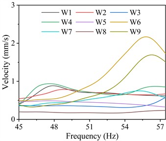
Table 6Maximum vibration velocity responses of the bearings in different frequency ranges and their corresponding bearing numbers and dominant frequencies
Direction | Frequency range (Hz) | Velocity (mm/s) | Bearing No. | Frequency (Hz) |
Transverse | 45.0-57.5 | 2.17 | W6 | 55.77 |
Longitudinal | 1.37 | W9 | 53.93 | |
Vertical | 1.06 | W9 | 53.93 |
Fig. 7 depicts the vibration velocity responses of the bearings on the steam turbine foundation. As depicted, the transverse, longitudinal, and vertical vibration velocities of the bearings comply with specification limits, with their transverse and longitudinal velocities being dramatically greater than the vertical velocity within the 45.0-57.5 Hz frequency range. Table 6 lists the maximum vibration velocity responses of the bearings in different frequency ranges and their corresponding bearing numbers and dominant frequencies. For transverse vibration velocity, the maximum value within the 45.0-57.5 Hz frequency range occurs at W6, reaching 2.17 mm/s. Regarding longitudinal vibration velocity, W9 experiences the highest velocity of 1.37 mm/s in the 45.0-57.5 Hz frequency range. For vertical vibration displacement, W9 exhibits the highest displacement of 1.06 mm/s within the 45.0-57.5 Hz frequency range.
A comprehensive comparative analysis of the transverse, longitudinal, and vertical displacement and velocity responses of the bearings reveals that vibration responses at foundation bearings W5 and W6 are significantly higher than those at other locations. These bearings correspond to the fifth and sixth beams of the steam turbine foundation, suggesting that the structural stiffness in this region is relatively low, which in turn leads to amplified vibration responses. This phenomenon may be attributed to insufficient support, local flexibility, or resonance effects caused by the operational frequency of the steam turbine. Additionally, the observed excessive vibrations could contribute to increased fatigue stress on structural components, potentially leading to long-term durability issues and serviceability concerns. To mitigate these excessive vibrations and improve the overall structural stability of the steam turbine foundation, enhancing the stiffness of the beams in this region should be considered. Potential remedial measures include increasing beam height to enhance flexural rigidity, adding additional support elements such as vertical columns or partition walls to distribute loads more effectively, and optimizing the cross-sectional properties of the beams.
3.3. Vibration responses of columns
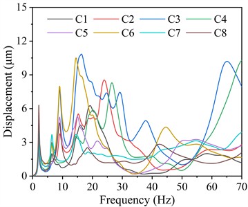
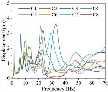
Fig. 8 shows the vibration displacement responses of the columns on the steam turbine foundation. As shown, the vibration displacements of the columns are significantly smaller than that of the bearings, with transverse and vertical displacements being considerably greater than longitudinal displacements. The peak values of the transverse vibration displacements of the columns are concentrated within the 0-37.5 Hz and 62.5-70.0 Hz frequency ranges, while the peak values of its longitudinal and vertical vibration displacements are primarily concentrated in the 0-37.5 Hz frequency band. Similarly, the peak vibration displacement of the columns primarily occurs within the 0-37.5 Hz frequency range, indicating that vibration energy is concentrated within this frequency band. This suggests that during the start-up phase, prolonged operation within this frequency range should be avoided to minimize excessive vibration-induced stress on structural components. Extended exposure to such frequencies may lead to resonance phenomena, amplifying displacement and potentially accelerating material fatigue, which could compromise the structural integrity of the unit over time. Therefore, optimizing the start-up sequence to swiftly transition through this frequency range can effectively mitigate adverse vibration effects and enhance the operational stability and longevity of the system.
Table 7Maximum vibration displacement responses of the columns in different frequency ranges and their corresponding column numbers and dominant frequencies
Direction | Frequency range (Hz) | Displacement (μm) | Column No. | Frequency (Hz) |
Transverse | 0-37.5 | 10.84 | C3 | 16.28 |
37.5-62.5 | 8.49 | C3 | 62.53 | |
62.5-70.0 | 10.29 | C4 | 70.00 | |
Longitudinal | 0-37.5 | 9.06 | C7 | 14.49 |
37.5-62.5 | 3.71 | C8 | 62.43 | |
62.5-70.0 | 3.73 | C8 | 63.05 | |
Vertical | 0-37.5 | 3.60 | C3 | 32.84 |
37.5-62.5 | 1.74 | C4 | 47.66 | |
62.5-70.0 | 2.12 | C7 | 70.00 |
Table 7 tabulates the maximum vibration displacement responses of the columns in different frequency ranges and their corresponding column numbers and dominant frequencies. For transverse vibration displacement, C3 exhibits the highest displacement of 10.84 μm within the 0-37.5 Hz frequency range, whereas it decreases to 8.49 μm within the 37.5-62.5 Hz range. The maximum displacement within the 62.5-70.0 Hz frequency range occurs at C4, reaching 10.29 μm. Regarding longitudinal vibration displacement, C7 exhibits the highest displacement of 9.06 μm within the 0-37.5 Hz frequency range. Within the 37.5-62.5 Hz frequency range, C8 exhibits a maximum displacement of 3.71 μm, whereas within the 62.5-70.0 Hz range, it slightly increases to 3.73 μm. For vertical vibration displacement, C3 exhibits the highest displacement of 3.60 μm within the 0-37.5 Hz frequency range, a lower displacement of 1.74 μm within the 37.5-62.5 Hz range, whereas C7 exhibits an intermediate displacement of 2.12 μm within the 62.5-70.0 Hz range.
Fig. 8Vibration displacement responses of the columns on the steam turbine foundation
a) Transverse vibration displacement
b) Longitudinal vibration displacement

c) Vertical vibration displacement
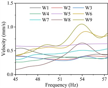
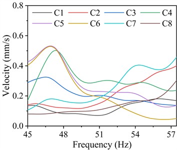
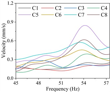
Fig. 9 presents the vibration velocity responses of the columns on the steam turbine foundation. As presented, the transverse, longitudinal, and vertical vibration velocities of the columns comply with specification limits, with their transverse and vertical velocities being obviously greater than the longitudinal velocity within the 45.0-57.5 Hz frequency range. Table 8 summarizes the maximum vibration velocity responses of the columns in different frequency ranges and their corresponding column numbers and dominant frequencies. For transverse vibration velocity, C6 exhibits the maximum velocity of 1.23 mm/s within the 45.0-57.5 Hz frequency range. Regarding longitudinal vibration velocity, C5 exhibits the highest velocity of 0.53 mm/s within the 45.0-57.5 Hz frequency range. For vertical vibration velocity, C5 exhibits the highest velocity of 0.85 mm/s within the 45.0-57.5 Hz frequency range. In addition, the vibration velocity responses of the columns are significantly lower than those of the bearings.
Table 8Maximum vibration velocity responses of the columns in different frequency ranges and their corresponding column numbers and dominant frequencies
Direction | Frequency range (Hz) | Velocity (mm/s) | Column No. | Frequency (Hz) |
Transverse | 45.057.5 | 1.23 | C6 | 45.00 |
Longitudinal | 0.53 | C5 | 46.90 | |
Longitudinal | 0.85 | C5 | 54.21 |
A comprehensive comparative analysis of the transverse, longitudinal, and vertical displacements and velocities of the columns reveals that the vibration responses of C3 and C4 are significantly higher than those of the other columns. This pronounced response suggests that these columns are more susceptible to dynamic excitations, which may lead to structural instability or fatigue over time. To mitigate excessive vibrations and enhance the structural performance of the steam turbine foundation, increasing the cross-sectional area of the columns should be considered. This modification would improve their stiffness and damping characteristics, thereby effectively reducing vibration amplitudes and improving overall stability.
Fig. 9Vibration velocity responses of the columns on the steam turbine foundation

a) Transverse vibration velocity
b) Longitudinal vibration velocity
c) Vertical vibration velocity
4. Conclusions
This paper conducts the dynamic performance analysis of the rigid frame foundation of a 1000 MW double reheat steam turbine. The solid finite element model of the steam turbine foundation is first established by using ANSYS software, along with a detailed description of the foundation information and modelling methodology. The dynamic performance of the steam turbine foundation is comprehensively assessed through dynamic characteristic and response analyses. According to the results, the key conclusions can be drawn:
1) The 1000 MW steam turbine foundation demonstrates satisfactory dynamic performance. Within the operating speed range, the lateral, longitudinal, and vertical vibration displacements of the foundation bearings and columns remain below 25.4 μm, while the vibration velocity does not exceed 3.8 mm/s, both of which comply with relevant specifications.
2) The vibration displacements of bearings W5 and W6 on the steam turbine foundation are relatively large, and the vibration velocity at W6 is also high. Enhancing the stiffness of the fifth and sixth beams should be considered to mitigate the vibration responses of the steam turbine foundation.
3) The displacement and velocity responses of the columns are considerably lower than those of the bearings. The vibration displacements of columns C3 and C4 on the steam turbine foundation are relatively large, and increasing their cross-sectional area should be considered to mitigate the vibration responses of the steam turbine foundation.
In the present study, a comprehensive numerical analysis is conducted to investigate the dynamic performance of the steam turbine foundation. In future studies, experimental validation will be further performed to evaluate the accuracy and reliability of the numerical modeling.
References
-
Y. Li, L. Zhou, G. Xu, Y. Fang, S. Zhao, and Y. Yang, “Thermodynamic analysis and optimization of a double reheat system in an ultra-supercritical power plant,” Energy, Vol. 74, pp. 202–214, Sep. 2014, https://doi.org/10.1016/j.energy.2014.05.057
-
Z. Zhao et al., “Exergy analysis of the turbine system in a 1000 MW double reheat ultra-supercritical power plant,” Energy, Vol. 119, pp. 540–548, Jan. 2017, https://doi.org/10.1016/j.energy.2016.12.072
-
S. Zhang and J. Li, “Design and exergy analysis of 1000-MW double-reheat double-turbine regeneration system,” in IOP Conference Series: Earth and Environmental Science, Vol. 237, No. 6, p. 062005, Mar. 2019, https://doi.org/10.1088/1755-1315/237/6/062005
-
H. Liu, W. Zhang, H. Wang, Y. Zhang, L. Deng, and D. Che, “Coupled combustion and hydrodynamics simulation of a 1000 MW double-reheat boiler with different FGR positions,” Fuel, Vol. 261, p. 116427, Feb. 2020, https://doi.org/10.1016/j.fuel.2019.116427
-
G. Ma, Y. Zhang, M. Yue, and Y. Shi, “Thermal economy study on the waste heat utilization of a double reheat unit under coupled steam turbine and boiler,” Applied Thermal Engineering, Vol. 175, p. 115112, Jul. 2020, https://doi.org/10.1016/j.applthermaleng.2020.115112
-
K. Zhang, Y. Zhao, and L. Li, “Analysis and treatment of vibration of 1000MW secondary reheat steam turbine with super-long single-support shafting,” in ITM Web of Conferences, Vol. 47, p. 03041, Jun. 2022, https://doi.org/10.1051/itmconf/20224703041
-
A. Y. Sosnovskii, B. E. Murmanskii, and Y. M. Brodov, “Causes of changes in the slopes of the cross beams of the steam turbine foundation,” Power Technology and Engineering, Vol. 53, No. 4, pp. 490–495, Dec. 2019, https://doi.org/10.1007/s10749-019-01104-x
-
R. Aina, B. Kareem, A. Ayodeji, and R. Shittu, “Performance evaluation of a micro-steam turbine powered electric generator under changeable bed and drive mechanisms,” Journal of Power and Energy Engineering, Vol. 10, No. 2, pp. 29–36, Jan. 2022, https://doi.org/10.4236/jpee.2022.102003
-
Y. J. Chen, J. Huang, and Y. Wu, “Finite element analysis of jointly configured spring turbine foundation structure based on ANSYS,” Journal of Guilin University of Technology, Vol. 40, No. 4, pp. 747–752, 2020, https://doi.org/10.3969/j.issn.1674-9057.2020.04.012
-
S. M. Wang et al., “Vibration test research of steam turbine generator foundation jointly configured on higher floor,” Proceedings of the CSEE, Vol. 41, No. 12, pp. 4217–4226, 2021, https://doi.org/10.13334/j.0258-8013.pcsee.202206
-
C. Yang et al., “Study on optimization design of the foundation power parameters of the 1 000 MW steam engine in a power plant,” Noise and Vibration Control, Vol. 44, No. 5, pp. 244–249, 2024, https://doi.org/10.3969/j.issn.1006-1355.2024.05.039
-
L. Guo and Y. Song., “Comparative study on dynamic characteristics of steam turbine pedestal with ansys and sap 2000,” Electric Power Construction, Vol. 33, No. 7, p. 2000, 2012, https://doi.org/10.3969/j.issn.1000-7229.2012.07.014
-
D. An, “Seismic response of spring vibration-isolated foundation for turbo-generators and associated spring deformation analysis,” China Earthquake Engineering Journal, Vol. 42, No. 6, pp. 1444–1450, 2020, https://doi.org/10.3969/j.issn.1000-0844.2020.06.1444
-
Y. J. Chen et al., “Seismic optimization design of combined layout spring turbine foundations based on ANSYS,” China Earthquake Engineering Journal, Vol. 44, No. 1, pp. 119–127, 2022, https://doi.org/10.20000/j.1000-0844.20200714002
-
W. J. Li et al., “Diagnosis and treatment of high frequency vibro-acoustic faults in a 1 000 MW steam turbine unit,” Noise and Vibration Control, Vol. 43, No. 1, pp. 141–147, 2023, https://doi.org/10.3969/j.issn.1006-1355.2023.01.024
-
L. L. Du et al., “Dynamic performance of the turbogenerator rigid frame foundation of a 1 000 MW double-reheat unit,” Journal of Vibration and Shock, Vol. 43, No. 4, pp. 69–75, 2024, https://doi.org/10.13465/j.cnki.jvs.2024.04.009
-
“Petroleum, petrochemical and natural gas industries. Axial and centrifugal compressors and expander-compressors,” BSI British Standards, London, API 617, Mar. 2022.
-
“Mechanical vibration. Measurement and evaluation of machine vibration,” BSI British Standards, London, ISO 20816-2, May 2025.
About this article

The authors have not disclosed any funding.
The datasets generated during and/or analyzed during the current study are available from the corresponding author on reasonable request.
Zhaowei Shen: investigation, resources, writing-original draft. Xiaohong Sun: conceptualization, supervision, writing-review and editing. Zhipeng Cheng: software, data curation, writing-review and editing.
The authors declare that they have no conflict of interest.
