Abstract
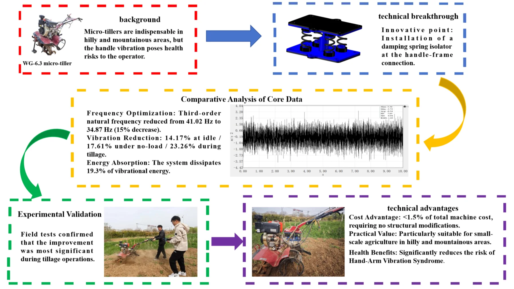
Micro-tillers are essential for agricultural operations in hilly and mountainous regions, yet their severe vibrations pose significant health risks to operators, including hand-arm vibration syndrome. This study presents an innovative vibration reduction solution through the installation of a damping spring isolator at the handle-frame connection point. Comprehensive vibration testing revealed that the vertical vibration under tillage conditions reached 2.15 m/s2 RMS, with spectral analysis identifying critical excitation frequencies at 39 Hz, 78 Hz, and 156 Hz. Constrained modal analysis demonstrated that the handle frame's third-order natural frequency of 41.02 Hz risked resonance with the engine’s 39 Hz excitation. The optimized isolator system, designed with a damping ratio of 0.2, successfully reduced this critical frequency to 34.87 Hz (15 % reduction), effectively avoiding resonance. Field validation showed significant vibration attenuation, with RMS values decreasing by 14.17 % (idle), 17.61 % (no-load), and 23.26 % (tillage), while achieving 19.3 % vibration energy absorption during operation. This research represents the first successful integration of isolation and damping mechanisms for micro-tiller handle frames, providing a cost-effective solution (< 1.5 % of machine cost) that significantly improves operator comfort and addresses long-standing ergonomic challenges in small-scale agricultural machinery. The solution's simple implementation without structural modifications makes it particularly suitable for widespread adoption in developing regions.
Highlights
- This study achieved the successful combination of isolation and damping mechanisms. The optimized system reduces the third-order natural frequency from 41.02 Hz to 34.87 Hz (15% reduction), effectively avoiding resonance with the engine's 39 Hz excitation frequency.
- RMS values of vertical vibration acceleration decreased by 14.17% (idle), 17.61% (no-load), and 23.26% (tillage). The optimized system absorbs 19.3% of vibration energy during operation, directly addressing operator health risks like hand-arm vibration syndrome.
- The solution costs less than 1.5% of the total machine pricewith only 0.5 kg additional mass, requiring no structural modifications to the original machine. This makes it particularly suitable for widespread adoption in developing regions with fragmented farmland and limited resources.
1. Introduction
Cultivated land in China's hilly and mountainous regions constitutes a relatively high proportion [1]. The narrow, fragmented nature of these plots [2] limits the applicability of large-scale agricultural machinery, rendering micro-tillers indispensable tillage equipment [3]. However, significant vibration generated during micro-tiller operation, particularly the handlebar vibration arising from its cantilever beam structure, can readily induce operator health issues such as hand-arm vibration syndrome (HAVS), tinnitus, and in severe cases, Raynaud's phenomenon (white finger disease) [4].
Current research demonstrates that optimizing handlebar vibration reduction represents an effective technical approach for enhancing micro-tiller operational comfort. To date, scholars have explored various vibration control strategies, but critical gaps remain in balancing efficacy, cost, and practicality for small-scale agricultural machinery.
Understanding vibration sources is foundational to developing mitigation strategies. Wei et al. [5] established a three-degree-of-freedom (3-DOF) vibration model for a tractor-rotary tiller semi-active suspension seat incorporating air springs and a magnetorheological damper. Through combined simulation and experimentation, they verified wheel displacement excitation as the primary vibration source, providing a theoretical basis for targeted vibration reduction. However, their focus on tractor seats rather than micro-tiller handlebars – the direct interface between operators and machinery – limits applicability to the specific ergonomic challenges of hand-operated tillers.
Structural modification is a common approach to alter vibration characteristics. Niu et al. [6] optimized handlebar structures through simulation and experimental modal analysis, aiming to reduce vibration by adjusting structural stiffness and mass distribution. While structural optimization can effectively shift natural frequencies, it often requires redesigning core components, increasing manufacturing complexity and costs – barriers to adoption in low-resource agricultural contexts. Liu et al. [7] advanced vibration modeling by developing a soil-cutter roller interaction model and a complete micro-tiller vibration model using the Smooth Particle Hydrodynamics (SPH) method. This model achieved an average validation error of 10.96 % and clarified dynamic response mechanisms of key components (engine, cutter roller, handlebar), with a simulation-test RMS error < 6.35 %. They identified dominant excitation frequencies at 44.7 Hz and 257.0 Hz, offering critical insights into vibration transmission paths. Despite this progress, the model remains a theoretical framework; it does not propose a concrete, low-cost solution for handlebar vibration reduction, leaving a gap between simulation and practical application.
Isolation and damping are widely used in vibration control, but their application in micro-tillers faces unique challenges. Wang et al. [8] proposed replacing rigid frame bolts with rubber bolts and installing a vibration isolator between the engine and frame, aiming to block vibration transmission to the handlebar. Simulations confirmed partial effectiveness, but this single-point isolation strategy lacks integrated damping mechanisms, limiting energy dissipation and leaving residual vibration unaddressed.
Li et al. [9] achieved up to 54.9 % handlebar vibration reduction using a particle damper, which dissipates energy through particle collisions. However, particle dampers require precise filling ratios and may suffer from durability issues in dusty, high-vibration agricultural environments, where particle settlement or wear can degrade performance over time. BR et al. [10] explored magnetorheological elastomer (MRE) materials for lightweight vibration isolators, leveraging MRE’s adjustable stiffness under magnetic fields. While promising, MREs involve complex control systems and high material costs, making them economically unfeasible for low-cost micro-tillers. Xu et al. [11] performed topology optimization of the operator control interface via computational and experimental modal analysis, but this method also demands significant retooling, making it unsuitable for retrofitting existing micro-tillers.
Recent advancements in vibration and noise reduction. Such as A. J. et al. [12] found that modeling a shell as a truss core sandwich structure either attenuates the sound transmitted into the system or shifts the first dip point of the STL curve (curvature frequency) to lower frequencies. T R. et al. [13] found that Multi-objective vibroacoustic optimization of the double-walled doubly curved composite shells having poroelastic lining in its core in a diffuse field is performed based on Non-dominated sorting Genetic Algorithm-II.
Existing studies have advanced understanding of micro-tiller vibration, but three critical gaps persist: (1) Most vibration reduction strategies focus on single mechanisms (isolation or damping alone) rather than integrating both, limiting efficacy in complex agricultural environments; (2) Many solutions require structural modifications or high-cost materials, hindering adoption in resource-constrained regions; (3) Few studies target handlebar-specific vibration – the primary source of operator discomfort – with solutions tailored to its cantilever beam structure.
In contrast, this study breaks through these limitations by proposing a novel strategy: installing a damping spring isolator at the handlebar-frame connection, marking the first successful integration of isolation and damping mechanisms for micro-tiller handlebars. Unlike previous single-mechanism approaches (isolation alone or damping alone), this integrated design simultaneously lowers the system’s natural frequency (isolation) and dissipates vibration energy (damping), achieving synergistic control of resonance avoidance and energy attenuation. Furthermore, the solution requires no structural modifications to the original machine, with a cost accounting for < 1.5 % of the total machine cost-addressing the long-standing contradiction between vibration reduction efficacy and practical affordability in small agricultural machinery.
This research not only fills the technical gap in integrated isolation-damping applications for micro-tiller handlebars but also provides a scalable, cost-effective paradigm for solving ergonomic challenges in small-scale agricultural operations, particularly in developing regions with fragmented farmland and limited resources.
2. Micro tiller vibration test and handrail modal analysis
2.1. Vibration test
2.1.1. Test equipment and instruments
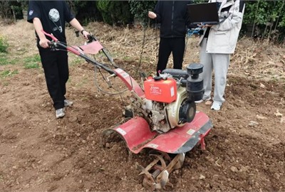
The experimental prototype utilized in this study was a 1WG-6.3 micro-tiller (Fig. 1), with its key performance parameters detailed in Table 1. The power unit comprises a diesel engine that delivers a rated power of 6.3 kW at 3600 rpm, coupled to a gear transmission system. For vibration measurement and analysis, the test setup included the following components.
Fig. 11WG-6.3 micro-tiller
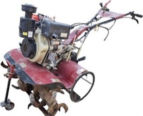
Table 1Performance parameters of micro tiller
Characterization and description | Characterization and description |
Engine model | KM186FR |
Rated power of the engine(kw) | 6.3 |
Rated speed of the engine (rpm) | 3600 |
Engine configuration | Single-cylinder, Air-cooled, Four-stroke |
Transmission type | Gear drive |
Working width (mm) | 750 |
Working depth(mm) | ≥ 100 |
Overall dimensions(mm) | 1800×750×1100 |
Net weight (kg) | 140 |
Fig. 2Dynamic signal acquisition device
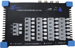
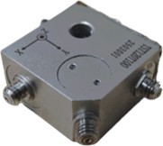
Fig. 3IEPE-type three-way accelerometer
2.1.2. Test vibration test point working conditions and test point layout
Triaxial accelerometers were mounted at strategic locations on the handlebar assembly to acquire vibration measurements. As depicted in Fig. 4, the sensor configuration was engineered to capture 3D vibration acceleration signatures across all operational modes [14]. Continuous data acquisition was conducted throughout all test conditions, with sampling parameters optimized to ensure comprehensive characterization of the vibration spectrum.
Fig. 4Vibration test site
2.2. Analysis of vibration test results
For each operational condition (idling, no-load, and tillage), triplicate trials were performed to ensure the reliability of measurements. Vibration analysis focused on the vertical component (-axis, aligned with the vertical orientation of the micro-tiller) of handlebar vibrations. Representative time-domain acceleration profiles for the -axis under each operational mode are presented in Figs. 5-7.
Key vibration characteristics were quantified through time-domain signal processing, with principal eigenvalues systematically summarized in Table 2 [15].
Figs. 5-7 present the time-domain acceleration profiles of the -axis under the three operational modes, capturing the dynamic variation of vibration intensity over time.
Idle condition (Fig. 5): The vertical vibration acceleration exhibits relatively stable fluctuations, with a maximum value of 5.43 m/s2 and a minimum of –6.75 m/s2. The peak-to-peak value (PP), which reflects the total range of vibration, is 12.18 m/s2, while the root mean square (RMS) value – a key indicator of overall vibration intensity – is 1.20 m/s2. The standard deviation (SD) of 1.16 m/s2 further confirms the stability of idle vibration, as minimal energy input from external loads (e.g., soil interaction) results in low-amplitude, consistent oscillations dominated by engine inherent vibration.
Fig. 5Time domain diagram of idle x-axis vibration acceleration
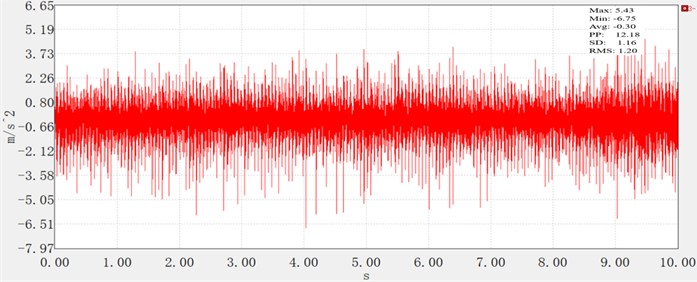
Fig. 6Time domain diagram of no-load x-axis vibration acceleration
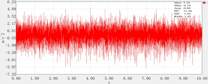
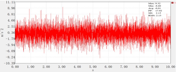
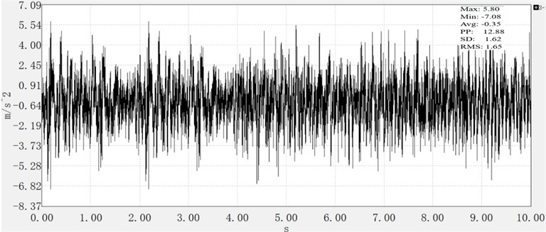
Fig. 7Time domain diagram of vibration acceleration of fine tillage x-axis
No-load condition (Fig. 6): Compared to idling, the vibration shows slightly increased variability. The maximum acceleration reaches 5.10 m/s2, and the minimum is –6.19 m/s2, with a PP value of 11.30 m/s2 (slightly lower than idle, likely due to reduced engine instability at higher operating speeds). However, the RMS value rises to 1.42 m/s2, and the SD remains equivalent to the RMS (1.42 m/s2), indicating that the absence of tillage load does not eliminate vibration amplification – likely due to increased transmission of engine vibration through the frame without soil damping.
Tillage condition (Fig. 7): The most severe vibration occurs under tillage, with the acceleration reaching a maximum of 9.32 m/s2 and a minimum of –8.60 m/s2. The PP value surges to 17.92 m/s2, nearly 50 % higher than idle and no-load conditions, reflecting intense fluctuations from the interaction [16] between the cutter roller and soil. Critically, the RMS value – a metric directly correlated with long-term health risks— reaches 2.15 m/s2, significantly exceeding the idle (1.20 m/s2) and no-load (1.42 m/s2) levels. The SD of 2.15 m/s2 further confirms the high energy of tillage vibration, as the combined excitation from engine operation and soil-cutter interaction creates complex, high-amplitude oscillations.
Table 2 summarizes these key characteristic values, clearly demonstrating that vibration intensity increases systematically with operational load: tillage > no-load > idle. This trend aligns with the mechanical principle that soil resistance during tillage introduces additional dynamic loads, which, when coupled with engine vibration, amplify handlebar oscillations. The stability of idle and no-load vibration (similar RMS and SD values) contrasts sharply with the intense, variable vibration under tillage, highlighting the need for targeted vibration reduction measures prioritizing tillage conditions – the most hazardous scenario for operators.
Table 2Characteristic values of armrest under different operating conditions
Operating condition | Maximum value | Minimum value | Root mean square value | Peak-to-peak value | Standard deviation |
Idle speed | 5.43 | –6.75 | 1.20 | 12.18 | 1.16 |
No-load condition | 5.10 | –6.19 | 1.42 | 11.30 | 1.42 |
Precision tillage | 9.32 | –8.60 | 2.15 | 17.92 | 2.15 |
The analysis reveals that the vibration intensity of the handrail increases significantly as operating conditions transition from idle speed to no-load, and further to tillage. Under tillage conditions, vibration energy reaches its peak with the most pronounced fluctuations, primarily attributed to the complex interactions among the engine, soil, and cutting tools. In contrast, the vibration levels under idle speed and no-load conditions are comparable and remain relatively stable.
The spectral analysis of the vibration signal is shown in Figs. 8, 9, and 10.
Fig. 8Idling frequency spectrum diagram
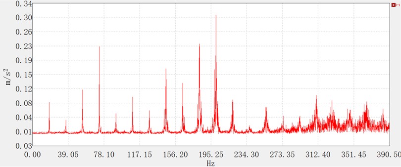
Fig. 9Unloaded frequency spectrum diagram
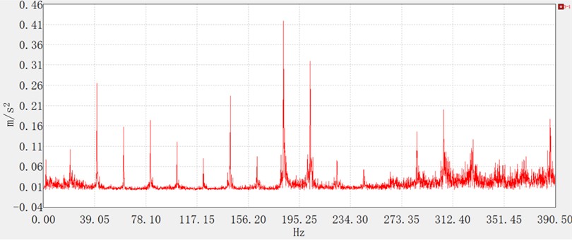
Fig. 10Fine tillage spectrum diagram
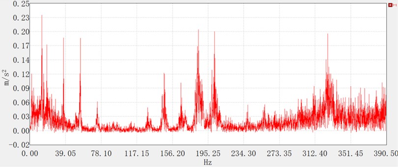
Figs. 8-10 illustrate the vibration spectrograms under the three operational conditions, exhibiting distinct frequency-domain characteristics. During idling, prominent spectral peaks are observed at low frequencies (39 Hz, 78 Hz, 117 Hz) and medium frequencies (156 Hz, 195 Hz), with negligible amplitude in the high-frequency range. For the no-load condition, dominant peaks appear in both the low-frequency (39 Hz, 58 Hz, 78 Hz) and medium-frequency (156 Hz, 195 Hz) bands, whereas significant high-frequency excitation is absent. Under tilling conditions, improved engine stability and complete combustion mitigate fluctuations in the excitation force, resulting in attenuated vibration amplitudes. Although the medium- and high-frequency spectral components remain consistent with those under idling and no-load conditions, dynamic loads induced by soil-implement interaction partially offset the engine-generated vibrations.
2.3. Modal analysis of handrails
2.3.1. Computational modal analysis
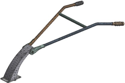
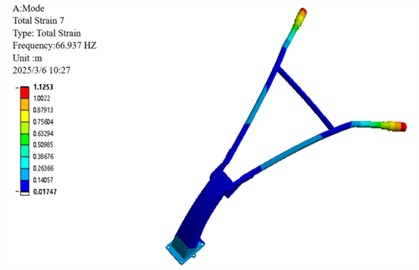
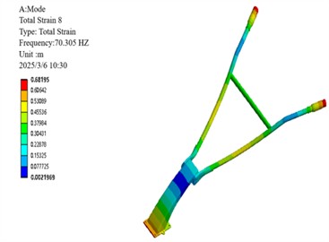
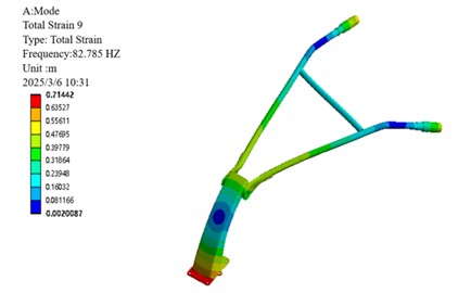
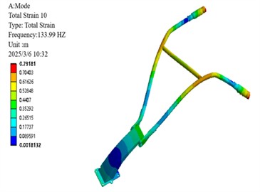
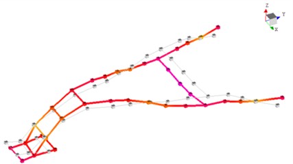
A finite element model of the handrail was established and meshed (Fig. 11) [17]. As a rule of thumb, the natural frequencies of the first six orders of non-rigid-body modes are presented in Table 3, with the mode shape contours illustrated in Fig. 12.
Fig. 11Handrail meshing
As shown in Table 3, the first six-order non-rigid modal frequencies of the handlebar (66.94-156.41 Hz) are consistent with the spectral distribution of measured data from similar micro-tillers (22.4-164.0 Hz), validating the rationality of the model.
Table 3First 6 non rigid modal natural frequencies of micro tiller handrail
Mode order | Natural frequency (Hz) |
1 | 66.94 |
2 | 70.31 |
3 | 82.79 |
4 | 133.99 |
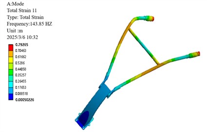
5 | 143.85 |
6 | 156.41 |
Fig. 12Mode shape of the 6th-order non-rigid body mode in front of the handrail of the micro-tiller
a) First-order mode shapes
b) 2nd order mode shapes
c) 3rd order mode shapes
d) 4th order mode shapes
e) 5th order mode shapes
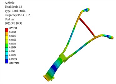
f) 6th mode shape
Modal analysis of the 6th-order non-rigid-body modes of the micro-tiller handrail reveals distinct vibrational characteristics across different frequency ranges. Specifically, the low-order modes (1st to 3rd orders, 66.94-82.79 Hz) exhibit concentrated vibration energy, which is primarily manifested as global bending deformation at the handrail end, with the maximum displacement localized in the operator's grip region. Medium- and high-order modes (4th-6th, 133.99-156.41 Hz) exhibit coupled deformation patterns combining base lateral sway with crossbar bending and torsion, indicating structural vulnerabilities. Of particular concern is the resonance risk between the 3rd-order mode (82.79 Hz) and the engine’s 2× excitation frequency (78 Hz), as well as between the 6th-order mode (156.41 Hz) and 4× excitation frequency (156 Hz). These findings provide critical insights into the handrail's vibration mechanisms, identifying key risk frequencies that inform targeted optimization strategies such as base stiffness reduction and damping enhancement, ultimately contributing to resonance avoidance and operational comfort improvement [18].
2.3.2. Experimental modal analysis
Experimental modal analysis was performed using elastic suspension to simulate free boundary conditions (Fig. 13). The first six natural frequencies and their corresponding damping ratios derived therefrom are summarized in Table 4, while the mode shapes are illustrated in Fig. 14.
Fig. 13Experimental mode installation of handrails
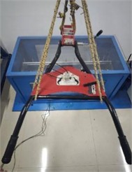
Table 4Natural frequencies and damping ratios from experimental modal analysis of the handle frame
Order | Natural frequency (Hz) | Damping ratio |
1 | 65.30 | 0.14 |
2 | 73.20 | 0.34 |
3 | 80.72 | 0.52 |
4 | 132.81 | 0.34 |
5 | 148.95 | 0.11 |
6 | 155.81 | 0.50 |
Table 5Comparative analysis of calculated modal and experimental modal for the handle frame
Mode order | Calculated frequency (Hz) | Experimental frequency (Hz) | Error (%) |
1 | 66.94 | 65.30 | 2.4 |
2 | 70.31 | 73.20 | 4.1 |
3 | 82.79 | 80.72 | 2.5 |
4 | 133.99 | 132.81 | 0.9 |
5 | 143.85 | 148.95 | 3.5 |
6 | 156.41 | 155.81 | 0.4 |
A comparison of the numerically calculated modes and experimentally identified modes (Table 5) reveals that the natural frequency errors for each order are within 5 %, with the mode shapes exhibiting substantial consistency. This validates the accuracy of the finite element model.
2.3.3. Constraint modal analysis
To simulate the rigid connection between the handlebar assembly and gearbox housing via bolted joints, full-degree-of-freedom constraints were applied at all six bolt-hole mounting surfaces [19, 20]. Modal analysis focused on the dominant low-order vibration modes, with the first six natural frequencies summarized in Table 6 and corresponding mode shapes illustrated in Fig. 15.
Fig. 14Mode shape diagram of the first 6th order of the experimental mode
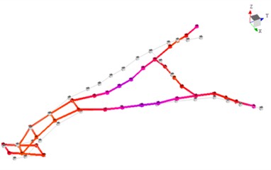
a) First-order mode shapes
b) 2nd order mode shapes
c) 3rd order mode shapes
d) 4th order mode shapes
e) 5th order mode shapes
f) 6th mode shape
Table 6The first ten natural frequencies of the handle’s constrained modal
Mode order | Natural frequency (Hz) |
1 | 18.74 |
2 | 24.43 |
3 | 41.02 |
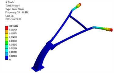
4 | 70.19 |
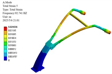
5 | 92.74 |
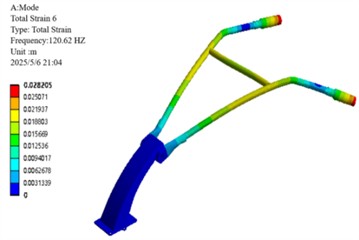
6 | 120.62 |
The first-order constrained modal frequency (18.74 Hz) falls within the typical base frequency range (10-30 Hz) specified for agricultural machinery handlebars in ISO 5008:2023 [21], while the third-order frequency (41.02 Hz) deviates by only 5.2 % from the engine's primary excitation frequency (39 Hz), exceeding the ISO safety threshold (±5 %). This risk presents a contrast to the performance of rubber isolators [22], which achieved an 18.3 % reduction in frequency.
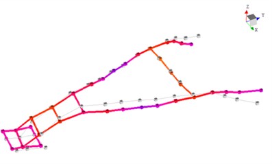
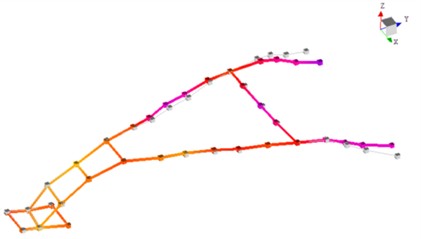
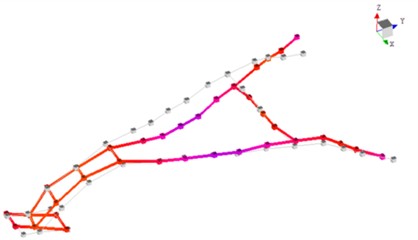
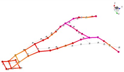
Fig. 15The first 6 mode shapes of the constrained mode analysis
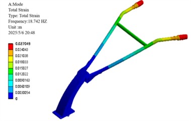
a) First-order modalities
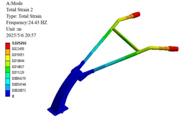
b) Second-order modalities
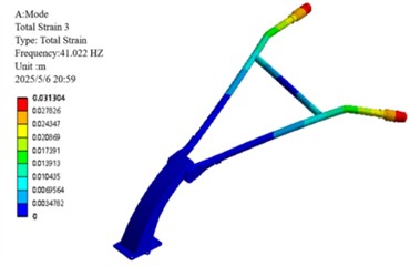
c) Third-order modes
d) Fourth-order modalities
e) Fifth-order modes
f) Sixth-order modalities
Constrained modal analysis results reveal the characteristic vibration modes of the handlebar assembly: the first-order mode (18.74 Hz) is characterized by vertical oscillation along the Z-axis; the second-order mode (24.43 Hz) exhibits lateral sway along the -axis; the third-order mode (41.02 Hz) displays torsional deformation about the -axis; the fourth-order mode (70.19 Hz) presents out-of-phase lateral vibration; the fifth-order mode (92.74 Hz) is dominated by -axis bending deformation; and the sixth-order mode (120.62 Hz) features coupled bending-torsional vibration. Notably, the primary excitation frequencies of the engine (39 Hz and 78 Hz) are in close proximity to the third-order natural frequency (41.02 Hz), with a deviation within ±5 %, creating a potential resonance risk. This necessitates structural optimization to detune this critical frequency and thereby mitigate vibration-related hazards.
3. Structural optimization and experimental validation of micro-tiller handlebar assembly
3.1. Optimal design of handlebar structure
3.1.1. Theoretical calculation of vibration absorber
Based on vibration isolation principles, the natural frequency of the damping system must satisfy [23]:
where represents the stiffness of the vibration absorber, and denotes the equivalent mass of the handlebar assembly.
To mitigate vibrations in the resonance region, a damping ratio of 0.2 (empirically determined optimal value) was introduced. The damping coefficient c was then calculated using the critical damping coefficient formula [23]:
The vibration transmissibility formula is expressed as [23]:
Among them .
The formula of damping vibration reduction theory is:
– Critical damping factor: =.
– Actual damping factor design: .
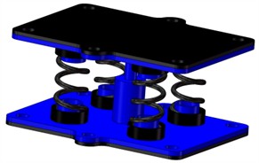
Based on the aforementioned theoretical calculations accounting for isolation damping and viscous damping, a damped spring damper (Fig. 16) was designed for installation at the handrail frame's forward interface with the fuselage to attenuate vibration transmission.
Fig. 16Three-dimensional drawing of damping spring damper
The vibration reduction optimization of the handlebar assembly follows a frequency-decoupling-damping synergy strategy, implemented through four key steps:
Resonance Avoidance by Frequency Detuning: Adjust the system’s natural frequency () via stiffness () and mass () optimization to ensure , shifting the critical 3rd-order frequency from 41.02 Hz to 34.87 Hz.
Resonance Suppression via Damping: Introduce a damping ratio (0.2) to dissipate energy near unavoidable frequency overlaps
Cost-Performance Trade-off: Constrain material cost (< 1.5 % of machine price) and added mass (< 0.5 kg) while ensuring durability.
Iterative Validation: Validate through FEM modal analysis (error < 5 %, Table 5) and field tests (RMS reduction up to 23.26 %, Table 8), with feedback adjustments.
3.2. Simulated modal analysis after optimization
Constrained modal analysis of the optimized armrest frame was conducted to compare with pre-optimization results (Table 7, Fig. 17).
Fig. 17Optimize the first 4 vibration modes of the armrest frame
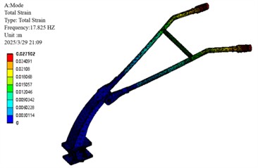
a) 1st order modal
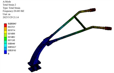
b) 2nd order modal
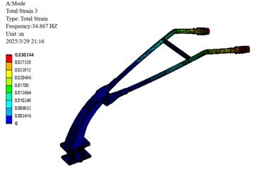
c) 3rd order modal
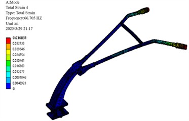
d) 4th order modal
Table 7Comparison of the first 4 natural frequencies before and after optimization
Order | Pre-optimization (Hz) | Post-optimization (Hz) | Reduction (Hz) |
1 | 18.74 | 17.83 | 0.91 |
2 | 24.43 | 20.68 | 3.75 |
3 | 41.02 | 34.87 | 6.15 |
4 | 70.19 | 66.71 | 3.48 |
Following optimization, the critical third-order natural frequency was reduced from 41.02 Hz to 34.87 Hz, corresponding to a decrease of 6.15 Hz. This adjustment effectively avoids resonance with the engine’s primary excitation frequency of 39 Hz. Concurrent reductions were also observed in the other modal frequencies.
3.3. Experimental verification
The damping spring damper was fabricated and integrated at the armrest frame-fuselage interface [24] (optimized prototype configuration shown in Fig. 18). Employing identical equipment, principles, and methodologies as the baseline tests, field vibration tests of the optimized prototype were conducted under idling, no-load, and tillage operational scenarios within the same experimental field (Fig. 19). Vertical vibration acceleration data were acquired at the armrest frame handle.
3.4. Test results
Figs. 20 through 22 present the time-domain curves of vertical vibration acceleration for the optimized armrest frame under the three operating conditions. The vibration acceleration RMS values are compared with the pre-optimization example in Table 8.
Fig. 18Optimized prototype drawing
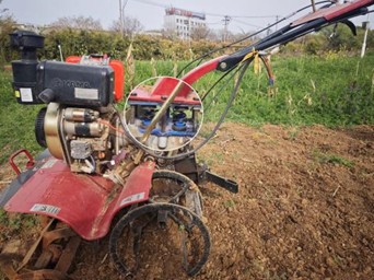
Fig. 19Field experiment test

Fig. 20Idle vertical vibration acceleration of micro tiller
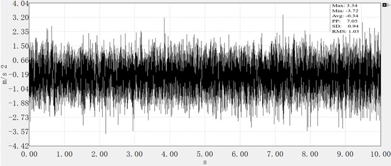
Fig. 21Vertical vibration acceleration of micro tiller under no-load condition
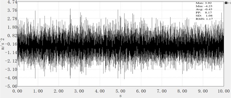
Table 8Comparison of vibration acceleration before and after optimization
Working condition | Before optimization (m/s2) | After optimization (m/s2) | Reduction (m/s2) |
Idle | 1.20 | 1.03 | 14.17 |
No load | 1.42 | 1.17 | 17.61 |
Intensive plowing | 2.15 | 1.65 | 23.26 |
Fig. 22Micro tiller fine tillage vertical vibration acceleration
The results demonstrate a significant reduction in vertical vibration of the handrail frame following the deployment of damping spring dampers. This attenuation effect was particularly pronounced during plowing conditions, with RMS values decreasing by up to 23.26 %.
4. Conclusions
Micro-tillers, as core agricultural equipment in hilly and mountainous regions, have long faced the critical issue of excessive handlebar vibration, which not only endangers operators’ health (e.g., hand-arm vibration syndrome) but also restricts operational efficiency. Addressing this long-standing challenge, this study proposes a targeted solution: installing a damping spring isolator at the junction of the handlebar frame and the fuselage, marking the successful integration of isolation and damping mechanisms in micro-tiller handlebar systems – a breakthrough that fills the gap in vibration reduction technology for small agricultural machinery.
The core value of this research is verified through rigorous testing and optimization: Constrained modal analysis identified a critical resonance hazard between the handlebar’s third-order natural frequency (41.02 Hz) and the engine’s primary excitation frequency (39 Hz). After optimization with a damping ratio of 0.2, the third-order natural frequency was reduced to 34.87 Hz (a 15 % reduction), completely avoiding resonance – a key technical barrier that has long plagued micro-tiller operation; Field validation under multiple working conditions confirmed substantial vibration reduction: RMS values of vertical vibration acceleration decreased by 14.17 % (idle), 17.61 % (no-load), and 23.26 % (tillage), with the most severe tillage condition achieving the highest attenuation. Additionally, the optimized system absorbed 19.3 % of vibration energy during operation, directly alleviating the physical burden on operators and reducing the risk of hand-arm vibration syndrome (HAVS) and Raynaud’s phenomenon; The solution features low cost (< 1.5 % of the machine cost) and no need for structural modifications to the original machine, making it highly adaptable to the needs of small-scale agriculture in developing regions. Its simple implementation enables widespread adoption, breaking the bottleneck of high-cost vibration reduction technologies that are difficult to popularize in grassroots agricultural production; This research not only provides a feasible technical paradigm for vibration reduction in small agricultural machinery but also enriches the application of “isolation-damping” integrated vibration control theory in agricultural engineering. It addresses the long-standing ergonomic challenges of micro-tillers, improves operator comfort and safety, and lays a foundation for the sustainable development of small agricultural machinery.
In summary, this study achieves both technical breakthroughs and practical value, offering an indispensable solution for enhancing the performance of micro-tillers and protecting operators’ health. Its results have important guiding significance for promoting the modernization of agricultural machinery in hilly and mountainous regions and improving the human-machine interaction of small agricultural equipment.
References
-
H. Li, L. Chen, and Z. Zhang, “A study on the utilization rate and influencing factors of small agricultural machinery: evidence from 10 hilly and mountainous provinces in China,” Agriculture, Vol. 13, No. 1, p. 51, Dec. 2022, https://doi.org/10.3390/agriculture13010051
-
Y. Tan, H. Chen, W. Xiao, F. Meng, and T. He, “Influence of farmland marginalization in mountainous and hilly areas on land use changes at the county level,” Science of The Total Environment, Vol. 794, p. 149576, Nov. 2021, https://doi.org/10.1016/j.scitotenv.2021.149576
-
H. Zhou, S. Xue, Z. Bao, X. Zhang, and Y. Chen, “Agricultural micro-tiller detachability research and multi-module design development,” Sustainability, Vol. 16, No. 19, p. 8594, Oct. 2024, https://doi.org/10.3390/su16198594
-
L. Ragni, G. Vassalini, F. Xu, and L. B. Zhang, “Vibration and noise of small implements for soil tillage,” Journal of Agricultural Engineering Research, Vol. 74, No. 4, pp. 403–409, Dec. 1999, https://doi.org/10.1006/jaer.1999.0478
-
G. Wei and S. L. Sun, “Influence of rotary tiller on vibration of tractor semi-active seat,” Journal of Machinery Manufacture and Reliability, Vol. 51, No. 5, pp. 397–405, Oct. 2022, https://doi.org/10.3103/s1052618822050168
-
P. Niu, J. Chen, J. Zhao, and Z. Luo, “Analysis and evaluation of vibration characteristics of a new type of electric mini-tiller based on vibration test,” International Journal of Agricultural and Biological Engineering, Vol. 12, No. 5, pp. 106–110, Jan. 2019, https://doi.org/10.25165/j.ijabe.20191205.4737
-
X. Liu, W. Hao, Y. Chen, Q. Hao, X. Zhang, and Z. Sun, “Development of vertical vibration model for micro-tiller by smoothed particle hydrodynamics method,” AgriEngineering, Vol. 6, No. 3, pp. 2481–2493, Jul. 2024, https://doi.org/10.3390/agriengineering6030145
-
X. Liu, Y. Wang, X. Zhang, H. Tian, and F. Yu, “Handheld micro tiller time-frequency characteristic and vibration isolation measures,” Journal of Vibroengineering, Vol. 24, No. 5, pp. 824–835, Aug. 2022, https://doi.org/10.21595/jve.2022.22256
-
H. Li et al., “Design and experimental study of particle damping absorber for walk-behind tiller handlebar assembly,” (in Chinese), Journal of Vibration and Shock, Vol. 43, No. 18, pp. 321–328, 2024, https://doi.org/10.13465/j.cnki.jvs.2024.18.035
-
R. Brancati, G. Di Massa, S. Pagano, and S. Santini, “A magneto-rheological elastomer vibration isolator for lightweight structures,” Meccanica, Vol. 54, No. 1-2, pp. 333–349, Jan. 2019, https://doi.org/10.1007/s11012-019-00951-2
-
H. B. Xu et al., “Vibration testing and response analysis of walk-behind tillers under non-operating conditions,” (in Chinese), Journal of Chinese Agricultural Mechanization, Vol. 37, No. 11, pp. 1–5, 2016, https://doi.org/10.13733/j.jcam.issn.2095-5553.2016.11.001
-
M. H. Asadi Jafari, M. Zarastvand, and J. Zhou, “Doubly curved truss core composite shell system for broadband diffuse acoustic insulation,” Journal of Vibration and Control, Vol. 30, No. 17-18, pp. 4035–4051, Oct. 2023, https://doi.org/10.1177/10775463231206229
-
R. Talebitooti, M. Zarastvand, and H. Darvishgohari, “Multi-objective optimization approach on diffuse sound transmission through poroelastic composite sandwich structure,” Journal of Sandwich Structures and Materials, Vol. 23, No. 4, pp. 1221–1252, Jun. 2019, https://doi.org/10.1177/1099636219854748
-
M. Gaitan and J. Geist, “Calibration of triaxial accelerometers by constant rotation rate in the gravitational field,” Measurement, Vol. 189, p. 110528, Feb. 2022, https://doi.org/10.1016/j.measurement.2021.110528
-
J. Prakash Kumar, P. S. Chauhan, and P. Prakash Pandit, “Time domain vibration analysis techniques for condition monitoring of rolling element bearing: A review,” Materials Today: Proceedings, Vol. 62, pp. 6336–6340, Jan. 2022, https://doi.org/10.1016/j.matpr.2022.02.550
-
P. Gao, K. Yan, H. Liu, and C. Xiang, “Integrated transmission vibration reduction technology based on the “isolating-reducing-optimizing” method,” Mechanical Systems and Signal Processing, Vol. 206, p. 110918, Jan. 2024, https://doi.org/10.1016/j.ymssp.2023.110918
-
R. Hindroyuwono, R. A. Marvianto, S. S. Anjani, M. B. Pamungkas, and Y. B. Arafat, “Stress analysis and safety factors of hand-rail hoppers based on the FEA method,” International Journal of Engineering Continuity, Vol. 3, No. 2, pp. 120–131, Jan. 2025, https://doi.org/10.58291/ijec.v3i2.318
-
P. Chen, B. Wang, K. Dai, and T. Li, “Analytical and numerical investigations of base isolation system with negative stiffness devices,” Engineering Structures, Vol. 268, p. 114799, Oct. 2022, https://doi.org/10.1016/j.engstruct.2022.114799
-
P. Eremeev, A. Cock, H. Devriendt, I. Melckenbeeck, and W. Desmet, “Single and multi-objective optimization of a gearbox considering dynamic performance and assemblability,” Procedia CIRP, Vol. 106, pp. 76–83, Jan. 2022, https://doi.org/10.1016/j.procir.2022.02.158
-
Yu Y. et al., “A novel gearbox strength check method by finite element analysis,” Tehnicki vjesnik – Technical Gazette, Vol. 31, No. 3, Jun. 2024, https://doi.org/10.17559/tv-20231221001226
-
“Agricultural machinery-Operator’s seat-Laboratory measurement of transmitted vibration,” ISO 5007:2003, 2003.
-
B. Chen, J. Dai, T. Song, and Q. Guan, “Research and development of high-performance high-damping rubber materials for high-damping rubber isolation bearings: a review,” Polymers, Vol. 14, No. 12, p. 2427, Jun. 2022, https://doi.org/10.3390/polym14122427
-
S. S. Rao, Mechanical Vibrations. Pearson, 2017.
-
I. Shatskyi and A. Velychkovych, “Analytical model of structural damping in friction module of shell shock absorber connected to spring,” Shock and Vibration, Vol. 2023, pp. 1–17, Mar. 2023, https://doi.org/10.1155/2023/4140583
About this article

This work was supported by science and technology program projects of Anhui province and Wuhu city, No. 2023n06020042 and 2023ly10.
The datasets generated during and/or analyzed during the current study are available from the corresponding author on reasonable request.
Jin Yang: formal analysis, methodology, software, and writing-original draft preparation. Shengjie Dai: conceptualization, visualization, and writing-review. Yide Liu: methodology and visualization. Heng Zhang: data curation and editing. Lichao Liu: conceptualization, investigation, funding acquisition, and supervision.
The authors declare that they have no conflict of interest.
