Abstract
The dynamics of a platform with processed material when its vibrations are excited by two self-synchronizing vibration exciters is considered. A mathematical model taking into account vibro-impact interaction of the material with the platform when the material moves with possibility of leaving the surface is presented. The influence of the material motion and properties on the vibration exciters self-synchronization and on the platform vibrations is analyzed. It is found that the coefficient of restitution has almost no effect on the frequency ranges of the vibration exciters synchronization but it affects the vibrations of the platform and the material. It is shown that the motion modes of the platform and the material depend significantly on possibility for the material to leave the platform surface.
1. Introduction
One of the problems in creating vibration machines with self-synchronizing vibration exciters is to ensure a given motion of their working element, which is required for the effective implementation of vibration-based materials and parts processing [1-4]. Usually, the design of vibration machines is carried out on the basis of modeling their dynamics, as a result of which their design parameters are determined. In this case, the issues of choosing a mathematical model and its ability to adequately reflect the most significant features of the system dynamics, caused, in particular, by the nonlinearity of the elastic-dissipative properties of structural elements, the nonlinear interaction of the working element with the vibration exciters and the material, are of significant importance.
Many studies are devoted to the issues of modeling and analyzing the behavior of materials under vibration and the dynamics of vibration machines with self-synchronizing vibration exciters. Practically important effects arising in various media and materials under vibration, such as vibration displacement, vibration hardening, vibration separation, and vibration injection of gas into liquid, etc., as well as their mathematical models are presented, e.g., in [1-3, 5]. In [1, 2] a general theory of dynamic systems synchronization is presented, and problems of unbalance vibration exciters self-synchronization in various oscillatory systems with linear elastic links are considered. The issues of designing vibration machines with self-synchronizing vibration exciters were considered in [5, 6]. The influence of nonlinearity of elastic links on self-synchronization of vibration exciters was studied in [7, 8]. In [9-11] methods for ensuring the required synchronous rotation of unbalance vibration exciters due to separate control of their power supply are considered.
At the same time, relatively few studies take into account the influence of the processed material and parts motion on the oscillations of the vibration machines working element [12-14]. In most practical calculations, this influence is neglected [3, 11], justifying it by a significantly smaller mass of the material compared to the mass of the working element, the choice of vibration excitation modes far from resonance and a significant power reserve of vibration exciters. In some cases, it is taken into account in the form of equivalent viscous friction forces proportional to the material mass [5], which do not reflect the real nature of forces of interaction with the working element. The use of such approaches allows to significantly simplify the calculations but leads to incorrect results with an increase in the material mass and the vibrations intensity, particularly, when vibration machines are tuned for more energy-efficient resonant operating modes.
As the results of recent experimental studies have shown, the physical and mechanical properties of the processed material can have a significant effect on the dynamics of a vibration machine with self-synchronizing vibration exciters [15]. Thus, in particular, when processing granular material (in the form of metal rollers), a noticeable decrease in the amplitudes of the working element vibrations is observed compared with the amplitudes when a solid body of the same mass is fixed to the working element. It was also shown that the use of an additional elastic vibration limiter leads to an expansion of the frequency range in which synchronous rotation of vibration exciters with a mutual phase close to zero is ensured.
From the point of view of modeling and analysis of the influence of damping on dynamic processes occurring in mechanical systems, the review [16] is of interest, which examines in detail the issues of modeling methodology, key factors, design optimization methods, and approaches to experimental testing. In addition, the technical capabilities of the so-called tuned particle damper are systematically analyzed, the use of which has demonstrated its effectiveness for various technical applications. In [17] an analysis of the conditions for the transfer of vibration energy within a dynamic system with two degrees of freedom (translational and angular) from one partial system to another is given. Similar situations arise in autoparametric systems, and in this work this effect is used to excite electromotive force in solenoid coils, where damping plays a significant role.
This article considers technological processes in which the processed material, located on a vibrating platform, can leave its surface. The platform vibrations are excited by two self-synchronizing unbalance vibration exciters, implementing a unidirectional periodic excitation when they rotate in opposite directions.
The main objective of the work is to assess how accounting for the possibility of the material to leave the platform surface and their subsequent vibro-impact interaction (hereinafter, the impact model) influences the excited platform vibrations, the material motion and the vibration exciters synchronization depending on the excitation frequency and the contact interaction properties.
2. Mathematical model
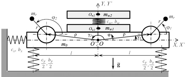
The calculation model of the vibrating platform (Fig. 1) is a solid body with two unbalance vibration exciters rigidly fixed to it, which the rotation excites the platform vibrations in the plane. The platform with vibration exciters has a mass and a moment of inertia relative to the common center of mass at point . The platform is installed on a fixed base using linear-elastic elements with stiffness and damping , located symmetrically at a distance from the vertical axis . The platform compliance in the direction is constrained by an elastic element with stiffness and damping . The vibration exciters are located symmetrically relative to axis at an equal distance from the system center of mass. The platform vibrations are described by displacements and of its center of mass along the corresponding coordinate axes and by an angle of rotation , measured from the horizontal axis counterclockwise, relative to its static equilibrium position. The vibration exciters have the same imbalances and are driven by almost identical induction motors. The motors torque characteristics are described by the Kloss formula [3, 14]:
where 1, 2 is the vibration exciter number, and are the critical torque and slip of the -th motor, respectively, is the slip of the -th motor, is the synchronous rotational speed of the -th motor, P is the number of pole pairs of the motor, , where is the frequency of the supply voltage, is the coefficient, taking into account the direction of the -th motor torque ( corresponds to the action of the motor torque counterclockwise). The vibration exciters rotate in opposite directions. It is important to note that both electric motors are powered from a common AC source, the frequency of which will determine both the angular velocity of the imbalances and, accordingly, the disturbing forces, and the movement (forced vibrations) of the entire system. Thus, the power frequency of the vibration exciters is the control parameter for the system under consideration.
Fig. 1Vibrating platform model
The calculation scheme under consideration describes the processes of movement and interaction of granular material and parts (hereinafter, the material) with a vibrating working element of vibration machines, where the material is processed under unidirectional vertical vibration. Such disturbance is used, for example, for vibro-impact hardening of structural materials, for vibration compaction of bulk materials, for vibro-abrasive processing of parts, etc. The resulting vibration movement of the processed material consists of movements of each individual particle. This movement is characterized by a complex nature and a significant number of contact interactions, both of the material particles with the vibration platform surface, and among themselves. Taking these interactions into account requires building rather complex models and performing resource-intensive calculations [18, 19]. To achieve the goal of this work, it seems rational to use a material model consisting of two parts (hereinafter, the layers). One layer describes the movement of a material part relative to the vibration platform and takes into account the forces of contact interaction with its surface, the other layer takes into account the influence of contact interaction between the material particles that occurs during their relative movement in the vertical direction. Note that similar material models, in a slightly different form, are used, for example, when solving problems of vibration compaction and vibration screening [2, 3].
Thus, the processed material is modeled by a system of two bodies: the lower one with mass , modeling the layer of material in contact with the platform, and the upper one with mass , modeling the remaining part of the material. Both bodies are connected to each other by a linear viscoelastic element with stiffness coefficient and damping coefficient , characterizing the elastic-dissipative properties of the material during the relative motion of its particles. The ratio between the masses of the material layers and the values of and can be determined both experimentally and computationally. In the latter case, the modulus of elasticity of the material can be used as . In this case, the value should be subcritical in order to maintain the conditions of force interaction, but to exclude the occurrence of intensive relative vibrations of the material particles. The motion of the material is described relative to the moving coordinate system , attached to the platform, which coincides with the coordinate system in the undeformed state of the system. Under the action of the platform vertical vibration, vertical movement of particles in the lower material layer occurs, and accordingly, between the material particles and the vibration platform, predominantly normal contact forces of interaction arise, which affect the dynamic behavior of the vibration machine [5]. Taking this into account, in the model it is assumed that the material layers can move relative to the platform only along the normal to its surface, i.e., along the axis, and friction between the material and the platform surface can be neglected. Then the motion of the material relative to the platform is described by the displacement of the lower body center of mass (point in Fig. 1) relative to initial position upon contact with the platform and the displacement of the upper body center of mass at point (point ) relative to the lower body (point ). The considered model of the system allows one to take into account both modes of the material motion: without leaving and with leaving the platform surface, as well as the mutual influence of the movements of the platform, the material and the vibration exciters. Note also that when processing a relatively thin layer of material, which thickness is commensurable with the characteristic particle size, the model can be significantly simplified and presented by only one layer.
The motion of the system under consideration, assuming that the platform rotation angle is small, is described by a system of differential equations, including:
1) Equations of the vibration platform motion:
where , , , , , ;
2) Equations of the vibration exciters rotation:
where , is the moment of inertia of the drive motor shaft, is the moment of resistance to rotation of the -th electric motor, proportional to the centrifugal force of inertia during the unbalances rotation;
3) Equations of the material motion:
where is the normal contact force of interaction between the material and the platform.
Thus, the complete system of equations consists of 7 equations for 7 unknown motion parameters , , , , , , and for the unknown normal contact force . To close the system Eqs. (2-4), two different modes of the material motion are taken into account: the attached to the platform mode and the detached one.
The attached mode is determined by the conditions of the existence of contact between the lower layer and the platform surface:
Then from Eq. (4):
The attached mode motions are determined by the joint solution of system Eq. (2), (3) and (6) with varying frequency of the supply voltage.
At 0 the contact between the material and the platform is lost and the further motion mode is determined by the value of at the next moment in time: if takes positive values, the attached motion mode continues, and if takes negative values, the material leaves the platform surface and its free-flight begins.
In the free-flight phase, the motion of the material and the platform is described by the same Eqs. (2-4) provided that 0. The end of the free-flight phase is determined by the condition of collision of the material with the platform, i.e., . At the moment of collision, the material interaction with the platform is modeled by a direct central impact, as a result of which the velocities of the material and the platform moving elements instantly change, the values of which after the impact are determined as follows:
where the superscripts – and + denote the values of velocities before and after the impact, respectively, , , , is the coefficient of restitution. The subsequent mode of the system motion is determined based on the values of material velocity and contact force found after the impact. Note that the assumption of a direct central impact adopted in this model is due to the above-mentioned features of the platform vibration modes and the material under consideration.
3. Simulation results and their analysis
In the considered problem statement it is assumed that for processing the material the platform should perform vertical oscillations, requiring excitation by a unidirectional vertical periodic force. Such excitation is realized with synchronous rotation of vibration exciters with a phase difference of (hereinafter, synchronous-antiphase rotation). Note that in the considered system, due to vibration exciters self-synchronization, their stable synchronous rotation with a phase difference different from is possible. In this case, the platform vibrations different from strictly vertical ones could be excited. Therefore, when modeling the system motion and analyzing the results, the main attention is paid to the ranges of vibration exciter rotation frequencies, in which their synchronous-antiphase rotation is realized.
Eqs. (1-7) were solved numerically with the following values of the system parameters: 12.42 kg, 0.045 kg, 0.11 kg∙m2, 0.8∙10-3 kg∙m2, 0., 0.09 m, 0.128 m, 22,5°, 157,5°, 580 kN/m, 470 kN/m, 1.8 kN∙m/rad, 300 N∙s/m, 40 N∙s/m, 0.77 N∙s2/m, 9.81 m/s2, 1.2 N∙m, 0.15, 2. The selected values of the vibration platform parameters correspond to the parameters of the test rig presented in [15]. To obtain the frequency characteristics, the calculations were carried out with a gradual change in the power supply frequency of the vibration exciters motors with a step of 0.5 Hz for different ratios of the material and the platform masses () in the range of , and values of the coefficient of restitution in the range of . To assess the influence of the material motion on the excited vibrations of the platform, the obtained results were compared with the calculation results obtained using a model in which the interaction with the material is taken into account by the equivalent viscous friction forces proportional to the material mass, not taking into account the detached motion of the material (hereinafter, the non-impact model) [5].
Fig. 2Simulation results at μw=0
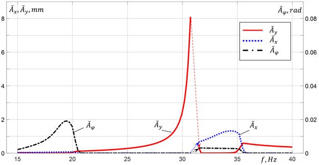
a) RMS amplitudes of the platform vibration
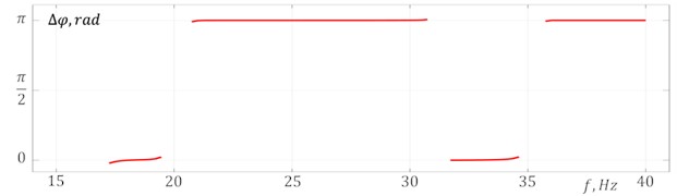
b) Phase difference of the vibration exciters rotation
Fig. 2 shows the root-mean-square values (RMS) of the platform vibration amplitudes in the vertical , horizontal and angular directions (Fig. 2(a)), and the phase difference of the vibration exciters rotation (Fig. 2(b)) at their steady-state synchronous rotation, depending on the excitation frequency (frequency of the vibration exciters synchronous rotation) in the absence of material on the platform (). One can see that the required modes of synchronous-antiphase rotation of the vibration exciters are realized in the frequency range of 21-31 Hz between the first and second resonant frequencies of the system (inter-resonant frequency range), and at frequencies higher than 35.5 Hz above the third resonant frequency of the system (over-resonant frequency range). In these frequency ranges, practically unidirectional vertical harmonic oscillations of the platform are excited. Approaching the second resonance frequency, an increase in the deviation of the values from is observed, caused by an increase in the impact of platform oscillations on the vibration exciters rotation due to the growth of oscillation amplitudes and, accordingly, the energy dissipated in the system. In this case horizontal and angular oscillations of the platform are also excited. The transition through the second resonance of the system is accompanied by an abrupt change in the vibration exciters rotation frequency, as well as an abrupt change in the phase , the system oscillations amplitudes and shape (the corresponding jumps are shown by arrows in Fig. 2(a)). In the frequency range of 31.5-34.5 Hz, located between the second and third resonance frequencies, synchronous-in-phase rotation of the vibration exciters with is settled, at which mainly horizontal and angular oscillations of the platform are excited.
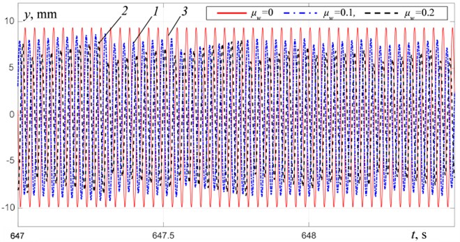
Fig. 3 shows the results of modeling the oscillations of the platform with the material at taking into account the completely inelastic collision between the material and the platform 0. The platform vibrations and the material motion at for three different distinctive excitation modes – in the inter-resonant frequency range at a distance from the second resonant frequency at 25.75 Hz and near this resonant frequency at 30.7 Hz, and in the over-resonant frequency range at 38.75 Hz are shown in Figs. 4-5. It is evident (Fig. 3(b)) that with an increase in the material mass up to , the boundaries of the frequency ranges of vibration exciters synchronous rotation with remain practically unchanged. In the frequency range of 21-27.5 Hz (Fig. 4(a)), an increase in the material mass leads to an increase in the platform oscillation amplitudes; the oscillations character remains practically unchanged and remains close to harmonic with a period equal to period of excitation. Fig. 5 shows the material motion relative to the platform. One can see that the material motion is periodic with a period equal to the period of excitation. The attached mode motion is observed in the frequency range of 21-24.5 Hz at 0.1 and 21-24 Hz at 0.2. At excitation frequencies above 24.5 Hz, the material motion consists of alternating the phases of attached mode motion and the phases of free-flight (Fig. 5(a)). In the presented graphs, the attached mode motion phases correspond to the periods of time when 0. The free-flight phases correspond to the periods of time when 0.
Fig. 3Simulation results at R= 0: 1 – μw= 0.1, 2 – μw= 0.2, 3 – μw= 0
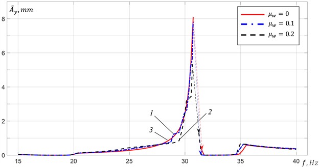
a) RMS amplitudes of vertical vibration of the platform
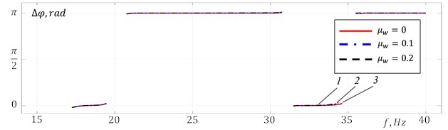
b) Phase difference of the vibration exciters rotation
Fig. 4Platform vertical vibration at R= 0: 1 – μw= 0.1, 2 – μw= 0.2, 3 – μw= 0
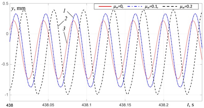
a) At 25.75 Hz
b) At 30.7 Hz
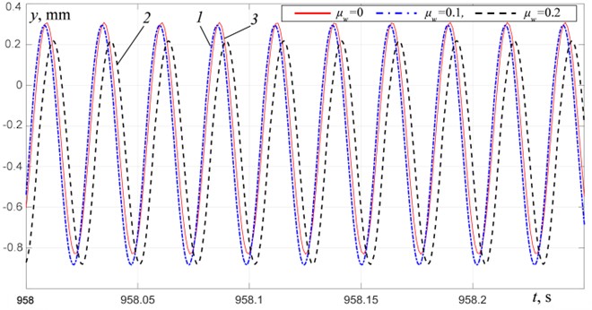
c) At 38.75 Hz
In the frequency ranges 27.5-31 Hz and above 35.5 Hz, the platform oscillation amplitudes decrease with an increase in the material mass (Figs. 4(b)-4(c)). In the frequency range of 29.5-31 Hz, non-periodic oscillations of the platform (Fig. 4(b)) and the material (Fig. 5(b)) are observed. It is apparently associated with an increase in the amplitudes of the material tossing and the duration of its free-flight phase, and, accordingly, an increase in the intensity of collisions between the material and the platform. In the over-resonant frequency range, as we move away from the third resonant frequency, periodic oscillations of the platform close to harmonic (Fig. 4(c)) and periodic modes of material motion (Fig. 5(c)) with the same period equal to the excitation period are settled.
Fig. 5Material motion relative to the platform at R= 0: 1 – μw= 0.1, 2 – μw= 0.2
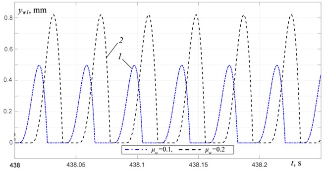
a) At 25.75 Hz
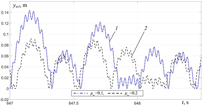
b) At 30.7 Hz
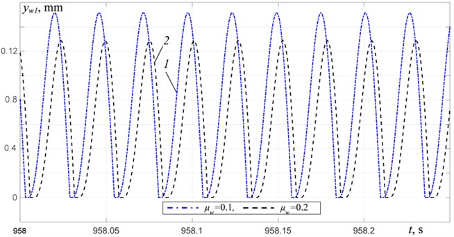
c) At 38.75 Hz
Fig. 6 presents the simulation results for obtained using the non-impact model and the impact model for [0, 0.3, 0.5]. The platform oscillations excited in the inter-resonant frequency range at a distance from the resonant frequency at 25.75 Hz and 28.75 Hz, and near the resonant frequency at 30.7 Hz, as well as in the over-resonant frequency range at 38.75 Hz are shown in Fig. 7. To compare the results, the parameters of the equivalent viscous friction in the non-impact model were selected based on the equality of the root-mean-square values of the amplitudes of the platform vertical oscillations excited in the compared models at the same frequency near the second resonance (at 30.9 Hz).
A comparison of the results for different values of in the range of shows that increasing R does not significantly change the frequency range boundaries of vibration exciters synchronous rotation with . However, changing R affects the vibrations of the platform and the material. When R changes in the range of values in the frequency range of 29-31 Hz, a relatively small increase in the platform oscillation amplitudes (within 5 %) is observed, while in the over-resonant frequency range, a decrease (within 5 %) is observed. In the frequency range of 21-29 Hz, almost no change in the oscillation amplitudes is observed. The change in the character of platform oscillations and material movement depending on the excitation frequency practically corresponds to that obtained at 0. In the inter-resonant frequency range at , an increase in leads to a decrease in the excitation frequency at which non-periodic vibrations of the platform and the material occur. Thus, at 1, non-periodic modes occur at excitation frequencies above 26 Hz. Note that in the frequency range of 21-26 Hz, the amplitudes and character of the vibrations of both the platform and the material do not depend on . In the over-resonant frequency range, an increase in in the range of leads to an increase in the excitation frequency, starting from which periodic vibrations of the platform and the material are settled with a period equal to the excitation period.
Fig. 6RMS amplitudes of vertical vibration of the platform at μw= 0.2: 1 – impact model at R= 0, 2 – impact model at R= 0.3, 3 – impact model at R= 0.5, 4 – non-impact model
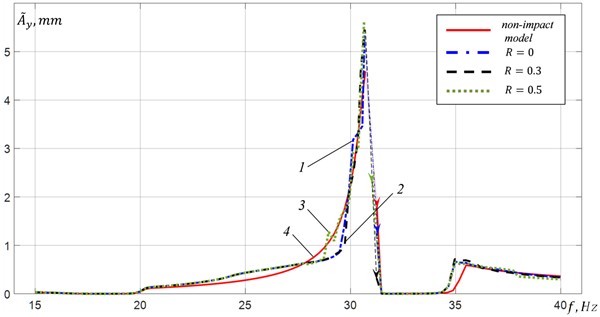
A comparison of the results obtained using the non-impact model and the impact model shows that when oscillations are excited at the same frequencies, the amplitudes and the shapes of the oscillations, determined with and without taking into account the collisions of the platform with the material, can differ significantly. In the inter-resonant and over-resonant frequency ranges at a distance from resonance, this difference appears in the values of the platform oscillations amplitudes. Moreover, in the inter-resonant range there are two frequency regions: 21-26 Hz, in which the oscillation amplitudes for the impact model are greater than those for the non-impact model (Fig. 7(a)), and 26-29 Hz, in which (Fig. 7(b)). In the over-resonant frequency range at a distance from resonance, (Fig. 7(d)), and with an increase in the ratio rises up. In the inter-resonant frequency range near the second resonant frequency, significant differences are observed both in the amplitudes and in the platform oscillations shape (Fig. 7(c)).
Fig. 7Platform vertical vibrations at μw= 0.2: 1 – impact model at R= 0, 2 – impact model at R= 0.3, 3 – impact model at R= 0.5, 4 – non-impact model
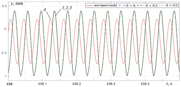
a) At 25.75 Hz
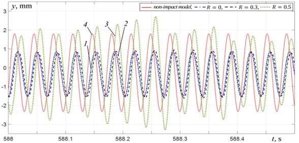
b) At 28.75 Hz
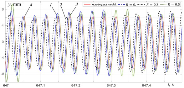
c) At 30.7 Hz
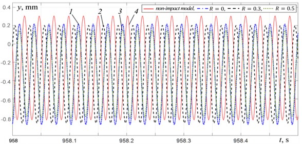
d) At 38.75 Hz
4. Conclusions
The results obtained in this work are in good agreement with the experimental results obtained on the test rig [15]. An increase in the material mass leads to a decrease in the platform vibration amplitudes in the frequency ranges of the vibration exciters synchronous rotation. At the same time, a slight leftward shift of the exciting frequency at which a jump into the over-resonant frequency range occurs is observed (Fig. 3). The transition through resonance is accompanied by an abrupt change in the rotation speeds of the vibration exciters and the mutual phase of their rotation, the values of which are established near corresponding to the synchronous-antiphase rotation mode, which is also observed in the experiments [15].
The performed analysis shows that taking into account or neglecting the possibility of the material to leave the vibration platform surface can lead to significant differences in the motion modes of both the platform and the material, determined at the same excitation frequencies. Thus, in particular, the occurrence of non-periodic oscillations of the platform and the material can affect the vibration processing efficiency. These differences become stronger with an increase in the processed material mass and the vibrations intensity, and are more pronounced when vibrations are excited at near-resonant frequencies. It is shown that the coefficient of restitution, with values of , has no significant effect either on the vibrations of the platform and material (the relative change in amplitudes does not exceed 5 %) or on the frequency range of vibration exciters synchronization. Increasing changes the frequency ranges boundaries in which periodic and non-periodic modes of oscillations of the platform and material are excited: in the inter-resonant frequency range the boundary frequency decreases, while in the over-resonant range it increases. Furthermore, it was found that in the frequency range of 21-26 Hz, the vibration amplitudes and shapes of both the platform and the material do not depend on . It should be noted that in the considered model, the value of characterizes the collision properties of the processed material layer with the platform, rather than its individual particles, and depends significantly on the material layer height. This must be taken into account when choosing the modeling parameters [20]. When modeling a processed material whose layer height is commensurate with the characteristic dimensions of its particles (grains), the values determined for pairs of colliding materials from standard experiments, presented, for example, in [21], should be used. When the material layer height significantly exceeds the characteristic sizes of its particles, the values of should be determined from special experiments, which are beyond the scope of this work, and this seems to be a topic for further research. In the absence of experimental data, in a number of cases 0 can assumed with a sufficient degree of accuracy [20, 22]. The discovered features of the vibration platform dynamics, caused by the interaction with the processed material, typical for many processes used in practice for processing granular materials, should be taken into account when studying the vibration technological processes dynamics and selecting rational parameters for vibration machines and their operating modes.
References
-
I. I. Blekhman, Theory of Vibration Processes and Devices. Vibration Mechanics and Vibration Technology. St. Petersburg: Ore and Metals PH, 2013.
-
I. Blekhman, “Selected topics in vibrational mechanics,” in Series on Stability, Vibration and Control of Systems, Series A, World Scientific, 2011, https://doi.org/10.1142/5013
-
E. E. Levendel, Vibration in Technics. Vibration Processes and Machines. Moscow: Mashinostroenie, 1981.
-
A. A. Prikhodko and E. O. Gerasimenko, “Study of the efficiency of heat transfer in a stirred tank with nonuniform movement of the impeller,” Theoretical Foundations of Chemical Engineering, Vol. 57, No. 2, pp. 215–223, Jun. 2023, https://doi.org/10.1134/s0040579523020094
-
L. A. Vaisberg, Design and Calculation of Vibrating Screens. Moscow: Nedra, 1986.
-
P. Fang, W. Zhu, Y. Hou, and D. Xiao, “Dynamic behaviors and double-frequency synchronization analysis of a dynamic vibration absorption system driven by three co-rotating exciters,” Journal of Vibroengineering, Vol. 27, No. 2, pp. 211–232, Mar. 2025, https://doi.org/10.21595/jve.2025.24661
-
N. Zhang, “Self-synchronization characteristics of a class of nonlinear vibration system with asymmetrical hysteresis,” Journal of Low Frequency Noise, Vibration and Active Control, Vol. 39, No. 1, pp. 114–128, Apr. 2019, https://doi.org/10.1177/1461348419839512
-
X. Zhang, B. Wen, and C. Zhao, “Theoretical study on synchronization of two exciters in a nonlinear vibrating system with multiple resonant types,” Nonlinear Dynamics, Vol. 85, No. 1, pp. 141–154, Feb. 2016, https://doi.org/10.1007/s11071-016-2674-8
-
S. Y. Tyagushev, V. Y. Turkin, and B. Shonin, “Jaw crusher antiphase-locked operation stabilization by means of automatic electric drive,” Obogashchenie Rud, No. 2, pp. 38–40, 2011.
-
D. V. Gorlatov, T. A. Sventzitzkaya, O. I. Tokareva, and D. V. Tomchin, “Synchronization control for vibration unit with non-identical rotors when taking into account measurement errors,” Information science and control systems, Vol. 4, No. 82, pp. 130–143, 2024.
-
Z. Wang, J. Wu, Z. Kou, Y. Zhang, and C. Liu, “Dynamic characteristics analysis of a novel vibrating screen based on electromechanical coupling simulation,” Journal of Vibroengineering, Vol. 25, No. 4, pp. 667–682, Jun. 2023, https://doi.org/10.21595/jve.2023.22823
-
R. F. Nagaev and R. R. Karagulov, “Dynamics of a vibration machine taking into account the influence of the processed material,” (in Russian), Problems of Mechanical Engineering and Reliability of Machines, No. 1, pp. 48–51, 2001.
-
Y.-Z. Jiang, K.-F. He, Y.-L. Dong, D.-L. Yang, and W. Sun, “Influence of load weight on dynamic response of vibrating screen,” Shock and Vibration, Vol. 2019, No. 1, Apr. 2019, https://doi.org/10.1155/2019/4232730
-
A. E. Shokhin, G. Y. Panovko, and I. P. Lyan, “Analysis of vibrations for a vibrating jaw crusher when interacting with material,” Obogashchenie Rud, No. 1, pp. 26–31, Feb. 2021, https://doi.org/10.17580/or.2021.01.05
-
G. Y. Panovko and A. E. Shokhin, “Experimental analysis of dynamics of a nonlinear oscillatory system with self-synchronizing vibration exciters when interacting with bulk material,” Journal of Machinery Manufacture and Reliability, Vol. 53, No. 5, pp. 479–488, Sep. 2024, https://doi.org/10.1134/s1052618824700936
-
Y. Zhu, X. Guo, and D. Cao, “Research progress on tuned particle dampers: a review of modeling, energy dissipation mechanisms, and applications,” European Journal of Mechanics – A/Solids, Vol. 113, p. 105720, Sep. 2025, https://doi.org/10.1016/j.euromechsol.2025.105720
-
C. Liu et al., “Synchronization of broadband energy harvesting and vibration mitigation via 1:2 internal resonance,” International Journal of Mechanical Sciences, Vol. 301, p. 110503, Sep. 2025, https://doi.org/10.1016/j.ijmecsci.2025.110503
-
F. Elskamp and H. Kruggel-Emden, “Review and benchmarking of process models for batch screening based on discrete element simulations,” Advanced Powder Technology, Vol. 26, No. 3, pp. 679–697, May 2015, https://doi.org/10.1016/j.apt.2014.11.001
-
O. O. S. Ogunmodimu, A. N. Mainza, I. Govender, and J.-P. Franzidis, “Granular flow dynamics on vibrating screens: A mechanistic study,” Minerals Engineering, Vol. 228, p. 109337, Aug. 2025, https://doi.org/10.1016/j.mineng.2025.109337
-
M. Soldinger, “Transport velocity of a crushed rock material bed on a screen,” Minerals Engineering, Vol. 15, No. 1-2, pp. 7–17, Jan. 2002, https://doi.org/10.1016/s0892-6875(01)00192-3
-
H. Kruggel-Emden, E. Simsek, S. Rickelt, S. Wirtz, and V. Scherer, “Review and extension of normal force models for the Discrete Element Method,” Powder Technology, Vol. 171, No. 3, pp. 157–173, Feb. 2007, https://doi.org/10.1016/j.powtec.2006.10.004
-
T. Dyr and P. Wodzinski, “Model particle velocity on a vibrating surface,” Physicochemical Problems of Mineral Processing, Vol. 36, No. 1, pp. 147–157, 2002.
About this article

This research is funded by the Russian Science Foundation, project No. 24-19-00333, https://rscf.ru/en/project/24-19-00333/.
The datasets generated during and/or analyzed during the current study are available from the corresponding author on reasonable request.
Grigory Panovko: conceptualization, results analysis, writing the paper. Alexander Shokhin: conceptualization, results obtaining and analysis, writing the paper.
The authors declare that they have no conflict of interest.
