Abstract
One of the most important problems of electronic devices is heating. Especially high-performance processors and electronic cards can draw significant power and therefore reach critical temperatures. Heating can lead to functional loss or failure of devices. Sealed systems are used in many areas today. Sealing is defined as not allowing two substances, water and dust, into a closed space. The purpose of our thesis is to design a new cooling system related to the cooling of sealed electronic devices. External flow ventilation will be used as active cooling, and a heatsink structure will be used as passive cooling. Then, the efficiency of this new design will be analyzed using CFD method. By keeping the device at reasonable temperature values, a new design example will be created, especially for cooling sealed structures. Analysis studies have been conducted according to different ventilation channels. As a result of these studies, reference data on how much heat can be drawn by different fin structures will be obtained. These reference data are aimed to provide an approximate cooling capacity estimation in projects where sealing is required. The data obtained as a result of the study are compared and presented in tabular form.
1. Introduction
As electronic components continue to shrink day by day, their functions are increasing. This situation implies a continuous increase in thermal generation. The problem of heating is one of the most critical factors limiting the functionality and processing speed of electronic components today. Therefore, continuous research is being conducted on cooling electronics. These studies either aim to derive new cooling techniques or to make existing cooling systems more efficient or practical.
Thermal management in electronics is the process employed to control and dissipate the heat generated by electronic devices and components. The objective is to efficiently distribute heat within the semiconductor environment. The heat produced by electronic components can lead to performance degradation, shortened lifespan, and even permanent damage. Therefore, effective thermal management is crucial in electronic design and packaging to mitigate these risks [1].
Effective thermal management is a critical aspect in the design and operation of electronic systems, particularly in military and sealed applications where environmental constraints limit heat dissipation options. Numerous studies in the literature have focused on improving cooling performance through various methods, primarily using air as the working fluid.
Demircan [24] explored the challenges associated with cooling military electronic systems. His findings indicated that increasing air velocity in air-cooled systems significantly enhances heat dissipation capacity, highlighting the importance of airflow optimization.
Similarly, Sözbir [2] conducted both experimental and theoretical investigations on forced convection and temperature variations within air channels. The results demonstrated that adequate cooling was achievable and that the cooling performance improved proportionally with air velocity.
Bilge [3] also concentrated on the air cooling of electronics. In his comparative analysis of two systems-one involving conduction and fins, and the other utilizing convective heat transfer – he concluded that the convective system yielded superior cooling performance.
In a related study, Zuo [4] examined heat transfer through convection using an air-operated heat exchanger with fins. His work validated that such a configuration could provide sufficient thermal regulation for electronic components.
Lee [5] investigated the influence of fin quantity in air-cooled systems using thermal fins. The study revealed that increasing the number of fins enhanced cooling efficiency up to a threshold, beyond which the performance started to decline due to increased airflow resistance and diminishing returns.
Further valuable insights into electronic cooling techniques were provided by Wang [6] and Zhang [7], who collectively discussed a range of approaches and technological advancements in this field.
The thermal management of sealed electronic enclosures has also been addressed. Tien Yu [8] compared computational fluid dynamics (CFD) simulations with experimental data for such systems. The CFD method was shown to produce reliable results, with an error margin of less than 10 %, supporting its applicability in enclosure design.
Building on this, Zhang [9] and Bernardoni [10] investigated the cooling of power converters housed within sealed cabinets. Their work confirmed the validity of CFD-based thermal analyses by aligning simulation results with empirical data, underscoring the method’s practicality in sealed system applications.
Today’s electronic systems are characterized by increasing power density and reduced dimensions, which make efficient thermal management essential [11]. Inadequate cooling leads to reduced system efficiency and negatively impacts the lifespan of hardware components [12]. Consequently, research into various cooling strategies has intensified.
For example, nanofluid technology, developed to enhance heat transfer, has been tested across different platforms, including military systems [13]. The synergistic effect of combining nanofluids with impinging jets has also been evaluated both numerically and experimentally, showing promising results [14,15]. In addition, the fundamental thermal properties of these fluids have been investigated in various numerical studies [16]. Passive cooling technologies such as aluminum foam materials have also been experimentally investigated for their thermal performance in electronics [17].
In specific environments like subsea systems, thermoelectric-based solutions gain importance for example, [18] presents a notable application. The study titled [1] sheds light on optimization efforts in air-cooled systems. More advanced solutions, such as [19] and [20], are also part of active cooling strategies. Furthermore, works like [21] and [22] delve into new-generation thermal conduction materials. Lastly, [6-23] provide a comprehensive overview of thermal solutions in high heat flux sectors such as automotive and aerospace.
Thermal management techniques must be applied to prevent overheating and maintain the safe operating temperature range for electronic components. The selection of thermal management methods and materials depends on various factors such as the size, power, and operating temperature of electronic components, as well as the required performance and reliability.
Sealed electronic enclosures are commonly used in applications where equipment needs to operate in harsh or extreme environments, such as industrial control systems, telecommunications equipment, and military systems. Additionally, they are used in applications requiring protection from environmental elements, such as sensitive electronic systems in medical equipment and laboratory tools. The design of sealed electronic chassis typically relies on gaskets, seals, and O-rings to prevent the entry of air and moisture. The chassis can also be filled with a moisture-absorbing substance to prevent corrosion. In some cases, the chassis can be pressurized or vacuum-sealed to provide additional protection against environmental elements.
Sealed electronic devices are widely used in many fields, especially for military purposes. In these devices, stringent environmental conditions are often required along with sealing requirements. Because these environmental conditions require certain durability criteria, this situation limits the cooling systems that can be used. Passive cooling and thermal fins are often attempted to solve the heating problem. However, in cases where this is insufficient, air cooling methods provide a simple and robust solution. In air cooling, however, sealing criteria can only be met to a certain extent with the help of specific filters.
Taking all these factors into account, this study aims to provide an alternative that can ensure both sealing and environmental tests when passive cooling is insufficient, through external air cooling of an electronic cabinet with high thermal generation, such as a processor. This study seeks to address the thermal challenges in cases where passive cooling is insufficient. Within the scope of the study, working will be carried out on a sample model to examine how much the amount of heat transfer can be increased with alternative external flow channels. These channels have different fin numbers and structures. As a result of the study, providing an alternative solution to other projects with similar boundary conditions is also among the objectives. In light of these challenges, this study endeavors to explore an alternative approach to cooling sealed electronic devices with high thermal generation, such as processors, by harnessing external air cooling.
In addition to the aforementioned studies, recent investigations have further enriched the field of electronic cooling. Elshazly et al. [32] analyzed heat sink performance using CFD, providing valuable insights into simulation-based optimization approaches for electronic cooling systems. Complementarily, Hamad and Adham [33] reviewed the applications of nanofluids in modern heat transfer devices, highlighting their potential to enhance cooling efficiency in next-generation electronic systems. Furthermore, Zhang [34] presented a comprehensive overview of advanced cooling technologies for high-power electronic devices, with particular emphasis on the integration of innovative materials and system-level optimization. Together, these works broaden the scope of thermal management research by connecting simulation, nanofluid technology, and emerging cooling strategies.
Recent studies have increasingly focused on advanced cooling and optimization strategies for high-power-density and sealed electronic systems. For example, Bademlioğlu [27] applied CFD-based optimization using Taguchi and ANOVA methods to electronic amplifiers, highlighting the effectiveness of statistical approaches in thermal management. Similarly, Lad et al. [28] explored fin topology optimization for direct liquid cooling in multi-chip power modules, demonstrating the role of geometric optimization in enhancing cooling efficiency. Li [29] reviewed structural optimization methods in liquid-cooled heat sinks, while Raza and Bhushan [30] conducted CFD analyses of micro-channel heat sinks with pin-fin arrays, both emphasizing the importance of structural design in achieving superior heat dissipation. Moreover, Ersoy [31] provided a comprehensive overview of thermal management strategies in aerospace electronics, further underlining the relevance of robust solutions for harsh environments. Complementary perspectives are also provided by additional works such as [32-34], which investigate innovative materials, hybrid cooling techniques, and optimization methodologies for demanding thermal management applications. Collectively, these studies indicate that advanced design optimization and novel thermal management approaches continue to gain importance, forming a solid foundation for the present study.
Unlike many previous studies that either relied solely on passive cooling or examined generic sealed enclosures, this study specifically investigates external airflow channeling with varying fin geometries for processor-level heat sources. The originality lies in evaluating the trade-off between sealing requirements and enhanced cooling through a combined passive-active configuration. This dual perspective provides practical insights for applications where environmental sealing and high power density coexist, such as military and aerospace electronics.
2. Materials and methods
The objective of electronic thermal management is to effectively transfer heat from the semiconductor junction to the surroundings. This involves several key processes:
– Internal heat transfer within the semiconductor component package.
– Heat dissipation to a heat dissipator.
– Heat dissipation from the heat dissipator to the surroundings through the final cooling pathway.
Efficient thermal management along these pathways underscores the importance of comprehending the fundamentals of heat transfer and how the properties of interface materials, along with their basic physical characteristics, influence the heat transfer process. Heat transfer refers to the movement of heat resulting from a temperature disparity. Temperature represents the measure of thermal energy intensity, while heat flow denotes the transmission of thermal energy from one location to another. At the microscopic level, thermal energy correlates with the kinetic energy of molecules. With an increase in material temperature, the thermal agitation of constituent molecules, evident in both linear motion and vibrational modes, becomes more pronounced. Regions with higher molecular kinetic energy naturally transfer this energy to regions with lower kinetic energy. Various factors such as thermal conductivity, specific heat, material density, fluid velocities, fluid viscosities, surface emissions, and others influence the heat transfer between regions at differing temperatures. Heat transfer mechanisms are contingent upon the surrounding environment and are typically classified into conduction, convection, radiation, and practical thermal resistances.
Central to any cooling solution is its heat transfer threshold, denoting the maximum rate at which heat may be generated by a processor while maintaining junction temperature below acceptable thresholds, typically recommended at 85 °C [12]. Among the array of techniques explored are thermosiphons, heat pipes, electro-osmotic pumping, microchannels, impinging jets, thermoelectric coolers, and absorption systems. These techniques span passive and active cooling systems. Passive cooling systems harness capillary or gravitational buoyancy forces to circulate the cooling liquid, while active cooling systems rely on pumps or compressors for augmented cooling capacity and enhanced performance. PCMs, as a form of passive cooling, have emerged as promising techniques for transient electronic cooling applications due to their high latent fusion heat, high specific heat, and controllable temperature stability. Micro-scale cooling systems exhibit effectiveness in cooling electronic devices or components that generate substantial heat. Notably, microchannel-based heat sinks and micro heat pipes demonstrate significantly higher heat transfer performance compared to conventional heat exchangers. Owing to their compact, lightweight nature and superior cooling efficacy, microchannel-based cooling systems have garnered substantial attention from both academia and industry. Liquid cooling with microchannels stands out as a promising, high-performance cooling technology for compact electronic devices emitting high heat, offering not only significant reduction in package size but also integration potential onto the chip. Heat pipe-based electronic cooling has witnessed widespread adoption and garnered considerable attention from researchers and industries alike. This approach finds application in various electronic devices, with air cooling emerging as a prevalent method for cooling electronics. Air cooling operates by ensuring that the object to be cooled either possesses a relatively larger surface area or experiences increased airflow. Examples of air cooling include heat radiators and air-cooled heat sinks, both with and without forced airflow. Compared to alternative cooling methods, air cooling stands out for its simplicity and widespread applicability in diverse electronic systems, spanning from portable electronics to large-scale operation systems.
Design Study on Cooling of Sealed Cabinet Sealed cabinets are indispensable in the world of electronics, providing a protective shield against external elements such as dust, moisture, and contaminants. While they excel in safeguarding sensitive electronic components, the challenge lies in maintaining an optimal operating temperature within these sealed environments. This article explores innovative approaches to cooling sealed cabinets, emphasizing the importance of temperature management for the reliability and longevity of electronic devices.
Electronic components are integral to numerous military systems and weaponry, necessitating careful consideration of thermal management during operation. Elevated temperatures resulting from prolonged use pose a critical risk to the integrity of these electronic systems. Failure to maintain optimal operating temperatures can lead to thermal runaway, causing irreversible damage to vital circuit elements and consequently rendering the military systems inoperable [24].
In scenarios where immediate action is required, efficient cooling measures must be employed to swiftly mitigate the heat accumulated within the circuit elements. Prompt intervention is essential to prevent catastrophic failure and ensure the safe and continuous operation of military assets [7]. Passive cooling techniques encompass heat dissipation mechanisms such as convection, conduction, and radiation. Conversely, active methods involve the implementation of forced cooling mechanisms, such as ventilation systems, thermoelectric coolers, and the application of cooling liquids. Sealed cabinets find applications in diverse industries, from telecommunications to aerospace, where electronic equipment is exposed to harsh environmental conditions. These cabinets serve as a barrier, shielding delicate electronics from elements that could compromise their functionality. However, the enclosed nature of these cabinets presents a unique challenge – the accumulation of heat generated by the electronic components. Electronic devices generate heat during operation, and in a sealed environment, this heat can build up, potentially leading to overheating and subsequent performance issues.
Effective cooling is imperative to dissipate this heat and maintain a stable internal temperature. Traditional cooling methods may not suffice within sealed cabinets, necessitating innovative approaches. The cooling solution is designed to achieve an appropriate balance between thermal management and ingress protection. While the cooling mechanism works to dissipate heat effectively, measures are integrated to prevent the ingress of contaminants. This dual-focus approach ensures that electronic components operate within their specified temperature limits, enhancing overall system reliability.
2.1. Design inputs
In the design of the sealed chassis, the reference standard will be IP66. A ventilation duct will be added right in the center of the cabinet, and the air flowing through this channel will be separate from the air inside the box. In this way, external flow is ensured, and heat transfer is achieved through convection. The cooled air channel surfaces will come into contact with electronic components that generate heat from the inside, enabling heat transfer through conduction. For cards with thermal generation, thermal pads with a high heat transfer coefficient will be placed between the cards and the surface of the air channel on which they sit. The aim is to increase the speed of heat transfer. A uniform card model is used to represent cards where thermal generation occurs, and the heat values produced by each card are specified separately. Under normal conditions, there are external components in the box that do not cause serious heating but occupy volume. This situation can narrow the convection volume inside the box, leading to increased heating. However, this effect has been neglected in the calculations. In other words, apart from the card model that generates heat inside the box, there is no different component.
2.2. Model informations
The design featuring a ventilation duct running along the center of the cabin is addressed in our study. With this ventilation duct, there is no air passage to the interior of the cabin, and simultaneously, there is no air inlet or outlet from anywhere inside the cabin. Therefore, the cabin can achieve the desired level of air tightness with adequate sealing. In order to facilitate airflow to one end of the ventilation duct, a fan is added. This fan is intended to promote heat transfer within the enclosure through forced convection.
Since the ventilation duct is subjected to cooling, electronic equipment with high thermal generation is brought into contact with the duct surface within the enclosure. In this study, one processor with relatively high thermal generation are brought into contact with the ventilation duct. The processors are mounted on PCB boards. Additionally, thermal pads with high heat transfer coefficients are added between the processors and the duct. This will facilitate the cooling process for the processors.
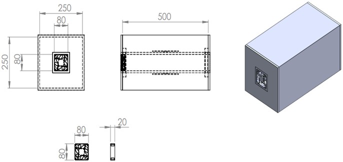
The dimensions of the electronic cabinet are shown in the following figure. The fan on the model provides airflow in the ventilation duct. However, to simplify the simulation conditions and ensure more accurate results, the fan model is not included in the simulation. Instead, flow input is defined at this location.
Fig. 1Schematic representation of the sealed electronic cabinet with overall dimensions. The central ventilation duct and the arrangement of electronic components are shown, serving as the baseline model for CFD simulations
Considering the components that need to be present inside, electronic cabinets under real life conditions, designs are made accordingly. Therefore, it is not very logical for there to be a predominant empty space inside any electronic cabinet. The occupancy in the cabinet interior reduces the amount of air inside the cabinet, thus reducing the amount of heat transfer to the air inside the cabinet, which will cause the cabinet to heat up more. However, since normal conditions in real life are like this, random masses are placed inside the cabinet to provide a true example of the cooling values of the cabinet. These masses are not arranged in any particular order; they are simply placed randomly to ensure more realistic results. However, components that can be applied to an electronic cabinet are positioned within the framework of logic, with reference to the components.
Fig. 2Ventilation duct model without fins, representing the reference configuration. This case is used to evaluate the baseline cooling performance in the absence of extended surfaces
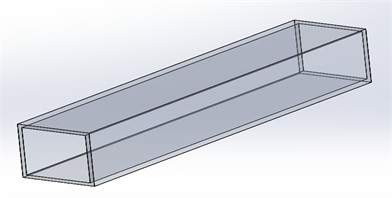
Fig. 3Ventilation duct model with one long fin attached. The figure illustrates how a single fin influences airflow distribution and heat dissipation within the channel
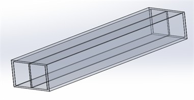
Fig. 4Ventilation duct model with two long fins. This configuration is examined to study the incremental improvement in convective heat transfer with additional fins
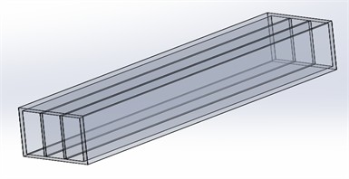
Fig. 5Ventilation duct model with three long fins. The figure highlights the impact of fin density on both airflow resistance and cooling efficiency
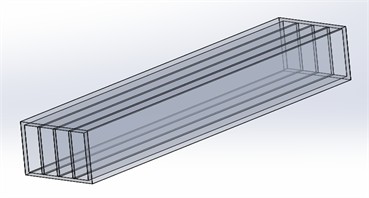
Fig. 6Ventilation duct model with four long fins. The placement of multiple fins demonstrates how extended surfaces enhance heat transfer by increasing the contact area
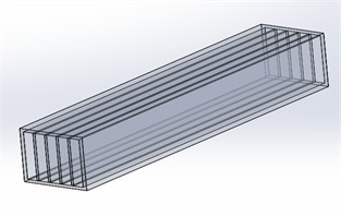
Fig. 7Ventilation duct model with five long fins. This configuration provides the maximum fin density for long fins and allows comparison with fewer fin structures
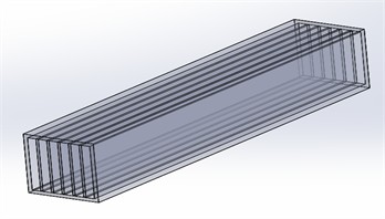
Fig. 8Ventilation duct model with one short fin. The effect of shorter fins on heat transfer performance is assessed in contrast to long fin structures
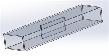
Fig. 9Ventilation duct model with two short fins. The figure shows how limited fin length affects the balance between cooling performance and airflow resistance
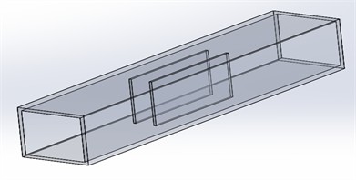
Fig. 10Ventilation duct model with three short fins. This design investigates the relationship between fin number and thermal performance in shorter geometries
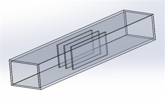
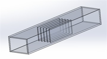
Fig. 11Ventilation duct model with four short fins. The airflow and heat dissipation trends are compared with other short-fin configurations
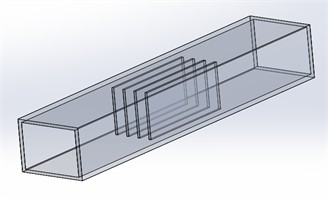
Fig. 12Ventilation duct model with five short fins. This case represents the maximum short-fin density and is used to evaluate cumulative heat transfer effects
The airflow within the ventilation duct is primarily measured for cooling values inside the cabinet with an empty ventilation duct. Subsequently, fins are added to the ventilation duct to increase the amount of heat transfer. Fins of different sizes and numbers show us how the flow inside the duct changes and its effect on heat transfer. In this context, a total of 11 models are studied, including two different fin lengths and five different fin numbers, with reference to an empty ventilation duct. Below are the pictures and information of the ventilation ducts.
In the scope of the study, the outdoor temperature value for simulation results will be set to 40 °C to ensure greater acceptability. Maximum processor temperature must be 90 °C degree and must not exceed this limit value. The outdoor pressure value will be assumed to be 1 atmosphere. AL6061 has been selected for the materials of the enclosure and lid, while FR4 has been chosen for the PCB substrate. A thermal pad will be positioned on the surface where the PCB component generating heat comes into contact with the airflow channel. Silicon carbide has been selected as the material for the thermal pad.
Table 1Material and their thermal properties
Part name | Material | Thermal conductivity [W/m.K] |
Main body | AL6061 | 167.57 |
PCB board | FR4 | 0.38 |
Processor | Copper | 367.49 |
Thermal pad | Silicon carbide | 117.4 |
3. Results
Simulation is performed by educational version of Ansys Fluent software [25]. In the scope of the study, the outdoor temperature value for simulation results is set to 40 °C to ensure greater acceptability. Maximum processor temperature must be 90 °C degree and must not exceed this limit value. The outdoor pressure value will be assumed to be 1 atmosphere. AL6061 has been selected for the materials of the enclosure and lid, while FR4 has been chosen for the PCB substrate. A thermal pad will be positioned on the surface where the PCB component generating heat comes into contact with the airflow channel. Silicon carbide has been selected as the material for the thermal pad.
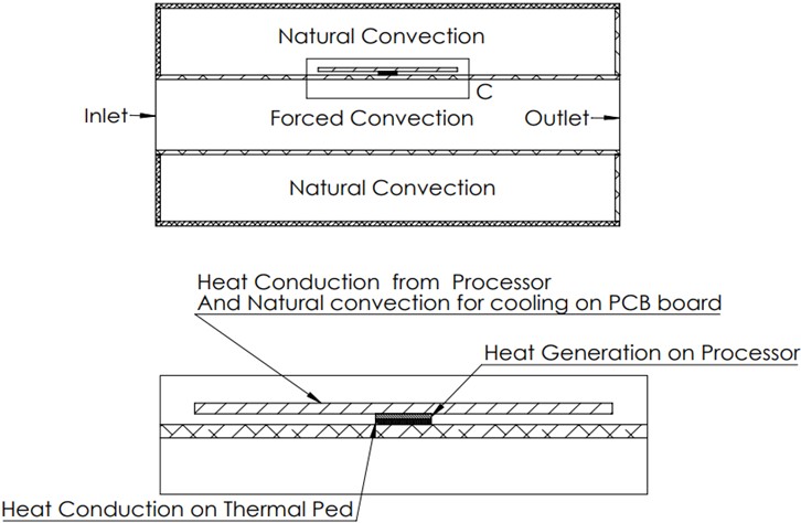
A schematic representation of the heat transfer process within the cabinet is shown in Fig. 13.
3.1. Numerical methodology
To determine whether the airflow regime in the ventilation duct is laminar or turbulent, the Reynolds number (Re) was calculated. The fan selected for the design has dimensions of 80×80×20 mm and an average volumetric flow rate of 60 m3/h, which is representative of commercial fans [26-28]. The volumetric flow rate was converted to SI units:
Fig. 13Schematic diagram of heat transfer mechanisms in the sealed cabinet. The illustration highlights conduction from the processor to the duct surface and convection from the duct walls to the external airflow
Flow velocity calculation. The velocity inside the channel is determined using the volumetric flow rate relation:
Hydraulic diameter. For a square duct, the hydraulic diameter is:
From the table A4 of incropera [29]:
Kinematic Viscosity:
Reynolds number. The Reynolds number is used to identify the flow regime [26]:
Using the air properties at 40 °C (kinematic viscosity 17.2×10⁻⁶ m2/s, from Incropera [29]), the Reynolds number was calculated as:
This Reynolds number is over 10000 and it means our flow is fully turbulent. To calculate the heat transfer coefficient for a square duct with a Reynolds number of 12093, we’ll use the Dittus-Boelter equation for forced convection:
We’ll also use the relationship between the Nusselt number () and the heat transfer coefficient ():
Prandtl number () for air = 0,7 [26].
First, calculate the Nusselt number () using the Dittus-Boelter equation:
Now, use the relationship to find the heat transfer coefficient ():
Solving for :
3.2. Natural convection analysis
In addition to forced convection, natural convection effects were also evaluated in order to better understand the cooling performance of the enclosure. For this purpose, the Grashof number (Gr) was first calculated to determine the buoyancy-driven flow behavior under the given thermal conditions:
So, for a square duct with a side length of 80 mm and a Reynolds number of 12093, the estimated heat transfer coefficient is approximately 25,96 W/m2·K. If we assume a surface temperature of 40 ℃ (or 313,15 K), we can recalculate the Grashof number () and subsequently determine the heat transfer coefficient () for natural convection.
Given:
Surface temperature (T8) = 40 ℃ = 313,15 K.
Thermal conductivity of air () = 0,0257 [26].
Characteristic length () = 500 mm = 0,5 meters.
We’ll use the same process as before to calculate , . First, lets recalculate :
Given that air is at standard conditions, we can use ():
Now, we’ll use the Churchill and Chu correlation to find :
Finally, the heat transfer coefficient is again obtained from:
This result clearly demonstrates that the contribution of natural convection to the cooling performance of the sealed cabinet is very limited compared to forced convection. While forced convection provided a heat transfer coefficient of approximately 26 W/(m2·K), natural convection was found to be only 0.098 W/(m2·K), highlighting the necessity of active airflow or finned structures for efficient thermal management.
So, the estimated heat transfer coefficient for natural convection with a surface temperature of 40 ℃ is approximately 0,0975 W/(m2·K).
While the simulation is being performed, criterions listed below are satisfied. Because natural convection occurs, gravitational force is activated as 9.81 m/s2 on the vertical direction. Mesh check performed and minimum orthogonal quality kept under 0.76. Temperature unit is set to celcius.
The change in pressure over the domain are minimal and their effect on density negligible hence the incompressible ideal gas density formulation is used instead of fully compressible ideal gas model. Operating density set to 111 kg/m3.
3.3. Processor heat generation
The volumetric heat generation rate of the processor is calculated as:
where is the applied heat load (W), and is the processor volume (m3).
Energy source defined for the processor as 100 W and wıth the calculation of processor volume (20 mm×20 mm×2 mm) its heat generation is evaluated as:
3.4. Mass flow rate
At the inlet, the mass flow rate is obtained by:
where is the density of air (kg/m3).
Inlet flow is defined as inlet mass flow rate onto the inlet surface. It is not simulated as a real fan so that simulation capacity is easier to solve. Mass flow rate is calculated below:
3.5. Methodological description
The numerical simulations were carried out using ANSYS Fluent 2023 R1 [25], employing a steady-state solver. To accurately capture the thermal and flow fields inside the sealed electronic cabinet, the following methodological steps were applied:
Mesh Generation and Quality Control: A hybrid unstructured mesh consisting of tetrahedral and hexahedral elements was created to balance computational cost and accuracy. The total number of elements was approximately (to be specified), with local mesh refinement applied near the ventilation duct and processor region to better resolve thermal gradients. The minimum orthogonal quality was maintained above 0.76, and skewness values were kept below 0.25, ensuring numerical stability.
Boundary Conditions:
– The inlet of the ventilation duct was defined as a mass flow inlet corresponding to the volumetric flow rate of 60 m³/h.
– The outlet was set as a pressure outlet at 1 atm.
– The walls of the cabinet and duct were treated as coupled thermal walls, allowing conduction and convection heat transfer. No-slip velocity conditions were imposed on all solid-fluid interfaces.
– Radiation heat transfer was neglected to simplify the model.
Material Properties and Assumptions: The cabinet structure was modeled using aluminum alloy (AL6061), while the PCB substrate was FR4. Thermal pads were represented as silicon carbide material with high conductivity. All properties were assumed to be isotropic and constant with temperature. The fan was not explicitly modeled; instead, a uniform inlet mass flow condition was prescribed, which allows easier convergence but introduces a simplification.
Solver Settings: The flow regime was determined by calculating the Reynolds number (≈12,093), confirming fully turbulent flow. Accordingly, the - turbulence model with standard wall functions was employed. The pressure–velocity coupling was handled using the SIMPLE algorithm. Second-order discretization schemes were applied for momentum, energy, and turbulence equations.
Convergence and Validation: Residual convergence criteria were set to 10⁻6 for continuity, momentum, and turbulence parameters, and 10⁻9 for energy. To validate the solution, the inlet and outlet mass flow rates were compared, and the deviation was found to be below 0.1 %, confirming mass conservation. In addition, the predicted processor surface temperature was cross-checked with analytical estimates using the Dittus-Boelter correlation, ensuring consistency of the results.
Although this study did not include direct experimental validation, efforts were made to ensure the reliability of the CFD model. A grid independence test was conducted, and the results confirmed that further mesh refinement produced less than 2 % variation in processor surface temperature, indicating numerical stability. In addition, the findings of this study are consistent with previously published experimental and numerical works on sealed enclosures [8-10]. For example, Zhang et al. [9] and Bernardoni et al. [10] demonstrated that CFD-based predictions of temperature rise in sealed electronic systems were within 10 % of experimental measurements. These comparisons support the validity of the present modeling approach for analyzing cooling strategies in sealed electronic enclosures.
3.6. Flow and thermal analysis
In addition to the quantitative results, a qualitative evaluation of the flow field reveals that the velocity distribution inside the ventilation duct is strongly influenced by fin geometry. In the no-fin configuration, the airflow remains relatively uniform across the cross-section, but heat transfer is limited due to weak mixing and the absence of flow disturbances. When fins are introduced, localized recirculation regions appear near the fin bases, causing flow separation and vortex formation. These vortices enhance turbulence intensity downstream, which promotes mixing and leads to more efficient convective heat transfer.
The comparison between short and long fins shows different thermal behaviors. Longer fins provide a larger surface area for conduction and convection, thereby reducing the maximum wall and component temperatures. However, this improvement comes at the expense of higher pressure drop due to the reduced effective cross-sectional area. Short fins, on the other hand, maintain relatively lower aerodynamic resistance and provide a more uniform temperature distribution, though with slightly higher peak values.
Overall, the simulations highlight that the interaction between fin number, fin length, and flow behavior plays a decisive role in the cooling effectiveness. The trade-off between enhanced heat transfer and increased flow resistance indicates that fin geometry must be optimized not only for thermal performance but also for hydraulic efficiency in practical designs.
4. Discussion
4.1. Comparison of results
The thermal simulations were performed under varying flow and fin configurations to evaluate their impact on processor temperature and turbulence dissipation within the ventilation channel. The baseline case with almost no airflow in the duct demonstrated extremely poor thermal performance, with the processor temperature rising to approximately 253 °C, far above the operational limit.
Subsequent simulations investigated the effect of introducing airflow through the duct, both with and without fins. In the configuration without fins, the maximum processor temperature was reduced to 121.7 °C, indicating that convection alone significantly improves thermal regulation compared to the no-flow case.
The incorporation of fins into the duct structure further enhanced cooling performance. With a single full fin, the maximum processor temperature decreased to 96.3 °C, and with increasing fin numbers, the temperature progressively declined. The lowest value was obtained with five fins, where the maximum temperature was approximately 78.7 °C, representing a substantial reduction of nearly 40 % compared to the no-fin case.
Partial fin configurations also contributed to improved cooling compared to the no-fin configuration, although they were consistently less effective than full fins. For example, with five partial fins, the processor temperature was 85.9 °C, still below the thermal threshold but higher than the corresponding full-fin configuration. A summary of the results is presented in Table 2.
4.2. Flow behavior and turbulence effects
The CFD results indicate that the flow behavior inside the ventilation duct is strongly influenced by both the number and the length of fins. As the number of fins increases, the turbulence intensity within the duct rises due to enhanced flow separation and vortex formation around fin edges. This elevated turbulence promotes greater mixing, which in turn improves convective heat transfer from the duct surface to the airflow. However, it also results in a higher pressure drop across the channel, implying that in practical applications, the fan power requirement would be greater.
Comparing short and long fins, the longer fins provide a larger surface area for conduction and convection, leading to more efficient heat dissipation. Yet, they also narrow the effective cross-sectional area of the channel, further increasing the flow resistance. In contrast, short fins contribute less surface area enhancement, but maintain lower pressure losses, thereby achieving a balance between thermal and hydraulic performance.
Overall, the interaction between fin geometry and flow behavior demonstrates a clear trade-off: while increasing fin number and length improves cooling effectiveness by intensifying heat transfer, it simultaneously raises aerodynamic resistance. These findings highlight the importance of optimizing fin geometry not only for maximum heat removal but also for sustainable airflow and system efficiency.
In addition to the general trends observed, a more detailed inspection of the flow field indicates the presence of recirculation zones near the fin bases, especially in cases with a higher number of fins. These regions of separated flow create localized stagnation points, which reduce the effective convective heat transfer in those areas. Nevertheless, the increased turbulence intensity in the downstream region compensates for this reduction by enhancing overall mixing and thermal homogenization inside the channel.
Temperature distribution analysis shows that longer fins significantly decrease the peak temperatures on the duct walls and on the contact surfaces with the electronic components. However, they also lead to larger thermal gradients along the channel, suggesting non-uniform cooling performance. In contrast, short fins yield a more uniform distribution of temperature but with a higher overall average temperature, which indicates that fin length must be carefully optimized according to the target application.
Table 2Comparison of thermal simulation results
Flow channel | Maximum processor temp ℃ | Average turbulence dissipation rate in the flow channel (m2/s3) |
No flow | 253,102 | 0 |
No fin | 121,6843 | 0,7606962 |
One fin | 96,30119 | 1,226044 |
Two fins | 94,36519 | 2,356931 |
Three fins | 85,97782 | 3,461611 |
Four fins | 80,80556 | 5,017974 |
Five fins | 78,72218 | 6,621683 |
One fin partial | 106,7067 | 1,140592 |
Two fins partial | 101,1647 | 1,477637 |
Three fins partial | 94,14034 | 1,834628 |
Four fins partial | 89,06109 | 2,213889 |
Five fins partial | 85,85959 | 2,699077 |
Furthermore, the aerodynamic resistance induced by increasing fin number and length results in measurable pressure losses. Although these losses were not critical in the simplified simulation framework, in practical scenarios they would directly translate into higher fan power consumption. This highlights the necessity of balancing thermal and hydraulic performance. The findings emphasize that fin geometry optimization should not solely focus on maximizing heat transfer, but also account for the operational energy efficiency of the entire system.
The results reveal that increasing the fin number initially enhances cooling by enlarging the heat transfer area. However, beyond an optimum threshold, excessive fins restrict airflow, causing higher pressure drops and reduced turbulence intensity in the duct, which limits further improvement in heat removal. Similarly, longer fins improve conduction but may also create flow maldistribution, explaining the observed diminishing returns.
The turbulence dissipation rate provides a useful indicator of airflow mixing inside the duct. Configurations that exhibited higher dissipation rates also showed more uniform temperature distributions and lower processor surface temperatures, confirming the positive correlation between turbulence intensity and cooling effectiveness.
4.3. Limitations of the study
While the study provides valuable insights, several limitations must be acknowledged. First, the fan was not explicitly modeled; instead, a constant mass flow rate was applied to simplify the computational domain. Although this approach improves convergence and reduces computational cost, it may underestimate turbulence generation compared to a real fan model.
Second, radiation heat transfer was neglected. Although conduction and convection are dominant in this configuration, radiation could become significant at elevated surface temperatures.
Third, uniform material properties were assumed for all components, whereas in real electronic systems, material heterogeneity may influence local heat transfer.
Finally, the internal arrangement of non-heating components was simplified by representing them as random blockages without detailed geometrical features. Although this approach helped capture the volumetric influence on airflow distribution, it may not fully reflect the complexity of real electronic assemblies.
Addressing these limitations in future research will enable more accurate and generalizable predictions, ultimately enhancing the applicability of CFD-based design optimization for sealed electronic enclosures.
Another practical consideration is the fan’s power consumption and long-term reliability under sealed conditions. While this study prescribes a fixed flow rate, real-world implementations must balance thermal performance with energy efficiency and noise. Additionally, scalability to larger enclosures may require modular or distributed airflow solutions.
5. Conclusions
The results of this study demonstrate that sufficient cooling of sealed electronic enclosures can be achieved through the integration of an external ventilation duct. The proposed design provides an effective example of maintaining enclosure sealing while ensuring thermal regulation, as the maximum processor temperature remained below the operational threshold of 90 °C in optimized configurations.
In the absence of airflow, the processor temperature rose to nearly 250 °C, highlighting the necessity of forced convection. With airflow alone (no fins), the maximum temperature decreased to ~122 °C, while the addition of fins further improved thermal management. The most effective case was observed with five long fins, where the maximum processor temperature was reduced to approximately 79 °C. These findings confirm the critical influence of fin geometry, as both fin number and length were found to directly enhance heat dissipation. Long fins offered superior heat transfer performance by increasing surface area, while short fins provided more uniform but less effective cooling.
The CFD analysis also revealed that fin-induced turbulence intensifies mixing within the duct, which improves convective heat transfer but simultaneously increases flow resistance. Thus, a clear trade-off between thermal performance and hydraulic efficiency was identified, emphasizing the need for fin geometry optimization.
Despite these promising results, several limitations of the study must be acknowledged. The fan was not explicitly modeled; instead, a mass flow rate was imposed to simplify the analysis. Radiation heat transfer was neglected, and uniform material properties were assumed. These simplifications allowed for efficient simulation but limit the direct applicability of the results to real-world systems.
Future studies should therefore consider more realistic modeling approaches, such as incorporating detailed fan geometry, accounting for radiative heat transfer, and evaluating the impact of alternative fin materials. In addition, experimental validation, optimization of fin geometry using design-of-experiments approaches, and evaluation under varying ambient conditions are needed to establish more robust and generalizable design guidelines. Together, these efforts would provide deeper insight into the interaction between thermal and aerodynamic performance, ultimately guiding the design of more efficient sealed electronic enclosures.
References
-
B. Sarper, “Investigation of optimum geometry and operating parameters in air cooling of electronics,” (in Turkish), Ph.D. Thesis, Karadeniz Technical University, Trabzon, Türkiye, 2018.
-
N. Sözbir, “Single phase forced convection in channels and eletronic cooling,” (in Turkish), Ph.D. Thesis, Istanbul University, Istanbul, Türkiye, 1995.
-
B. B. Samet and M. Bilgili, “An investigation of the direct airflow cooling of electronic boards used in plug-in modules,” (in Turkish), 4th SETSCI Conference Proceedings, Vol. 4, No. 1, pp. 316–322, 2019.
-
Z. J. Zuo, E. H. Dubble, and S. D. Garner, “Compact, double side impingement, air-to-air heat exchanger,” in Proceedings of Symposium on Energy Engineering in the 21st Century (SEE2000) Volume I-IV, pp. 1007–1014, Jan. 2023, https://doi.org/10.1615/see2000.1250
-
S. Lee, “Optimum design and selection of heat sinks,” IEEE Transactions on Components, Packaging, and Manufacturing Technology: Part A, Vol. 18, No. 4, pp. 812–817, Jan. 1995, https://doi.org/10.1109/95.477468
-
Y.-G. Lv, G.-P. Zhang, Q.-W. Wang, and W.-X. Chu, “Thermal management technologies used for high heat flux automobiles and aircraft: a review,” Energies, Vol. 15, No. 21, p. 8316, Nov. 2022, https://doi.org/10.3390/en15218316
-
Z. Zhang, X. Wang, and Y. Yan, “A review of the state-of-the-art in electronic cooling,” e-Prime – Advances in Electrical Engineering, Electronics and Energy, Vol. 1, p. 100009, Jan. 2021, https://doi.org/10.1016/j.prime.2021.100009
-
T. Lee, B. Chambers, and M. Mahalingam, “Application of CFD technology to electronic thermal management,” Proceedings 44th Electronic Components and Technology Conference, Vol. 18, No. 3, pp. 411–420, Jul. 2025, https://doi.org/10.1109/ectc.1994.367557
-
M. T. Zhang, M. M. Jovanovic, and F. C. Lee, “Design and analysis of thermal management for high-power-density converters in sealed enclosures,” APEC 97 – Applied Power Electronics Conference, Vol. 1, No. 3, pp. 405–412, May 2025, https://doi.org/10.1109/apec.1997.581482
-
M. Bernardoni, P. Cova, N. Delmonte, and R. Menozzi, “Heat management for power converters in sealed enclosures: A numerical study,” Microelectronics Reliability, Vol. 49, No. 9-11, pp. 1293–1298, Sep. 2009, https://doi.org/10.1016/j.microrel.2009.06.028
-
V. P. Shatskiy, V. A. Gulevsky, and E. N. Osipov, “Water-evaporative cooling of sealed volumes,” in IOP Conference Series: Earth and Environmental Science, Vol. 659, No. 1, p. 012118, Feb. 2021, https://doi.org/10.1088/1755-1315/659/1/012118
-
A. C. Kheirabadi and D. Groulx, “Cooling of server electronics: a design review of existing technology,” Applied Thermal Engineering, Vol. 105, pp. 622–638, Jul. 2016, https://doi.org/10.1016/j.applthermaleng.2016.03.056
-
M. Kılıç, “Numerical investigation of nanofluid applications in military system,” (in Turkish), The Journal of Defence Science, Vol. 17, No. 1, pp. 1–12, 2018.
-
M. Kiliç and O. Özcan, “A numerical investigation of combined effect of nanofluids and impinging jets for different parameters,” (in Turkish), Gazi Üniversitesi Mühendislik-Mimarlık Fakültesi Dergisi, Vol. 2018, No. 18-2, pp. 1501–1515, Sep. 2018, https://doi.org/10.17341/gazimmfd.460548
-
M. Kiliç, “Investigation of combined effect of nanofluids and impinging jets on cooling of electronic systems,” (in Turkish), Çukurova Üniversitesi Mühendislik-Mimarlık Fakültesi Dergisi, Vol. 33, No. 3, pp. 121–132, Sep. 2018, https://doi.org/10.21605/cukurovaummfd.500597
-
M. Kılıç and M. Efeoğlu, “numerical investigation of effect of nanofluids’ properties on heat transfer,” (in Turkish), in 3rd International Mediterranean Science and Engineering Congress, pp. 1–8, Oct. 2018.
-
T. Tezel, “Experimental investigation of effect of using aluminum foam materials on heat transfer in the cooling of electronic systems,” (in Turkish), M.S. thesis, Akdeniz University, Antalya, Türkiye, 2013.
-
S. Madhavan Nampoothiri, M. Sabu Sebastian, and P. C. Sajith Kumar, “Implementation of peltier cooling in hermetically sealed electronic packaging unit for sub-sea vessel,” Defence Science Journal, Vol. 68, No. 3, p. 326, Apr. 2018, https://doi.org/10.14429/dsj.68.12149
-
F. Coşkun, “Vapor compression refrigeration cycle design for electronic cooling applications,” M.S. thesis, Gebze Technical University, Kocaeli, Türkiye, 2019.
-
G. Gürüf, I. Solmuş, C. Yıldırım, and K. Bilen, “Determination of average volmetric heat transfer coefficient between modified graphite foam and the air,” (in Turkish), in Proceedings of 14th National HVAC-R Conference, Apr. 2019.
-
B. Markal and K. Aksoy, “Innovative cooling technologies: heat pipes,” (in Turkish), in 1st International Symposium on Innovative Approaches in Scientific Studies, pp. 336–342, 2018.
-
W. J. Bilski, G. Baldassarre, M. Connors, J. Toth, and K. L. Wert, “Electronics cooling using a self-contained, sub-cooled pumped liquid system,” in 24th Annual IEEE Semiconductor Thermal Measurement and Management Symposium, pp. 137–141, Mar. 2008, https://doi.org/10.1109/stherm.2008.4509380
-
S. E. Atabay, “Development of diffusion bonded materials for electronics cooling applications,” M.S. thesis, Middle East Tech. University, Ankara, Türkiye, 2017.
-
T. Demircan and E. Özdemir, “Effective cooling of circuit elements at high temperature in military equipment,” (in Turkish), Savunma Bilimleri Dergisi, Vol. 18, No. 1, pp. 27–54, May 2019, https://doi.org/10.17134/khosbd.561191
-
“ANSYS Fluent, Release 2023 R1,” ANSYS Inc., Canonsburg, PA, USA, 2023.
-
T. L. Bergman, A. S. Lavine, F. P. Incropera, and D. P. Dewitt, Incropera’s Principles of Heat and Mass Transfer. Hoboken, NJ, USA: Wiley, 2017.
-
A. Husnu Bademlioglu, O. Bedrettin Karatas, K. Furkan Sokmen, and E. Yuruklu, “Thermal management and fin characteristic optimization of an electronic power supply utilizing Taguchi and ANOVA methods,” Applied Thermal Engineering, Vol. 252, p. 123671, Sep. 2024, https://doi.org/10.1016/j.applthermaleng.2024.123671
-
A. A. Lad, E. Roman, Y. Zhao, W. P. King, and N. Miljkovic, “Fin design topology optimization for direct liquid cooling of multichip power modules,” IEEE Transactions on Components, Packaging and Manufacturing Technology, Vol. 14, No. 5, pp. 795–809, May 2024, https://doi.org/10.1109/tcpmt.2024.3363050
-
J. Li, “A review of structural optimization in single-phase liquid-cooled heat sinks,” International Journal of Heat and Mass Transfer, Vol. 215, p. 124200, 2023.
-
S. S. Raza, “A comprehensive review on computational fluid dynamics analysis and optimization of open micro-channel heat sinks with pin fins,” International Journal for Research in Applied Science and Engineering Technology, Vol. 12, No. 8, pp. 884–893, Aug. 2024, https://doi.org/10.22214/ijraset.2024.64024
-
K. Ersoy, “Review of electronic cooling and thermal management in space and aerospace applications,” Engineering Proceedings, Vol. 89, No. 42, p. 42, Mar. 2025, https://doi.org/10.3390/engproc2025089042
-
A. M. M. Elshazly, M. S. Soliman, M. E. A. Elsheikh, and S. A. Mohamed, “Investigation of heat sink performance using CFD for electronic cooling applications,” Advanced Materials Research, Vol. 939, pp. 214–223, 2014.
-
N. H. Hamad, A. M. Adham, and R. S. Abdullah, “Cooling electronic components by using nanofluids: a review,” Journal of Thermal Analysis and Calorimetry, Vol. 149, No. 22, pp. 12503–12514, Oct. 2024, https://doi.org/10.1007/s10973-024-13711-6
-
G. Zhang, “Recent developments in cooling technologies for high power electronic devices,” Advances in Interdisciplinary Engineering, Lecture Notes in Networks and Systems, Vol. 552, pp. 95–109, 2023.
About this article

The authors have not disclosed any funding.
The datasets generated during and/or analyzed during the current study are available from the corresponding author on reasonable request.
Cevat Mübarek Tarhan: data curation, formal analysis, investigation, methodology, software development, validation, visualization, and writing-original draft preparation throughout the entirety of this study. Dr. Ahmet Feyzioğlu: conceptualization, methodology, writing, reviewing and editing. Prof. Dr. Gunther Brenner: conceptualization, methodology, writing, reviewing and editing.
The authors declare that they have no conflict of interest.
