Abstract
To address the resonance peak issue of LCL (Inductor capacitor inductor) grid-connected inverters at the resonant frequency and reduce system losses caused by passive damping, this paper proposes a novel plug-in composite repetitive controller based on an active damping strategy utilizing a notch filter, along with detailed parameter design for the controller. Simulation results demonstrate that the notch filter-based repetitive controller maintains high gain at the fundamental frequency while exhibiting rapid gain attenuation at higher frequencies. Since the harmonic content of the inverter system is predominantly concentrated in the low-frequency range, the controller achieves excellent harmonic suppression performance within the low-frequency region. The low gain at high frequencies enhances system stability. Compared with conventional repetitive controllers, the proposed controller adopts a low-loss notch filter damping method, preserves the superior harmonic suppression capability (the grid current harmonic is reduced by 1.37 %), and improves system stability.
Highlights
- A model of a single-phase grid-connected inverter was established. Detailed parameter design for the proposed composite current controller was conducted, followed by simulation analysis of its steady-state and dynamic performance, which verified the effectiveness of the proposed scheme.
- common damping methods are introduced briefly, and active damping methods based on a notch filter are studied deeply, including analysis and verification.
- an improved composite repetitive controller based on a notch filter was proposed for suppressing harmonics, reducing steady-state errors of the grid-connected inverter.
1. Introduction
With the energy crisis and environmental pollution, distributed power generation systems (DPGS) based on renewable energy have attracted more and more attention [1]. A grid-connected inverter, as an important interface between the distributed generation and the power grid, will generate a large amount of harmonics while it works. Thus, in order to suppress harmonic and smooth current, an LCL filter is usually adopted in grid-connected inverters. Due to the presence of a resonant peak and 180° phase lag at the resonant frequency of the LCL filter, this phenomenon introduces a pair of unstable closed-loop poles in the right-half s-plane, threatening system stability. To mitigate this resonance, damping methods are essential. The Reference [2] categorizes, compares, and summarizes various damping methods. While passive damping offers one solution, active damping methods are often preferred for their higher efficiency. Active damping is widely adopted due to its superior controllability and adaptability compared to passive damping. For instance, Reference [3] applied this method to a wind grid-connected power system. However, as active damping requires additional components like sensors, which increase system complexity and cost, the notch filter-based damping method has been developed to address these drawbacks. The notch filter stands out as a particularly effective and widely adopted active damping strategy for LCL-type inverters, as evidenced by its application in Reference [4]. Its primary advantages are simplicity and the elimination of additional physical sensors, making it a practical and cost-effective choice.
Repetitive Control (RC), which is based on the internal model principle, is an effective method to eliminate harmonic pollution produced by nonlinear loads or grid background harmonics. For instance, Reference [5] applied RC to an APC system, demonstrating improved system frequency adaptability, while Reference [6] applied it to an inverter control system, enhancing the accuracy of phase lead compensation. Conventional RC (CRC) has a slow dynamic response due to the delay of one fundamental cycle, which cannot track the reference current in time. To achieve a better control effect, it is necessary to improve the conventional repetitive controller. The main research content of the article includes the following points.
Firstly, the plug-in composite repetitive controller, formed by connecting a plug-in repetitive controller and a PI controller in series, enhances the dynamic performance of the RC system and improves the tracking accuracy of error signals.
Secondly, a comparative analysis of LCL resonance peak damping methods was conducted. The notch filter damping method is applied to the inverter control system as an LCL resonance peak suppression technique in the composite repetitive controller. This sensorless active damping approach reduces system hardware complexity and minimizes losses associated with passive damping.
Thirdly, a detailed design and analysis of the parameters for the proposed composite repetitive controller were carried out, and the stability of the system was thoroughly examined. A comparative simulation analysis was conducted on the steady-state and dynamic performance of PI, CRC, and the proposed composite RC.
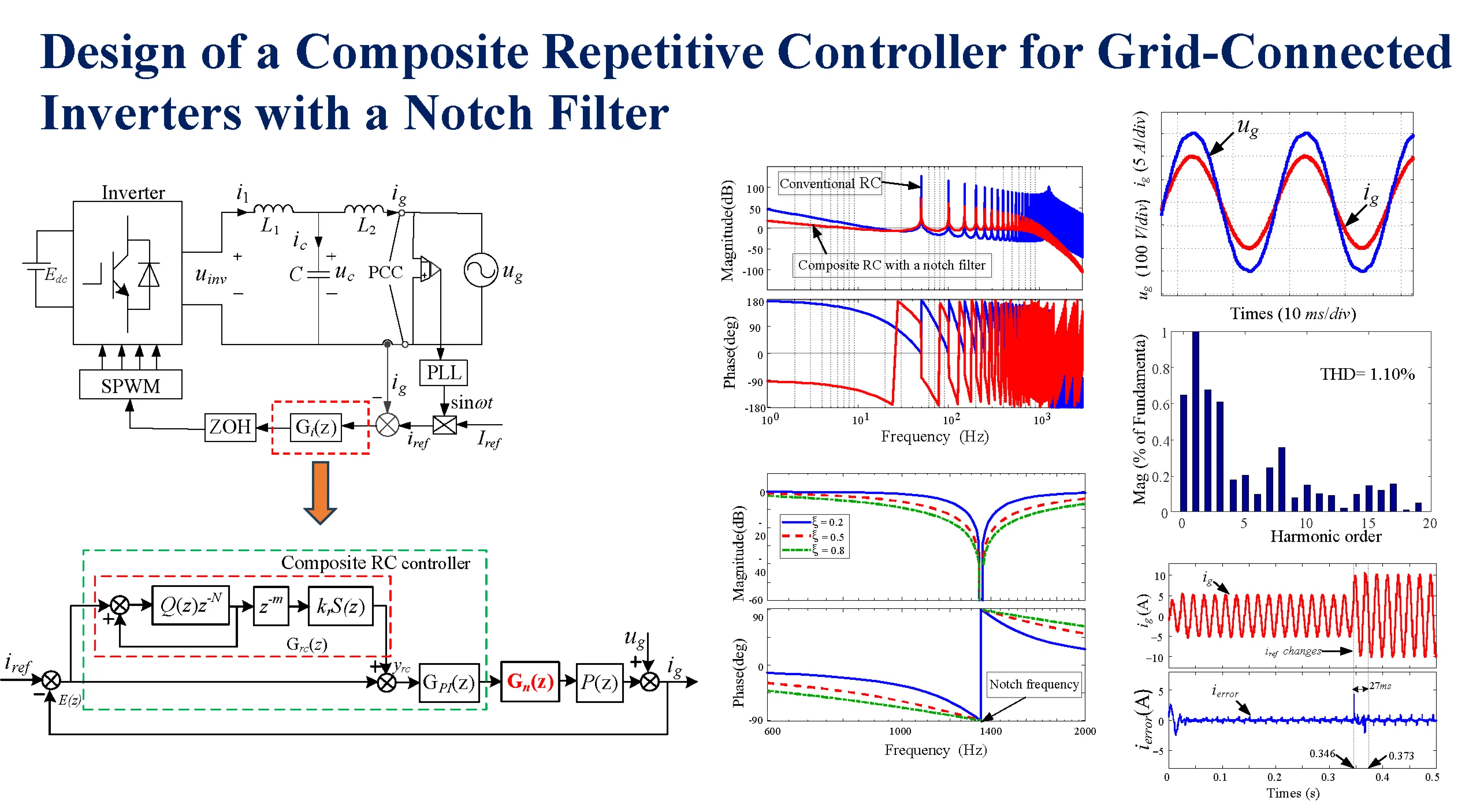
The overall research methodology is summarized in the flowchart depicted in Fig. 1.
2. Description of the single-phase grid-connected inverter
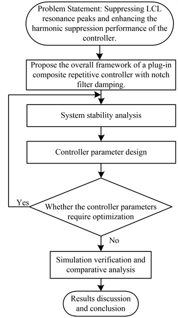
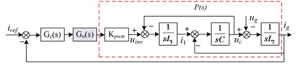
The proposed control system is shown in Fig. 2. is the DC bus voltage, is the inverter output voltage, , , and are the nominal values of the LCL filter, respectively. is the tracked reference current; the symbols and denote the inductor currents in the circuit; is the capacitor current; is the grid voltage; is a current controller. The Zero-order hold (ZOH) serves as the discrete-time signal reconstruction unit, while the Point of common coupling (PCC) represents the electrical interface between the converter and the utility grid. A phase-locked loop (PLL) generates two critical control parameters: (1) the instantaneous phase angle of the grid voltage. (2) The frequency ratio between the sampling frequency (f and grid fundamental frequency ().
Grid-connected inverters usually use high-frequency SPWM modulation technology, with a switching frequency of over 10 kHz, so the inverter can be regarded as a unit, whose gain is 1. The transfer function from input to output as the plant , it can be described as follows:
The resonant frequency of the LCL-type filter is:
Fig. 1Flowchart for designing and validating the composite repetitive controller
3. Resonant damping control strategy
3.1. Passive damping
As shown in Fig. 2, passive damping is directly connected in series or parallel with a resistor on the LCL filter element, changing the impedance of the filter to increase damping and suppress the resonant peak. For example, a capacitor in series with a resistor , and selecting an appropriate damping resistance value, the resonant peak will be effectively suppressed.
Fig. 2Diagram of a single-phase grid-connected inverter
3.2. Active damping
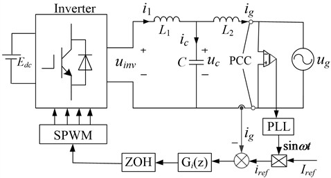
The passive damping method is simple and reliable, but due to the addition of resistance, it increases system losses and reduces the attenuation ability of high-frequency harmonic signals, so the active damping method was developed. The active damping method corrects the resonant frequency characteristics of the LCL filter directly on the control loop by using appropriate control algorithms. There are generally two types of active damping methods: one is based on state variable feedback, and the other is based on a notch filter. Active damping based on state variables feedback usually adopts the LCL filter capacitor current feedback, such as in Reference [7]. Active damping based on notch filters is achieved by connecting notch filters in series in the control loop, which adds a pair of zeros at the resonant frequency to counteract the under-damped resonant poles of the LCL filter, thereby changing the damping characteristics of the system and eliminating resonant peaks [8]. The bode diagrams of the plant have no damping, passive damping, active damping by capacitive current feedback, or a notch filter, respectively. As shown in Fig. 3.
Fig. 3Bode diagram of the plant has no damping, passive damping, and active damping
The advantages and disadvantages of passive damping and active damping are listed in Table 1.
Table 1Advantages and disadvantages of passive damping and active damping
Damping | Advantages | Disadvantages |
Passive damping | Simple and reliable | Generate resistance losses |
Active damping by capacitive current feedback | No resistance losses | Require sensors, increases the complexity and the hardware cost of the system |
Notch filters damping | Simple and does not require sensors | Adds a pair of zeros at the resonant frequency; design difficulty |
The active damping algorithm based on notch filters is simple, and it does not require high-precision sensors. However, there are also difficulties in designing notch filter parameters due to phase delay or uncertainty resonant frequency. These issues are increasingly being addressed by many scholars. For example, robust active damping has been successfully applied in LCL filters in [8], and adaptive notch filters have been used in MMC-HVDC Systems in [9].
4. Composite RC for grid-connected inverters with a notch filter
4.1. Notch filter
The function of a notch filter is to introduce a pair of zeros to cancel the resonant poles of the LCL filters, and a notch filter has a negative peak to eliminate the resonant peak of the LCL filter at the resonant frequency. In other words, the core principle of notch filter damping is to introduce a frequency response at the resonant frequency of the control loop that is exactly opposite to the characteristics of the resonance peak, thereby achieving precise “cancellation” of the resonance peak.
Fig. 4 shows that the connection between the controller circuit and the notch filter is in series. The active damping closed-loop control diagram of a single-phase inverter with an LCL filter based on a notch filter is shown as follows. is the transfer function of the controller, is the plant, and is the transfer function of the notch filter, which is an Infinite impulse response (IIR) digital filter.
Fig. 4Control scheme based on a notch filter
According to Reference [10], the transfer function of a notch filter is shown as:
where is the notch angular frequency, most of the signal will be attenuated at this frequency. The notch filter must exhibit ideal frequency-selective attenuation, achieving complete nullification (0 gain or –∞ dB) at the target frequency while maintaining unity gain (0 dB) across all other frequencies. The damping ratio plays a critical role in this design, as it governs both the filter’s interference rejection capability and resonant peak suppression performance. Setting a reasonable damping ratio can improve the anti-interference ability and resonant peak suppression effect.
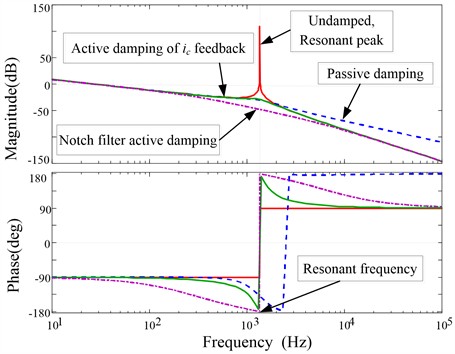
Fig. 5The Bode diagram of a notch filter with different ξ (0 <ξ< 1)

The frequency response curves under different damping ratios are shown in Fig. 5. It can be clearly observed that a decrease in the damping ratio leads to a sharper notch characteristic. For example, when the damping ratio is reduced from 0.8 to 0.2, the depth of the notch increases while its width narrows. Conversely, the notch filter depth decreases while the width increases with an increasing value of . If the notch filter depth becomes shallow, the suppression effect of resonance peaks is reduced, and the phase margin at low frequencies is also reduced; otherwise, if the notch width is narrow the system is sensitive to the variations of the resonant frequency, resulting in the frequency of the notch filter cannot be accurately equal to the resonant frequency, and that will be reduce the robustness of the notch filter. As shown in Fig. 5, when the damping ratio is close to 1, such as 0.8, the notch filter has more robustness.
4.2. Active damping control based on composite RC with a notch filter
4.2.1. Composite repetitive controller with active damping
The PI (Proportional integral) controller is used to improve the stability of the controlled object and the dynamic response speed, while RC is used to improve the accuracy for tracking the reference current and suppressing harmonics. To make the system have faster dynamic response speed and higher wave output quality, a compound repetitive controller composed of PI and RC is proposed. There are two structural types of composite RC, including PI and RC are in series or in parallel connection, and the serial structure also includes plug-in and cascade. A composite RC with RC and PI plug-in connection is proposed based on a notch, as shown in Fig. 6.
Fig. 6Diagram of active damping control based on a notch filter
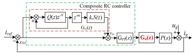
is the RC controller, is the PI controller, is the notch filter, and is the plant. The discrete expression of the RC controller is:
where is the internal mode filter of RC, and is usually designed as a constant less than 1 or a zero phase low-pass filter, is the number of delayed beats per cycle of RC, is the phase-lead compensator, is the RC gain, and is the compensator of RC. The PI controller transfer function is:
where is the proportional coefficient and is the integral coefficient. From RC controller output to the system output can be seen as a new controlled object of the RC, including the PI controller and the notch filter, and it can be described as:
Assuming is the plant without a notch filter, draw the zero and pole distribution maps of and , respectively.
Fig. 7Zero and pole distribution maps of P0z and P0*z
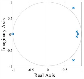
a) without a north filter
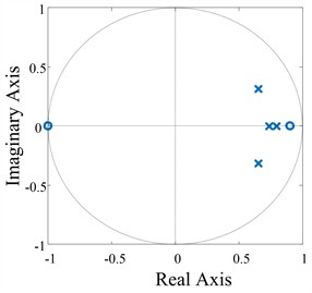
b) with a north filter
As shown in Fig. 7(a), It is clear that the controlled object has two poles outside the unit circle, which will lead to system instability, while all the poles of inside a unit circle in Fig. 7 (b), so the equivalent controlled object is stable by active damping of the notch filter.
4.2.2. System stability analysis
As shown in Fig. 6, the error transfer function of in the discrete domain is:
The characteristic polynomial of the system is:
According to the Small-gain Theorem, the prerequisite for system stability is that the following two conditions need to be met: Firstly, the roots of the characteristic equation are all within a unit circle, which can be met by selecting appropriate values of and ; Secondly, the following equation is valid:
Substituting Eq. (4) into Eq. (10) and performing computational analysis yields the following expression:
When the frequency of the reference signal and disturbance signal is a fundamental frequency or its integral multiples, then:
Consequently, Eq. (11) admits the following simplified form as:
According to the expression :
where and are the amplitude frequency characteristics, and are the phase frequency characteristics of and , respectively. Substituting Eq. (14) in Eq. (13), it can be results in the following expression:
According to the Euler formula, the exponential function in Eq. (15) is expanded:
4.2.3. Design of the composite RC
1) Compensator . According to Reference [11], the compensator can choose a fourth-order Butterworth low-pass filter, with the cut-off frequency set to 850 Hz. The discrete expression is:
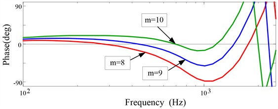
2) Design the phase-lead compensator . The Bode diagram of is illustrated in Fig. 8 with three typical values of . It is clear that within the frequency 1 kHz range, the compensated phase frequency curve is closest to the 0 dB line when 10, which can be chosen as the lead beat.
Fig. 8Bode diagram of P0zSzzm
3) Design of RC gain . The RC gain has a significant impact on the system stability. According to Eq. (17), the maximum can be selected as:
For 10, the magnitude-phase characteristics of in Fig. 9 show that within a 1 kHz frequency range, the phase varies from 1.89° to –15°, and the magnitude varies from 0.0123 dB to –11.5 dB. Therefore, the maximum value of is:
Considering modeling errors, the maximum is selected as 1.5 (0 1.5). According to Eq. (13), define as the error convergence of the characteristic equation, and substitute . can be described as:
Fig. 9Frequency response of P0zSzzm within 1 kHz
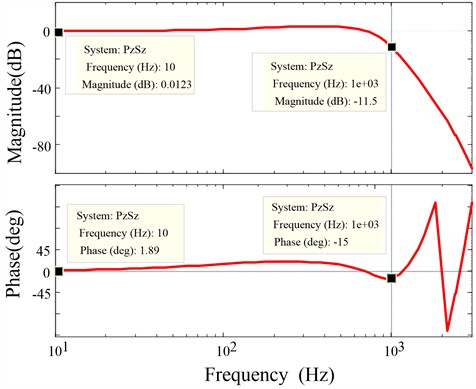
Fig. 10Nyquist diagram of P0zSzkrz10
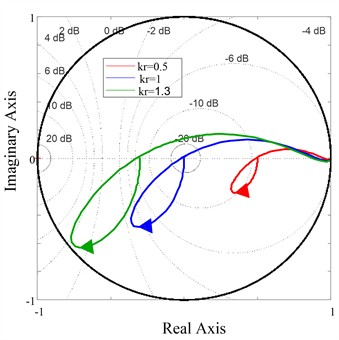
To analyse the system stability conditions for different clearly, Fig. 10 shows Nyquist curves of with three typical values of , . When value is 0.5, 1, and 1.3, respectively, the Nyquist curves of are plotted. The closer the Nyquist locus is to the unit circle’s center, the higher the stability of the system. It is clear that when 1.3, the trajectory of is within a unit circle. However, when exceeds 1.3, the Nyquist locus moves outside the unit circle, indicating system instability. When 1, the trajectory is closer to the center of the circle, and the system has more stability margin.
4) Parameter optimization design of the controller. The internal model is an important component for keeping the system stability, as it can keep the poles of the ideal RC controller within a unit circle. The choice of varies in different application situation, when the performance requirements of the control system are not high, can be selected as a constant less than 1 (such as 0.95, 0.98, etc.); another situation where there is a high demand for control system performance, a zero phase low-pass filter is usually employed by . According to Reference [11], the expression of a zero-phase low-pass filter is:
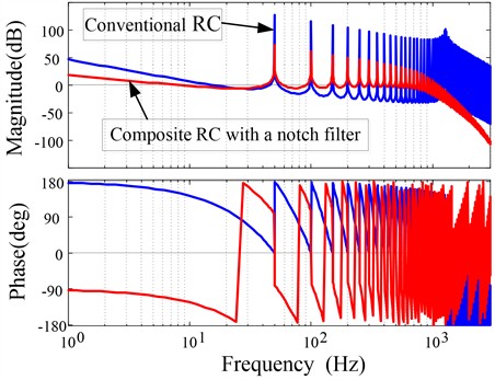
is the internal mode order of RC; it equals the ratio of sampling frequency to fundamental frequency; the larger , the higher accuracy for RC. The reference signal of a single-phase grid-connected inverter system is a sine signal, if the fundamental frequency is 50 Hz, while the sampling frequency is 10 kHz, which correspondences with the system switching frequency, can be calculated as 200. Based on the above design parameters for RC, the open-loop Bode diagram of the composite RC is shown in Fig. 11.
Although conventional RC provides high gain at low frequencies, it still has high gain at high frequencies, leading to system instability. The gain of the composite RC controller with a notch filter can reach 72.4 dB at the fundamental frequency and at the fundamental frequency, and within the range of 1 kHz, the composite RC can maintain high gain at integer multiples of the fundamental frequency. When the frequency reaches to 1 kHz, the gain quickly decays to 8.26 dB, and then gradually decays rapidly as the frequency increases.
Fig. 11Bode diagram of composite RC with a notch filter
5. Simulation analysis of harmonic suppression performance
To validate the effectiveness of the proposed scheme, we developed a 2.2 kW inverter simulation model with parameters as specified in Table 2.
As shown in Fig. 12, 13, and 14, when the grid simulator injected harmonic current signals exceeding 5 %, the THD (Total harmonic distortion) of the grid current was reduced to 4.74 % with PI control; while the CRC system was adopted, harmonics decreased to 2.47 %. In contrast, the proposed composite RC scheme achieved a significantly lower harmonic distortion of only 1.1 %. As shown in Fig. 15, to validate the dynamic performance of the system, when the grid reference current abruptly changes from 5 A to 10 A, a comparison between CRC and the proposed composite RC demonstrates that the proposed composite RC achieves a smaller steady-state error and faster response speed. These results demonstrate the remarkable harmonic suppression capability of the proposed method, confirming its effectiveness in power quality improvement.
Table 2Parameters for the inverter system
Parameters | Symbols | Value |
DC voltage | 380 V | |
RMS of grid voltage | 220 V | |
Inverter side inductor | 3.8 mH | |
Grid-side inductor | 2.3 mH | |
Filter capacitor | 10 μF | |
Grid frequency | 50 Hz | |
Sampling frequency | 10 kHz |
Fig. 12PI steady-state performance
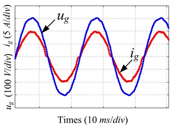
a) Waves of and
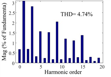
b) THD of
Fig. 13CRC steady-state performance
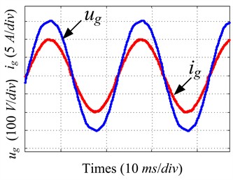
a) Waves of and
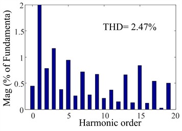
b) THD of
Fig. 14The proposed composite RC steady-state performance
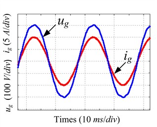
a) Waves of and
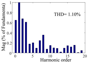
b) THD of
Fig. 15Transient response
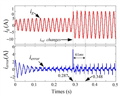
a) CRC
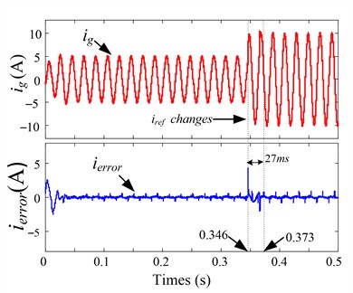
b) The proposed composite RC
6. Conclusions
The main tasks completed in this paper include some items as follows.
Firstly, common damping methods are introduced briefly, and active damping methods based on a notch filter are studied deeply, including analysis and verification.
Secondly, an improved composite repetitive controller based on a notch filter was proposed for suppressing harmonics, reducing steady-state errors of the grid-connected inverter.
Thirdly, the parameters of the proposed controller were meticulously designed and validated.
The system stability was analyzed, and its steady-state and transient responses were simulated. A comparative analysis of the output voltage, current waveforms, and THD of current for the PI, CRC, and the proposed composite RC schemes, the simulation results demonstrate that the proposed composite RC offers superior harmonic suppression and dynamic response performance. Moreover, the introduction of notch filter damping reduces the system gain at high frequencies, and high-frequency attenuation can improve system stability. Meanwhile, the proposed controller provides high gain at low frequencies, which not only enables the controller to track the reference signal without error, but also suppresses low-frequency harmonics.
However, there is still much more work needed to conduct in-depth further research about composite RC for grid-connected inverters in the future. Furthermore, the present study has not yet considered the impact of weak grid conditions, such as grid frequency fluctuations and disturbances. The influence of inverter control system delays on the control effectiveness remains to be investigated. Additionally, a wide-range active damping notch filter, an adaptive LCL filter at the resonant frequency, etc. These aspects will be addressed in future work.
References
-
A. Rolan, S. Bogarra, and M. Bakkar, “Integration of distributed energy resources to unbalanced grids under voltage sags with grid code compliance,” IEEE Transactions on Smart Grid, Vol. 13, No. 1, pp. 355–366, Jan. 2022, https://doi.org/10.1109/tsg.2021.3107984
-
W. Wu, Y. Liu, Y. He, H. S.-H. Chung, M. Liserre, and F. Blaabjerg, “Damping methods for resonances caused by lcl-filter-based current-controlled grid-tied power inverters: an overview,” IEEE Transactions on Industrial Electronics, Vol. 64, No. 9, pp. 7402–7413, Sep. 2017, https://doi.org/10.1109/tie.2017.2714143
-
T. Wang, M. Jin, Y. Li, J. Wang, Z. Wang, and S. Huang, “Adaptive damping control scheme for wind grid-connected power systems with virtual inertia control,” IEEE Transactions on Power Systems, Vol. 37, No. 5, pp. 3902–3912, Sep. 2022, https://doi.org/10.1109/tpwrs.2021.3140086
-
S. Somkun, S. Srita, T. Kaewchum, A. Pannawan, C. Saeseiw, and P. Pachanapan, “Adaptive notch filters for bus voltage control and capacitance degradation prognostic of single-phase grid-connected inverter,” IEEE Transactions on Industrial Electronics, Vol. 70, No. 12, pp. 12190–12200, Dec. 2023, https://doi.org/10.1109/tie.2023.3237904
-
H. Lin, X. Guo, D. Chen, S. Wu, and G. Chen, “A frequency adaptive repetitive control for active power filter with 380V/75A SiC-inverter,” IEEE Transactions on Industry Applications, Vol. 58, No. 4, pp. 5469–5479, Jul. 2022, https://doi.org/10.1109/tia.2022.3176848
-
Q. Zhao and Y. Ye, “Fractional phase lead compensation RC for an inverter: analysis, design, and verification,” IEEE Transactions on Industrial Electronics, Vol. 64, No. 4, pp. 3127–3136, Apr. 2017, https://doi.org/10.1109/tie.2016.2631516
-
H. Zhang, X. Wang, Y. He, D. Pan, and X. Ruan, “A compensation method to eliminate the impact of time delay on capacitor-current active damping,” IEEE Transactions on Industrial Electronics, Vol. 69, No. 7, pp. 7512–7516, Jul. 2022, https://doi.org/10.1109/tie.2021.3100993
-
W. Yao, Y. Yang, X. Zhang, F. Blaabjerg, and P. C. Loh, “Design and analysis of robust active damping for LCL filters using digital notch filters,” IEEE Transactions on Power Electronics, Vol. 32, No. 3, pp. 2360–2375, Mar. 2017, https://doi.org/10.1109/tpel.2016.2565598
-
J. Man, L. Chen, V. Terzija, and X. Xie, “Mitigating high-frequency resonance in MMC-HVDC systems using adaptive notch filters,” IEEE Transactions on Power Systems, Vol. 37, No. 3, pp. 2086–2096, May 2022, https://doi.org/10.1109/tpwrs.2021.3116277
-
Q. Zhao, F. Liang, and W. Li, “A new control scheme for LCL-type grid-connected inverter with a Notch filter,” in 2015 27th Chinese Control and Decision Conference (CCDC), pp. 4073–4077, May 2015, https://doi.org/10.1109/ccdc.2015.7162637
-
F. Liang, H.-J. Lee, and Q. Zhao, “A novel fractional delay proportional-integral multi-resonant-type repetitive control based on a farrow-structure filter for grid-tied inverters,” Electronics, Vol. 12, No. 19, p. 4010, Sep. 2023, https://doi.org/10.3390/electronics12194010
About this article

This work was supported by the Science and Technology Research of Henan Province under Grant 242102240115.
The datasets generated during and/or analyzed during the current study are available from the corresponding author on reasonable request.
Fen Liang: Conceptualization, methodology, validation, formal analysis, writing-original draft preparation, writing-review and editing, funding acquisition. Xiao Liang: Conceptualization, methodology. Huanke Cheng: formal analysis, writing-review and editing. Ho Joon Lee: validation, writing-review and editing
The authors declare that they have no conflict of interest.
