Abstract
The transport of material by vibratory conveyors involves micro-throws of particles, which can be undesirable for certain materials. This study investigates body motion in a conveyor trough whose bottom executes harmonic oscillations perpendicular to the transport direction, while the side walls undergo asymmetric oscillations. The methodology combines mathematical modelling and laboratory experiments. Numerical integration of the governing differential equations using a fourth-order Runge-Kutta scheme yielded the body displacement over one oscillation period, which enabled estimation of the average conveying speed and, consequently, the throughput. The study substantiates the concept and demonstrates the feasibility of the proposed vibratory-conveyor architecture. The results can inform the design of conveyors with throughput regulated by adjusting oscillation frequency or amplitude.
Highlights
- The article investigates the motion of a body in a vibrating conveyor trough, in which the bottom performs harmonic oscillations perpendicular to the direction of transportation, while the side walls perform asymmetric oscillations.
- A mathematical model of body motion was developed for various cases of platform motion.
- As a result of numerical integration of the equations of motion, the dependences of the average transportation speed on the parameters of the platform motion, the walls of the trough, and the coefficients of body friction between the platform and the walls of the trough were obtained.
- The proposed device can be used in practice to perform various technological tasks, since the transportation speed depends on the platform frequency of oscillation and the walls of the trough, which can be easily changed using a frequency converter.
1. Introduction
Vibratory machines are widely used in industry and agriculture to transport discrete and bulk materials and they often operate as subsystems within larger process lines. The throughput of such equipment depends on oscillation amplitude and frequency, parameters that can be tuned over a wide range to meet process requirements. Inertial and vibratory conveyors are classes of oscillatory conveyors characterised by low power demand and reliable operation. In inertial conveyors, transport is produced by biharmonic trough motion at low frequency and large amplitude (up to 0.15 m), whereas vibratory conveyors operate at high frequency (up to 100 Hz) and small amplitude (≈ 0.15-0.2 mm). Because transport relies on micro-throws of particles, these devices are unsuitable for certain materials (e.g., metal shavings, wet sugar, concrete). Significant contributions to vibratory transport have been reported by researchers at Lviv Polytechnic. The benefits of electromagnetic drives are discussed in [1]; dynamic parameters for the bolts transport of various sizes are examined in [2]; and broader applications of vibratory machines are analysed in [3]-[5]. The effect of transverse trough oscillations normal to the sliding plane has been investigated in [6]-[9]. To reduce friction between the load and the trough in inertial conveyors, imparting horizontal transverse oscillations has been proposed, which increases throughput [10]-[12]. High-frequency excitation of a platform can also reduce friction between the body and the surface [13]-[15]. Waveform asymmetry has been proposed to increase mean conveying speed [16, 17]. Friction reduction due to torsional excitation in shaft-bushing systems is reported in [18]. Body motion along an inertial-conveyor trough is analysed in [19] and a combined numerical-experimental study of a vibratory conveyor for bulky and loose products is presented in [20]. A drawback of systems with transverse trough oscillations is that the conveyed load moves not only along the trough axis but also follows wall oscillations in the transverse direction. The associated inertial forces must be overcome, which increases energy consumption and the required drive power.
2. Methodology
2.1. Theoretical research
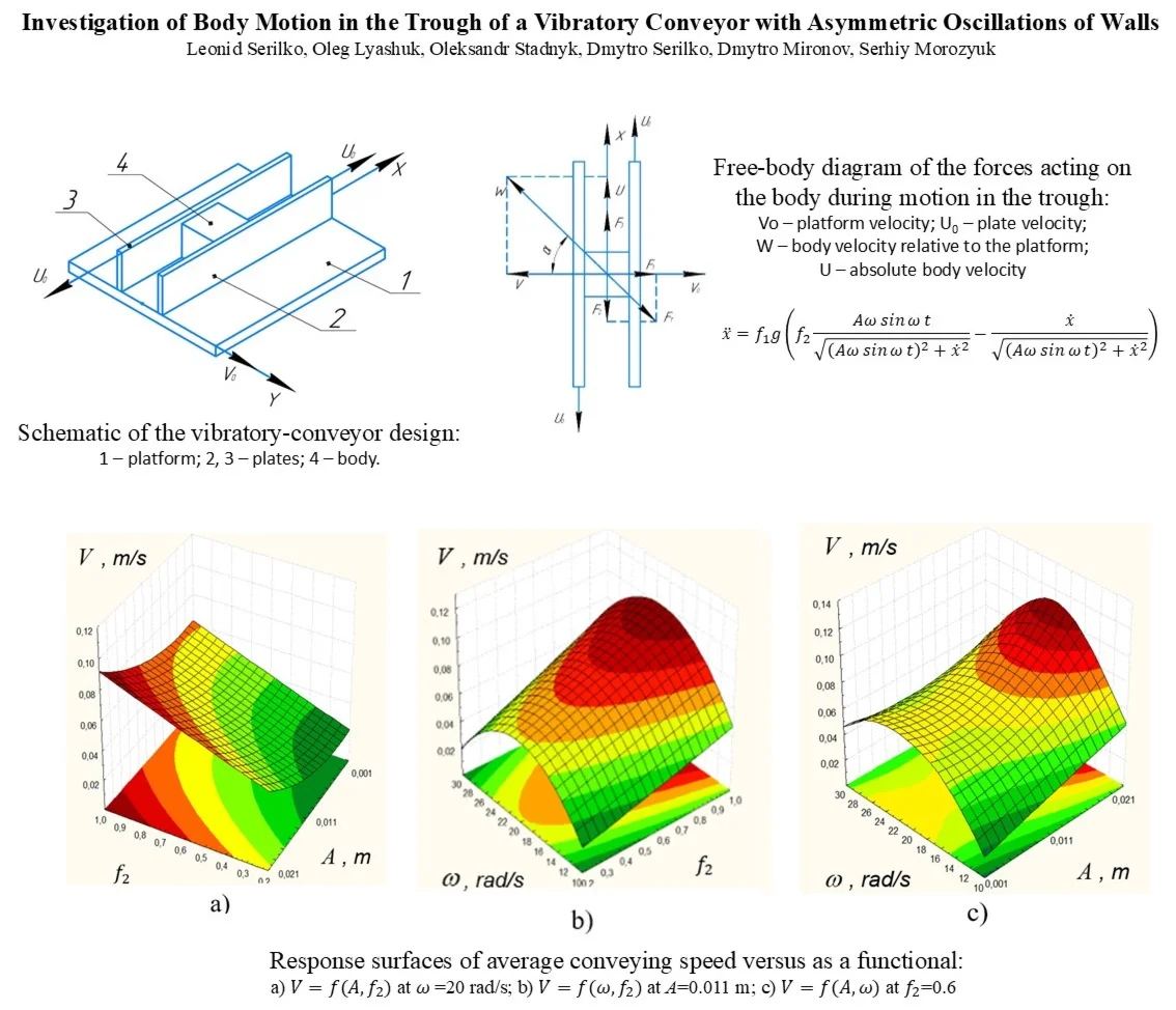
We consider a vibratory-conveyor configuration schematized in Fig. 1. It comprises a horizontal platform (1) that performs harmonic oscillations along the -axis and two plates (2, 3) between which the body 4 is located. To determine the mean conveying speed, which is the main performance indicator for conveyors, we first analyse body motion on platform 1 moving at velocity . Plate 2 moves at , whereas plate 3 is fixed.
As the platform moves, friction at the platform-body interface presses the body against plate 2; simultaneously, friction at the body-plate interface drives motion along the -axis. In the proposed device, the trough bottom undergoes only transverse oscillations, whereas the walls execute asymmetric longitudinal oscillations. Accordingly, the bottom alternately presses the body against the wall that, at a given instant, moves in the conveying direction. Friction with that wall produces purely longitudinal motion without transverse oscillation, so input energy is spent on translation alone, reducing the process energy demand.
The velocity of the body on the platform surface is given by Fig. 2:
where is the absolute velocity of the body along the -axis; is the body’s velocity relative to the platform (opposite the platform motion).
Fig. 1Schematic of the vibratory-conveyor design: 1 – platform; 2, 3 – plates; 4 – body
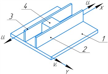
Fig. 2Free-body diagram of the forces acting on the body during motion in the trough: V0 – platform velocity; U0 – plate velocity; W – body velocity relative to the platform; U – absolute body velocity
Resolving frictional force into components gives:
where , , is the coefficient of friction between the platform and the body.
The plate-body friction is:
The equation of motion reads:
i.e.:
With the substitution:
and constant , we obtain:
Combining with Eq. (5) yields:
hence:
Integrating Eq. (9) gives and the body velocity. If , then and so:
Hence, in this regime is independent of and of the platform-body friction. The upper bound cannot exceed the plate velocity .
For small , using and leads to:
Eq. (11) was integrated with the condition 0, 0:
In the second scenario, plate 2 moves at , plate 3 remains fixed and the platform velocity is:
where and are the amplitude and frequency of the platform oscillations. In this case, the differential equation of motion of the body becomes:
Since Eq. (14) is highly nonlinear, it can only be integrated numerically to obtain the displacement of the body as a function of time and hence the average transportation velocity. For this purpose, we used the fourth-order Runge-Kutta method. The integration step was 0.001 s and the integration limits were 0 s, 0 m/s.
In the third scenario, both plates execute asymmetric oscillations with , where and are the amplitude and frequency of the plate oscillations.
Eq. (14) is integrated over when the body is in contact with plate 2 , where is the period of plates oscillation.
Over the interval , when the platform changes its direction of motion, the body is pressed against plate 3, whose velocity is also directed along the -axis and the body continues to move in the desired direction.
2.2. Experimental research
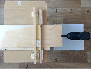
To validate the theoretical results, a laboratory test rig was developed, whose general view is shown in Fig. 3. It consists of a platform (1) capable of translation in the horizontal plane along the -axis and two walls (2, 3). Wall 2 is fixed, whereas wall 3 is mounted to translate along the -axis. A vibration exciter (4) is attached to platform 1. A test body (load) (5) is placed on the platform between the two walls.
Fig. 3General view of the laboratory setup: 1 – platform; 2, 3 – walls; 4 – vibration exciter; 5 – body
In the first stage of the experiments, platform 1 moved at a constant velocity , while wall 3 moved at a constant velocity . The movement of the body in the trough was recorded on video and analysed frame-by-frame. The displacement-measurement error was 0.5 mm. Each test was performed in triplicate. Average velocity was obtained from the measured displacement over a known time interval. The coefficients of friction were measured by the inclined-plane method. Because the kinetic coefficient depends on sliding speed and is difficult to determine accurately, the static and kinetic coefficients were taken equal for the purposes of this study.
In the second stage, using the vibration exciter (4), platform 1 performed harmonic oscillations with velocity , while wall 3 moved at a constant velocity . The exciter frequency was measured with a laser tachometer.
3. Results and discussion
3.1. Results of the theoretical research
As it is shown in theoretical research, when both the platform and the trough walls move at constant velocities, the body’s displacement and velocity vary with time in a manner that depends on the friction coefficients at the platform and wall surfaces (Fig. 4, Fig. 5).
The graphs demonstrate that the body velocity approaches its maximum asymptotically . The platform-body friction coefficient affects only the time required to reach this limit: at 0.2, 95 % of is attained in 0.3 s, whereas at 0.8 the same level is reached in 0.19 s. Clearly, the body velocity cannot exceed the wall velocity.
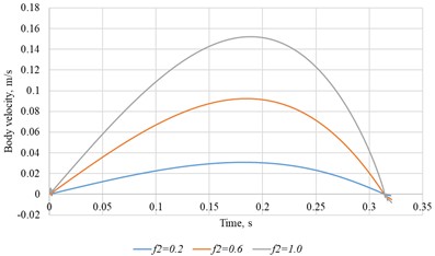
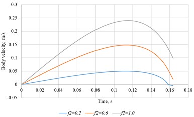
For harmonic platform motion computed velocity-time histories for two amplitudes are shown in Fig. 6.
Fig. 4Body displacement versus time for several values of the friction coefficient between the body and the platform surface (f2= 0.5, V0= 0.3 m/s)
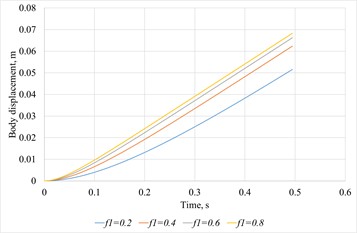
Fig. 5Body velocity versus time for several values of the friction coefficient between the body and the platform surface (f2= 0.5, V0= 0.3 m/s)
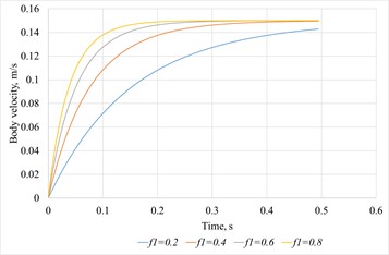
Fig. 6Body velocity versus time for different platform oscillation amplitudes
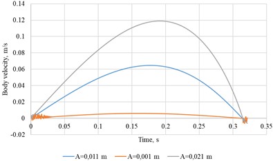
a)0.6, 0.6, = 10 rad/s
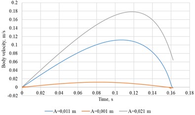
b)0.6, 0.6, = 20 rad/s
The curves indicate a strong dependence of body speed on both platform-oscillation amplitude and frequency. Fig. 7 compares velocity-time responses for several wall-friction coefficients.
Fig. 7Body velocity versus time for different wall-friction coefficients
a)0.011 m, 0.6, = 10 rad/s
b) 0.011 m, 0.6, = 20 rad/s
The peak velocity scales nearly linearly with the wall-friction coefficient, consistent with the constant-velocity regime.
Figs. 8-9 show mean conveying speed versus wall-friction coefficient for multiple platform-friction levels (Fig. 8) and for multiple oscillation amplitudes (Fig. 9).
Fig. 8Average body speed versus wall-friction coefficient for different platform-friction coefficients (A= 0.011 m, ω = 10 rad/s)
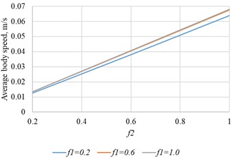
Fig. 9Average body speed versus wall-friction coefficient for different oscillation amplitudes (f1= 0.6, ω = 10 rad/s)
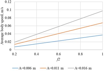
The results show that mean conveying speed is governed mainly by the wall-friction coefficient and platform-oscillation amplitude, with negligible sensitivity to platform-body friction.
Speed rises with amplitude and frequency; however, at = 30 rad/s and 0.02 m. it decreases because within a half-period the body cannot reach its peak velocity. From Fig. 7, doubling platform frequency (from 10 rad/s to 20 rad/s) raises the peak velocity only by 1.6 times, so the growth of the average speed with frequency is sub-linear at higher frequencies.
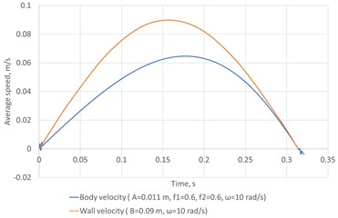
With asymmetric wall oscillations, the body speed cannot exceed the instantaneous wall speed Fig. 10 compares the body and wall velocities.
Fig. 10Body and wall velocities versus time
3.2. Results of the experimental research
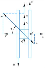
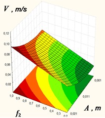
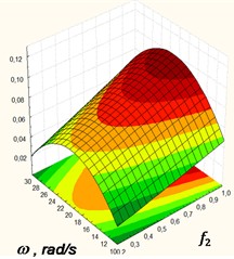
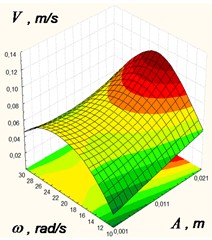
The experimental studies conducted at the laboratory scale plant resulted in obtaining the dependences of an average conveying speed versus oscillation frequency 10 ≤ ≤ 30 (rad/s), amplitude of the platform.0.001 0.021 (rev/m) and friction coefficient between the body and the platform surface 0.2 ≤ ≤ 1 in a technological line, which are presented in the form of response surfaces as a functional а) at = 20 rad/s; b) at = 0.011 m; с) at = 0.6 (Fig. 11).
Analysis of the response-surface sections indicates that the mean speed versus wall-friction coefficient approaches its asymptote . The amplitude and frequency of oscillations exert the dominant influence on the mean conveying speed; notable gains are observed for ≥ 20 rad/s and 0.011 m.
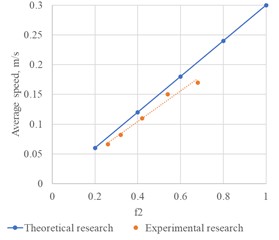
Fig. 12 compares theoretical predictions with experimental data for constant-velocity motion 0.3 m/s and the moving wall at 0.3 m/s.
Under the assumption of equal static and kinetic friction coefficients at all interfaces, theory and experiment agree satisfactorily (error within 14-20 %).
Fig. 11Response surfaces of average conveying speed versus as a functional
а) at = 20 rad/s
b) at 0.011 m
с) at = 0.6
Fig. 12Body velocity versus the coefficient of friction at the surface of the moving wall
4. Conclusions
The study examined body motion in a conveyor trough under constant-velocity travel and harmonic oscillations of the platform. A mathematical model was formulated for these regimes, and numerical integration of the governing equations provided the mean conveying speed as a function of platform and wall kinematics and of the relevant friction coefficients. Experimental results validated the proposed model. The device is suitable for practical implementation, as its conveying speed depends on the oscillation frequency of the platform and walls, which can be adjusted with a frequency inverter. With a stepper-motor drive, both frequency and amplitude are tunable via software control. In the proposed device the body does not undergo transverse oscillations, which reduces energy expenditure for motion perpendicular to the trough axis and, consequently, lowers the required drive power. Upon completion of a full laboratory setup and additional experimental studies, practical guidelines can be formulated for selecting rational design parameters for the proposed vibratory conveyor.
References
-
V. M. Korendii, O. V. Havrylchenko, and V. S. Shenbor, “Vibrating transport and handling conveyors for packaging equipment,” (in Ukrainian), Scientific Journal of the Ternopil National Technical University, Vol. 891, pp. 35–41, 2018.
-
V. Korendiy, O. Kachur, I. Hurey, R. Predko, R. Palash, and O. Havrylchenko, “Modelling and experimental investigation of the vibratory conveyor operating conditions,” Vibroengineering Procedia, Vol. 47, pp. 1–7, Dec. 2022, https://doi.org/10.21595/vp.2022.23057
-
I. I. Blekhman, L. I. Blekhman, L. A. Vaisberg, and V. B. Vasilkov, “Energy performance of vibrational transportation and process machines,” in 14th International Conference on Vibration Problems, pp. 29–46, Dec. 2020, https://doi.org/10.1007/978-981-15-8049-9_2
-
I. Y. Vrublevskyi, “Determination of parameters of two-mass vibratory conveyor with high carrying capacity,” (in Ukrainian), Military Technical Collection, Vol. 21, pp. 3–8, Nov. 2019, https://doi.org/10.33577/2312-4458.21.2019.3-8
-
I. Y. Vrublevsky, “The accuracy of the approximate calculation of elliptical oscillations parameters during the high-speed vibratory conveying,” Military Technical Collection, Vol. 9, pp. 9–12, Nov. 2013, https://doi.org/10.33577/2312-4458.9.2013.9-12
-
M. Popov, V. L. Popov, and N. V. Popov, “Reduction of friction by normal oscillations. I. Influence of contact stiffness,” Friction, Vol. 5, No. 1, pp. 45–55, Mar. 2017, https://doi.org/10.1007/s40544-016-0136-4
-
J. Benad, K. Nakano, V. L. Popov, and M. Popov, “Active control of friction by transverse oscillations,” Friction, Vol. 7, No. 1, pp. 74–85, Mar. 2018, https://doi.org/10.1007/s40544-018-0202-1
-
J. Benad, M. Popov, K. Nakano, and V. L. Popov, “Stiff and soft active control of friction by vibrations and their energy efficiency,” Engineering Research, Vol. 82, No. 4, pp. 331–339, Sep. 2018, https://doi.org/10.1007/s10010-018-0281-1
-
M. Popov, “The influence of vibration on friction: a contact-mechanical perspective,” Frontiers in Mechanical Engineering, Vol. 6, Aug. 2020, https://doi.org/10.3389/fmech.2020.00069
-
R. M. Rohatynsʹkyy, L. S. Serilko, Z. K. Sasyuk, and D. L. Serilko, “Study of the dynamics of inertial conveyors,” (in Ukrainian), Vibrations in Engineering and Technology, Vol. 2, No. 89, pp. 41–48, 2018.
-
L. S. Serilko, O. L. Lyashuk, Z. K. Sasyuk, and D. L. Serilko, “The research of inertial conveyor transitional chute oscillations influence on its technical and economic indicators,” University of Petroșani, Romania, Petrosani, Romania, Jun. 2020.
-
L. Serilko et al., “The dynamics of the inertial conveyor,” International Journal of Engineering Research in Africa, Vol. 72, pp. 35–46, Dec. 2024, https://doi.org/10.4028/p-fiv8k6
-
S. Kilikevičius, A. Fedaravičius, V. Daukantienė, K. Liutkauskienė, and L. Paukštaitis, “Manipulation of miniature and microminiature bodies on a harmonically oscillating platform by controlling dry friction,” Micromachines, Vol. 12, No. 9, p. 1087, Sep. 2021, https://doi.org/10.3390/mi12091087
-
S. Kilikevičius, A. Fedaravičius, V. Daukantienė, and K. Liutkauskienė, “Analysis on conveying of miniature and microparts on a platform subjected to sinusoidal displacement cycles with controlled dry friction,” Mechanics, Vol. 28, No. 1, pp. 38–44, Feb. 2022, https://doi.org/10.5755/j02.mech.28195
-
S. Kilikevičius and A. Fedaravičius, “Vibrational transportation on a platform subjected to sinusoidal displacement cycles employing dry friction control,” Sensors, Vol. 21, No. 21, p. 7280, Nov. 2021, https://doi.org/10.3390/s21217280
-
H. Wijaya, K. Latifi, and Q. Zhou, “Two-dimensional manipulation in mid-air using a single transducer acoustic levitator,” Micromachines, Vol. 10, No. 4, p. 257, Apr. 2019, https://doi.org/10.3390/mi10040257
-
H. X. Cao et al., “Micromotor manipulation using ultrasonic active traveling waves,” Micromachines, Vol. 12, No. 2, p. 192, Feb. 2021, https://doi.org/10.3390/mi12020192
-
O. Lyashuk et al., “The investigation of a physical pendulum motion, which move along a horizontal axis,” Bulletin of the Karaganda University. "Physics" Series, Vol. 106, No. 2, pp. 75–85, Jun. 2022, https://doi.org/10.31489/2022ph1/75-85
-
L. Serilko, O. Lyashuk, D. Chasov, D. Serilko, and R. Ihnatiuk, “Body movement along the surface of an inertial conveyor chute under combined friction,” Journal of Engineering Sciences, Vol. 12, No. 1, pp. D1–D8, Jan. 2025, https://doi.org/10.21272/jes.2025.12(1).d1
-
D. Gelnar, R. Prokeš, L. Jezerska, and J. Zegzulka, “Wood pellets transport with vibrating conveyor: experimental for DEM simulations analysis,” Scientific Reports, Vol. 11, No. 1, p. 11, Aug. 2021, https://doi.org/10.1038/s41598-021-96111-2
About this article

The authors have not disclosed any funding.
The datasets generated during and/or analyzed during the current study are available from the corresponding author on reasonable request.
The authors declare that they have no conflict of interest.
