Abstract
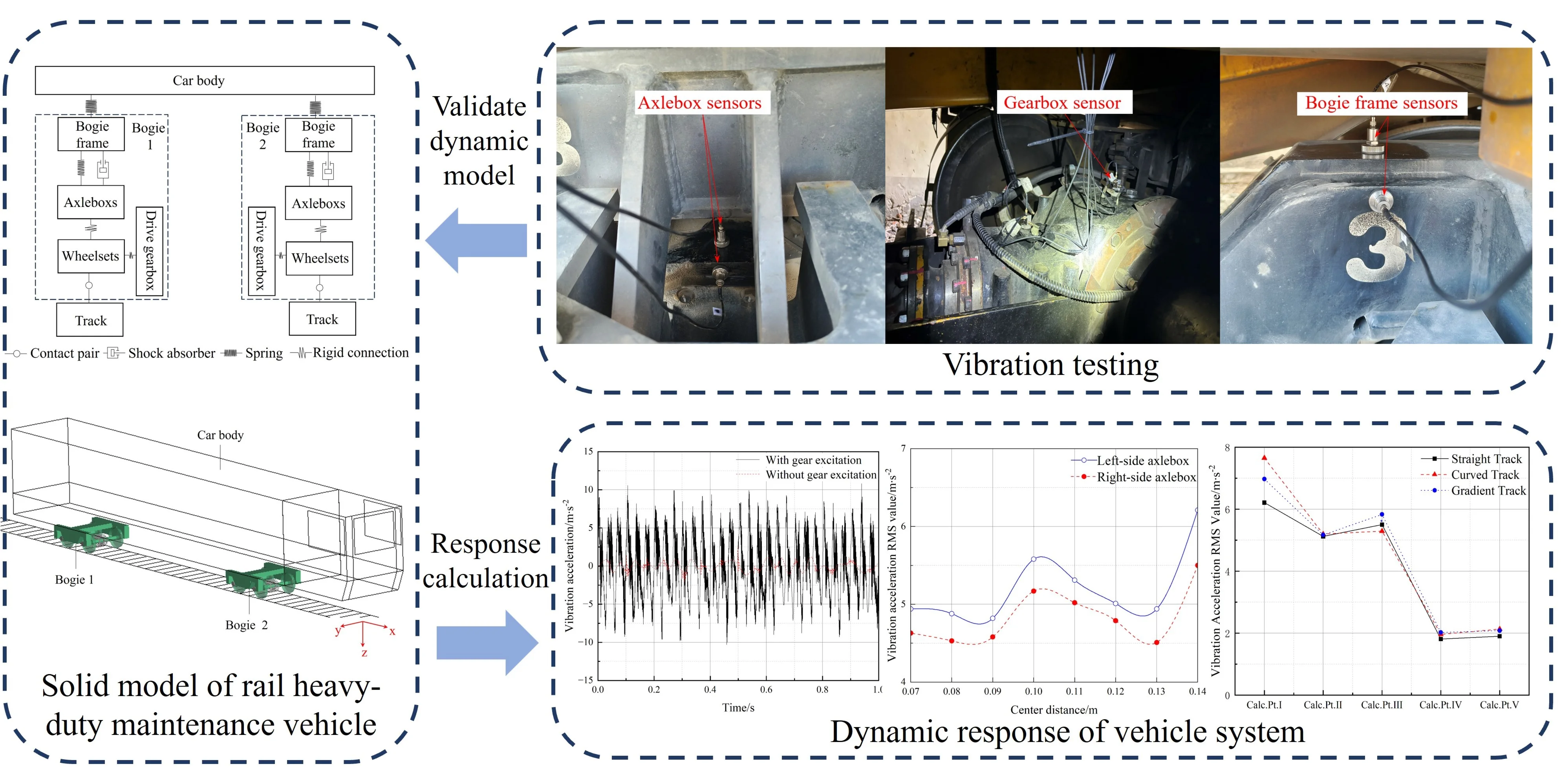
Railway large-scale maintenance vehicles are key equipment for track maintenance. To investigate their dynamic operational characteristics, a dynamics model incorporating multi-rigid-flexible coupling components was developed, and its validity was verified through full-scale vibration tests. The results indicate that: gear system excitation has a significant influence on the vibration characteristics in the -direction and -direction of the vehicle system, so in the dynamic simulation model of heavy-duty maintenance vehicles, gear system excitation load must be considered. As the center distance between the drive gearbox and axle decreases, the root-mean-square value value of vibration of the axleboxes on both sides are reduced, adjusting the center distance while ensuring adequate transmission space of the bogie power axle can effectively control the vibration of the axleboxes on both sides; The vibration response of the left axlebox is always larger than that of other positions under all working conditions, indicating that the side wheel and shaft far from the driving gearbox are more prone to encounter slackness failure induced by dynamic excitation. Therefore, during design stage, it is recommended to increase the axle interference fit.
Highlights
- A multi rigid–flexible coupled dynamic model of a railway large-scale maintenance vehicle with a drive gearbox is established.
- Vibration tests of the railway large-scale maintenance vehicle are carried out to validate the rationality of the proposed model
- The effects of drive gear excitation, drive gearbox arrangement, and operating track conditions on system vibration characteristics are investigated, and improvement measures for vibration and wheel–rail relaxation control are proposed.
1. Introduction
China’s railway industry has experienced rapid development, with the total operational mileage reaching 162,000 kilometers by the end of 2024. Ballast track, as the most predominant form of railway track structure, gradually suffer from performance degradation under the coupling effects of cyclic mechanical loads from trains and complex ambient excitation [1], posing a significant threat to train operation safety. To ensure the safe operation of ballast tracks, regular maintenance by dedicated railway maintenance vehicles is essential.
Rail heavy-duty maintenance vehicles play a vital role in ensuring the safe operation of trains in China [2]. Domestic and foreign scholars have conducted extensive research on railway vehicles. In terms of experimental testing, tests were carried out on the operation process of engineering vehicles to obtain the lateral resistance characteristics of ballast beds [3, 4], and the relationship among sleeper lateral resistance, lateral load and the displacement of track slab were fitted [5]. Based on test data, an optimal operation parameter matching prediction model was constructed [6]. In terms of rigid-flexible coupling models, establishing a coupling model of the stabilizing device and track [7, 8], a dynamic model of flexible bogie for high-speed train [9, 10] and a coupling dynamics model of flexible gearbox and wheelsets [11, 12], analyzing the interaction between the stabilizing device and the rail, the damage of the bogie of high-speed train [13] and the vibration characteristics of drive components [14]. In addition, researchers analyzed the influence of heavy train gear excitation [15-20] and engineering vehicle operation parameters [21] on vehicle and sleeper vibration [22] responses, and investigated the influence of different tamping unit [23, 24] on ballast beds and the track safety after the operation [25].
To sum up, domestic and foreign experts and scholars have conducted extensive research on high-speed trains, heavy trains, and track ballast beds, etc. However, there are few studies on the service characteristics of rail heavy-duty maintenance vehicles, and no in-depth research has been conducted, from the perspective of multi-rigid-flexible coupling dynamics, on the relevance of complex disturbances, such as driving gear drive excitation, track irregularity excitation, and rail line characteristics, to dynamic operation characteristics of rail heavy-duty maintenance vehicles.
Therefore, considering track irregularity excitation, drive system excitation, etc., establishing a multi-rigid-flexible coupling components dynamics model of rail heavy-duty maintenance vehicle, incorporating gear pair, axle, bogie and car body, conducting vibration test on these maintenance vehicles to investigate the influence laws of driving gear, arrangement of driving gearbox, and rail line on system vibrations. This study reveals the dynamic mechanical characteristics of rail heavy-duty maintenance vehicles in service, and provided theoretical support for railway track maintenance and operation.
2. Dynamic modeling of rigid-flexible coupling systems for rail heavy-duty maintenance vehicles
2.1. Rigid-flexible coupling dynamic modeling for rail heavy-duty maintenance vehicles
The stabilizer, as critical equipment in rail heavy-duty maintenance machinery, is shown in Fig. 1(a). During track maintenance, the walking wheels and clamping wheels of the stabilizing device grip the rails, while hydraulic cylinders apply vertical downward pressure to induce overall track sinking. The vibrator generates lateral excitation forces that transmit sequentially through the walking wheel-rail-sleeper-ballast chain. Under external forces, ballast particles gradually compact, increasing ballast bed density and enhancing stability. The stabilization device is illustrated in Fig. 1(b).
Fig. 1Rail heavy-duty maintenance stabilization vehicle. Photo was taken by the author Liu Zhiyang in Chengdu, June 2024
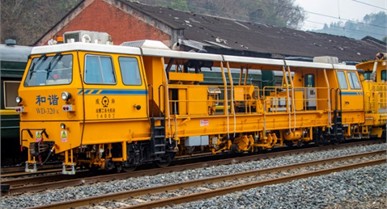
a) Ballast stabilizer
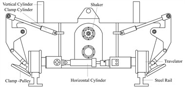
b) Stabilization unit
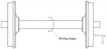
Fig. 2 (a) shows the solid model of the large-size maintenance vehicle, with the bogie illustrated in Fig. 2(b). The bogie primarily consists of 2 wheelsets, 2 traction gearboxes, 4 axleboxes, and a bogie frame. Each wheelset is equipped with 1 traction gearbox and 2 axleboxes. The input gear shaft transmits power through spiral bevel gear meshing to drive the wheelset rotation, propelling the maintenance and stabilization vehicle during operation. The gear system is detailed in Fig. 2(c).
2.2. Multi-body rigid-flexible coupling model for rail heavy-duty maintenance vehicles
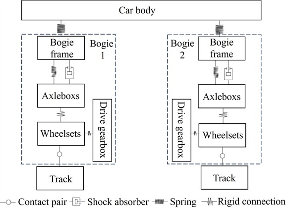
The multibody dynamics model of the large maintenance vehicle was established in SIMPACK, with the connections between components shown in Fig. 3. The wheels and the track are connected through a rolling contact pair. Both ends of the axle are rigidly connected to the axle boxes, with only the rotational degree of freedom about the axle released. The drive gearbox is rigidly connected to the axle, also releasing only its rotational degree of freedom about the axle. The upper part of the gearbox housing is connected to the bogie frame via a stiffness-damping composite unit, which simulates the gearbox suspension device. The meshing of the spiral bevel gear pair inside the gearbox is simulated using a stiffness-damping model. The bogie frame is connected to the axle boxes through hydraulic dampers and rubber springs, and the frame is connected to the car body through the car body springs.
Fig. 2Solid model of rail heavy-duty maintenance vehicle
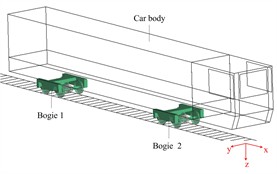
a) Vehicle rigid-body model
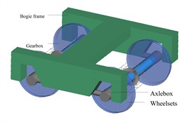
b) Bogie structure
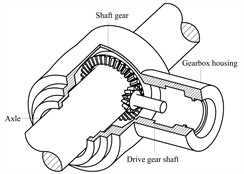
c) Traction gear system
Fig. 3Connection relationships of vehicle main components
Track irregularity excitation based on measured railway track spectra was applied to the simulated track model. Track irregularity excitation is as shown in Fig. 4.
Wheel-rail rolling contact constraints were enforced to ensure continuous wheel-rail kinematic coupling, while a driving torque was applied at the pinion shaft to propel the wheelset. This approach yielded a complete multibody dynamics model of a Rail heavy-duty Maintenance Vehicles, capturing its essential dynamic characteristics.
The structural components, including the bogie frame, wheelsets, and gearbox housing, were discretized into finite element meshes using HYPERMESH software (Fig. 5). Following rigorous mesh quality verification, the resulting mesh models comprised 24,494, 96,816, and 139,621 elements respectively, meeting the convergence criteria for subsequent dynamic analysis.
The yellow reference points indicated in the figure were selected from the flexible models of the bogie frame, wheelset, and gearbox housing to generate flexible substructures via master nodes. These substructures were subsequently imported into SIMPACK to develop flexible-body models of the bogie frame, wheelset, and gearbox housing, which replaced their rigid counterparts. This process ultimately yielded a comprehensive rigid-flexible coupled dynamics model of the rail heavy-duty maintenance vehicles. A comparison of the frequencies of the non-rigid body modes between the reduced substructure of the frame and the finite element model is shown in the Table 1.
Fig. 4Track irregularity excitation
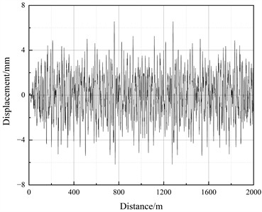
a) Lateral excitation
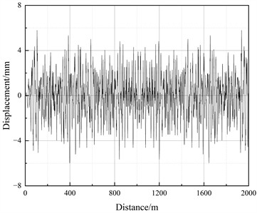
b) Vertical excitation
Fig. 5Meshed finite element model
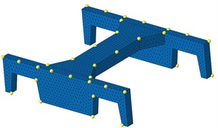
a) Bogie frame
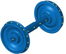
b) Wheelset
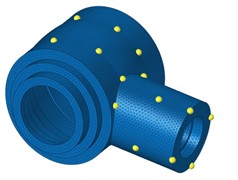
c) Gearbox housing
Table 1Frequencies of the non-rigid body modes
Order | Reduced substructure modal frequency / Hz | Finite element model modal frequency / Hz | Error / % |
1 | 139.98 | 139.31 | 0.48 |
2 | 140.19 | 139.51 | 0.49 |
3 | 268.17 | 266.96 | 0.45 |
4 | 268.95 | 267.75 | 0.45 |
5 | 292.72 | 290.78 | 0.66 |
6 | 294.08 | 292.13 | 0.66 |
As shown in Table 1, the comparison of the elastic modal frequencies between the reduced substructure and the global finite element model shows an error of less than 1 %, demonstrating excellent agreement and validating the applicability of the substructure model for rigid-flexible coupled dynamic simulations.
3. Multi-flexible-body coupling analysis and testing of rail heavy-duty maintenance vehicles
3.1. Multi-flexible-body coupling dynamics analysis
Applying a driving torque at the gearbox input shaft, the large railway maintenance vehicle accelerated from rest to 70 km/h and then maintained at that speed. The simulation torque was set to match the actual motor output torque. The dynamic responses of the gearbox, bogie frame, and axle box were computed using the SIMPACK multibody dynamics software. A schematic of vehicle dynamics analysis points is given in Fig. 6.
Fig. 6Computational points for multi-flexible-body coupled dynamics analysis of the vehicle
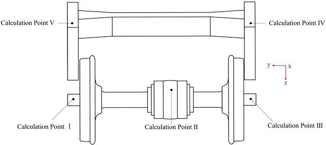
Point I is located on the left axlebox surface, Point II is located on the drive gearbox housing surface, Point III is located on the right axlebox surface, Point IV is located on the right side of the bogie frame, Point V is located on the left side of the bogie frame.
Due to space limitations, only the -direction, -direction, and -direction vibration acceleration responses of Point II (gearbox housing) are presented.
Fig. 7X-direction vibration acceleration response of the gearbox housing
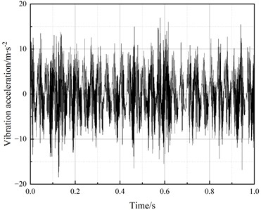
a) Time domain
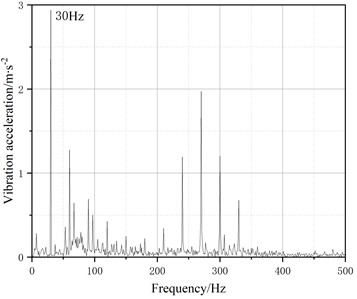
b) Frequency domain
Fig. 8Y-direction vibration acceleration response of the gearbox housing
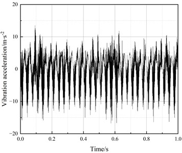
a) Time domain
b) Frequency domain
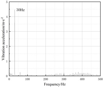
Fig. 9Z-direction vibration acceleration response of the gearbox housing
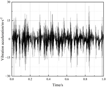
a) Time domain
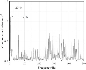
b) Frequency domain
The analysis indicates that among the vibration acceleration responses of the axleboxes, gearbox housing, and bogie frame, The maximum root-mean-square (RMS) value occurs in the -direction of the left axlebox. Both the left axlebox and right side of the bogie frame exhibit higher vertical vibration RMS values compared to their right and left counterparts, respectively; The frequency domain responses of the gearbox housing’s -direction, -direction, and -direction vibration accelerations all contain a dominant 30 Hz component, matching the gear meshing frequency; A 7 Hz spectral component appears in the -direction frequency response of the housing, corresponding to the wheel rotational frequency. This primarily results from significant and asymmetric -direction vibrations between the left and right wheel-axle assemblies, which induce shaft misalignment and consequently generate rotational frequency components.
3.2. Vibration testing and analysis of rail heavy-duty maintenance vehicles
Vibration response testing was conducted at the Chengdu Railway Maintenance Depot in China to validate the multi-flexible-body coupled dynamics model of rail heavy-duty maintenance vehicles. Fig. 10 shows the test point arrangement, where the measurement locations correspond exactly with the computational points.
Fig. 10Measurement point arrangement. These photographs were taken by the author Liu Zhiyang in Chengdu, June 2024
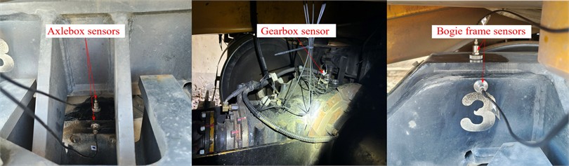
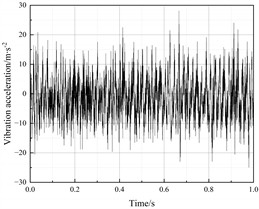
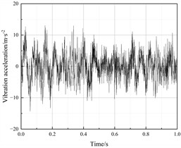
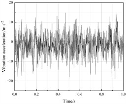
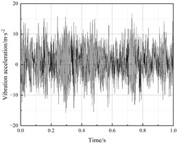
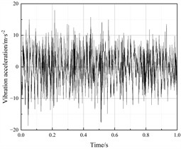
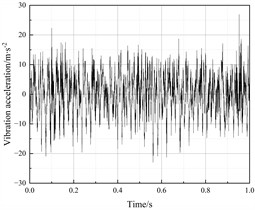
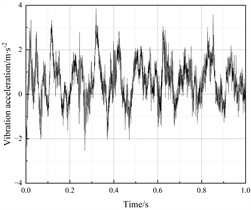
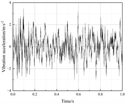
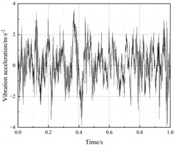
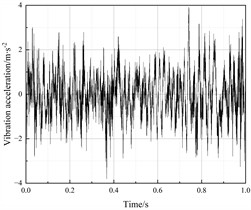
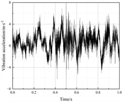
Prior to testing, all measurement points on the large maintenance vehicle were ground and marked. The magnetic bases of the sensors were then placed at each measurement point. During testing, the vibration signals (acceleration vibration signals) measured by the triaxial accelerometers under various working conditions were amplified by a charge-to-voltage filter-integration amplifier. These signals were then fed into an intelligent signal acquisition and processing analyzer for collection. Through the intelligent data acquisition and signal analysis system, vibration acceleration and the frequency spectrum at each measurement point were recorded and analyzed. The tri-directional vibration responses of each measurement point obtained after analysis by the signal analysis system are shown in Figs. 11 to 15.
Fig. 11Vibration acceleration response of the left axlebox (Calculation Point I)
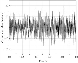
a)-direction
b)-direction
c)-direction
Fig. 12Vibration acceleration response of the gearbox housing (Calculation Point II)
a)-direction
b)-direction
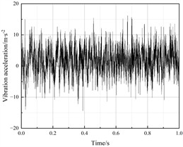
c)-direction
Fig. 13Vibration acceleration response of the right axlebox (Calculation Point Ⅲ)
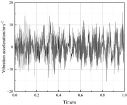
a)-direction
b)-direction
c)-direction
Fig. 14Vibration acceleration response of the bogie frame right side (Calculation Point IV)
a)-direction
b)-direction
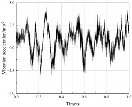
c)-direction
Table 2 presents the comparison between measured and simulated RMS values of vibration responses for the axleboxes, gearbox housing, and bogie frame. The analysis shows that the measured and simulated longitudinal vibration accelerations of the gearbox housing, bogie frame, and axleboxes exhibit good agreement, validating the rationality of the dynamic model. Subsequent analysis will further investigate the influence patterns of drive configuration, load distribution, and operating routes on system vibration characteristics.
Fig. 15Vibration acceleration response of the bogie frame left side (Calculation Point V)
a)-direction
b)-direction
c)-direction
Table 2Comparison of measured and simulated RMS values of vibration responses for calculation points
Calculation Points | Directions | Test value / m∙s-2 | Analysis value / m∙s-2 | Error |
Left axlebox (Calculation Point I) | -direction | 3.53 | 4.01 | 13.60 % |
-direction | 5.49 | 4.73 | 13.84 % | |
-direction | 7.35 | 6.21 | 15.51 % | |
Gearbox housing (Calculation Point II) | -direction | 5.00 | 4.67 | 6.60 % |
-direction | 5.33 | 4.61 | 13.51 % | |
-direction | 4.56 | 5.12 | 10.94 % | |
Right axlebox (Calculation Point III) | -direction | 3.85 | 3.15 | 18.18 % |
-direction | 4.47 | 4.73 | 5.82 % | |
-direction | 7.01 | 5.50 | 21.54 % | |
Bogie frame right side (Calculation Point IV) | -direction | 1.16 | 1.27 | 8.66 % |
-direction | 1.06 | 0.92 | 13.21 % | |
-direction | 1.65 | 1.81 | 9.70 % | |
Bogie frame left side (Calculation Point V) | -direction | 1.04 | 0.96 | 7.69 % |
-direction | 1.08 | 0.90 | 16.67 % | |
-direction | 1.89 | 1.90 | 0.53 % |
4. Dynamic response of vehicle system considering gear drive excitation, gearbox arrangement and track characteristics
4.1. Influence of gear drive excitation on vehicle system vibration characteristics
Study on vibration characteristic variations of vehicle system with/without gear drive excitation based on multi-flexible-body coupling dynamics modeling approach. A model of a heavy-duty Maintenance Vehicle without a gear transmission system was established. Torque was applied around the axial rotation direction at the center of the axle to drive the vehicle forward, as shown in Fig. 16(a). Fig. 16(b) illustrates the traction gear system where torque is transmitted through the meshing action between the input shaft gear and the axle gear to drive the vehicle forward.
Fig. 17 presents the vibration response curve of the left axle box (calculation point Ⅰ) when a vehicle model with or without a gear transmission system is traveling at a constant speed of 70 km/h.
The analysis indicates that the gear excitation has the most significant influence on the -direction and -direction vibration characteristics of the vehicle system. Under the effect of gear excitation, the root-mean-square (RMS) value of -direction vibration acceleration of the left axlebox of the vehicle increased by 591.38 %, the RMS value of -direction vibration acceleration increased by 605.97 %, and the RMS value of -direction vibration acceleration increased by 16.70 %.
Fig. 16Schematic diagram of gearless traction and gear traction
a) Gearless traction
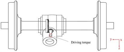
b) Gear traction
Fig. 17Vibration response of the left axlebox (Calculation Point I)
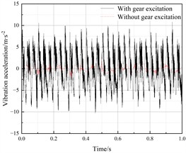
a)-direction
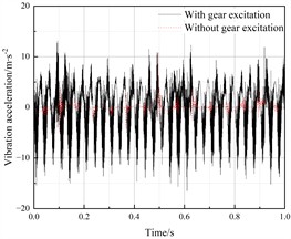
b)-direction
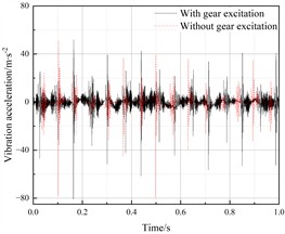
c)-direction
Fig. 18Wheel-rail forces
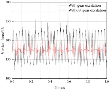
a) Vertical force
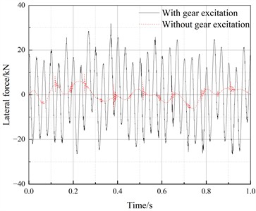
b) Lateral force
Fig. 18 shows the variation of wheel-rail forces with and without gear excitation. The analysis shows that when considering the coupling between gear excitation and flexible gearbox housing vibrations, the wheel-rail vertical force increased by 23.68 %, and the wheel-rail lateral force amplitude increased by 236.79 %; The excitation loads from the gear system should be included in the dynamic simulation model of large-size maintenance vehicles.
4.2. Impact of gearbox arrangement on vehicle system vibration characteristics
By varying the center distance between the gearbox and axle, different drive load distribution conditions were simulated to analyze the variation patterns of vibration responses at both axleboxes. Fig. 19(a) shows a schematic diagram of the center distance between the drive gearbox and axle.
Fig. 19Variation of center distance and bilateral axlebox vibration responses
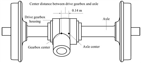
a) The center distance between drive gearbox and axle
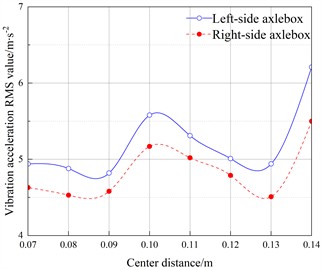
b) Vibration response of both axleboxes
Adjusting the center distance between the drive gearbox and axle, the influence of changes in the center distance between the drive gearbox and axle on the vertical vibration responses of both sides of the axleboxes is analyzed as shown in Fig. 19(b). As the center distance decreases, the RMS values of vibration at both left and right axleboxes will reduce, with a maximum reduction amplitude reaching 20.45 %.
Table 3 presents the root mean square values of the vertical and lateral wheel-rail forces corresponding to different gearbox center distances. Analysis of the table shows that the RMS values of the vertical force exhibit no significant change under different center distances, while the variation trend of the lateral force is consistent with that of the axle box vibration shown in Fig. 20(b), with a maximum reduction of 15.8 %. This indicates that the change in the gearbox position affects the vibration amplitude of the wheelset, which in turn leads to a variation in the contact area between the wheel flange and the rail, ultimately influencing the lateral wheel-rail force. While ensuring the transmission space of the bogie's power axle, reasonably adjusting the center distance between the drive gearbox and axle helps control vibration at both axleboxes.
Table 3RMS values of vertical and lateral wheel-rail forces under different center distance
Center distance / m | Vertical force / kN | Lateral force / kN |
0.07 | 182.09 | 12.89 |
0.08 | 182.08 | 12.73 |
0.09 | 182.10 | 12.49 |
0.10 | 182.26 | 14.43 |
0.11 | 182.11 | 13.59 |
0.12 | 182.15 | 12.15 |
0.13 | 182.09 | 12.60 |
0.14 | 182.27 | 14.41 |
4.3. Influence of operational track characteristics on vehicle system vibration characteristics
To investigate the influence patterns of different operational routes on system vibration characteristics, three types of operating routes were established: a straight line, a curved section with a radius of 1200 m, and a gradient section with a slope of 6 ‰. Fig. 20 presents the RMS values of vibration acceleration responses at various computational points of the vehicle when traveling at constant speed through curved and sloped track sections. Fig. 21 presents the wheel-rail forces as the vehicle passes through different route conditions.
Analysis shows that when the vehicle is traveling uphill, the longitudinal vibration of the drive gearbox housing increases by 4.61 % compared to straight-line operation, the vertical vibration of the left axlebox increases by 10.90 % compared to straight-line operation, and the vertical vibration of the right axlebox increases by 6.00 % compared to straight-line operation; When a vehicle negotiates a left-hand curve, centrifugal force causes the flange of the outer wheel to have increased contact area with the rail, leading to a rise in the lateral force on the wheel. Compared to straight-track operation, the peak lateral force increases by 147.34 %. Concurrently, the vertical vibration of the left-side axle box amplifies by 23.19 %. In contrast, the contact area between the inner wheel flange and the rail diminishes, resulting in a 3.82 % reduction in the vertical vibration of the right-side axle box compared to straight-line travel. The vibration response of the left axlebox (Calculation Point I) is consistently greater than other locations under all operating conditions, indicating that wheels and axles on the side opposite the gearbox are more susceptible to dynamic excitation effects leading to loosening failures, therefore the wheel-axle interference fit should be increased during design.
Fig. 20Vibration responses at vehicle measurement points
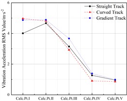
a)-direction
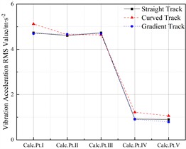
b)-direction
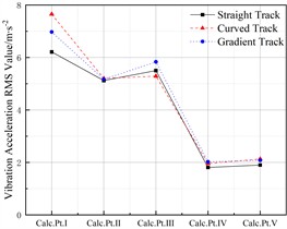
c)-direction
Fig. 21Wheel-rail forces under different route conditions
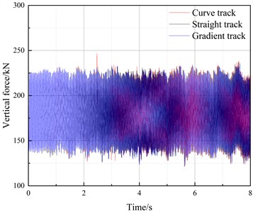
a) Vertical force
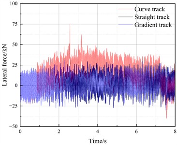
b) Lateral force
5. Conclusions
1) A multi-flexible-body coupled dynamics model for railway large-size maintenance vehicles was established, and the rationality of the dynamic model was verified through comparative analysis between experimental test data and simulation results, demonstrating that this model can be effectively applied to analyze the vibration characteristics of vehicle systems.
2) Under gear excitation conditions, the RMS values of -direction and -direction vibration accelerations at the vehicle’s left axlebox increased by 591.38 % and 605.97 % respectively, while the peak values of wheel-rail vertical and lateral forces increased by 23.68 % and 236.79 % respectively. These results demonstrate that gear system excitation loads must be included in the dynamic simulation models of large-size maintenance vehicles.
3) Under gear excitation conditions, the RMS values of -direction and -direction vibration accelerations at the vehicle’s left axlebox increased by 591.38 % and 605.97 % respectively, while the peak values of wheel-rail vertical and lateral forces increased by 23.68 % and 236.79 % respectively. These results demonstrate that gear system excitation loads must be included in the dynamic simulation models of large-size maintenance vehicles.
4) Compared to straight-line operation, when the vehicle is traveling uphill, the -direction vibration of the drive gearbox housing increases by 4.61 %, while the -direction vibrations of the left and right axleboxes increase by 10.90 % and 6.00 % respectively; during curve negotiation, the -direction vibration of the outer-side (left) axlebox increases by 23.19 %, whereas the -direction vibration of the inner-side (right) axlebox decreases by 3.82 %. The vibration response of the left axlebox remains greater than other locations under all operating conditions, indicating that wheels and axles on the side opposite the gearbox are more susceptible to dynamic excitation effects leading to loosening failures. Therefore, the wheel-axle interference fit should be increased during design.
References
-
G. Liang, X. Yang, and G. T. Yang, “Review of research of railway ballast bed deterioration,” (in Chinese), Journal of the China Railway Society, Vol. 44, No. 8, pp. 78–92, 2022, https://doi.org/10.3969/j.issn.1001-8360.2022.08.009
-
D. Mu et al., “Effect of track comprehensive maintenance on geometry irregularity improvement of ballast track in high-speed railway,” (in Chinese), Journal of Traffic and Transportation Engineering, Vol. 18, No. 5, pp. 90–99, 2018, https://doi.org/10.19818/j.cnki.1671-1637.2018.05.009
-
W. Koc, A. Wilk, P. Chrostowski, and S. Grulkowski, “Tests on lateral resistance in railway tracks during the operation of a tamping machine,” Proceedings of the Institution of Mechanical Engineers, Part F: Journal of Rail and Rapid Transit, Vol. 225, No. 3, pp. 325–340, Apr. 2011, https://doi.org/10.1243/09544097jrrt324
-
W. Koc, A. Wilk, P. Chrostowski, and S. Grulkowski, “Determination of the transverse resistance characteristics in railway track,” Journal of Transportation Engineering, Vol. 136, No. 12, pp. 1057–1067, Dec. 2010, https://doi.org/10.1061/(asce)te.1943-5436.0000167
-
C. J. Chen and H. Jiang, “Experimental research on response characteristics of track panel under stabilizer-track coupling,” (in Chinese), Journal of Railway Science and Engineering, Vol. 21, No. 7, pp. 2699–2706, 2024, https://doi.org/10.19713/j.cnki.43-1423/u.t20231607
-
B. Yan, B. Hu, and Y. Huang, “Prediction model with optimal matching parameters for a dynamic track stabiliser during railway maintenance,” International Journal of Modelling, Identification and Control, Vol. 33, No. 4, pp. 369–377, Jan. 2019, https://doi.org/10.1504/ijmic.2019.107485
-
M. Lin, C. Chen, J. Deng, and H. Qin, “Dynamic modelling and experimental validation of a dynamic track stabiliser vehicle-track spatially coupling dynamics system,” Proceedings of the Institution of Mechanical Engineers, Part K: Journal of Multi-body Dynamics, Vol. 238, No. 3, pp. 480–503, Aug. 2024, https://doi.org/10.1177/14644193241271763
-
Q. Wang, X. Wu, S. Z. Li, and X. Pei, “Dynamic characteristics of stabilizing device-ballasted rail coupling system of force stabilized vehicle,” (in Chinese), Machinery Design and Manufacture, No. 7, pp. 103–110, 2024, https://doi.org/10.19356/j.cnki.1001-3997.20240322.010
-
Y. Han, W. Shi, and W. Feng, “Dynamic damage detection and assessment on the bogie frame of high-speed train based on the coupled elastic and multibody dynamics scheme,” Acta Mechanica Solida Sinica, Vol. 36, No. 5, pp. 633–646, Jul. 2023, https://doi.org/10.1007/s10338-023-00410-2
-
Y. Lu, P. Xiang, P. Dong, X. Zhang, and J. Zeng, “Analysis of the effects of vibration modes on fatigue damage in high-speed train bogie frames,” Engineering Failure Analysis, Vol. 89, pp. 222–241, Jul. 2018, https://doi.org/10.1016/j.engfailanal.2018.02.025
-
S. Bruni, J. Vinolas, M. Berg, O. Polach, and S. Stichel, “Modelling of suspension components in a rail vehicle dynamics context,” Vehicle System Dynamics, Vol. 49, No. 7, pp. 1021–1072, Jul. 2011, https://doi.org/10.1080/00423114.2011.586430
-
H. Y. Zhu et al., “Influence of suspension parameters of traction motor on vibration characteristics of traction drive components of high-speed train,” (in Chinese), Journal of Traffic and Transportation Engineering, Vol. 23, No. 1, pp. 156–169, 2023, https://doi.org/10.19818/j.cnki.1671-1637.2023.01.012
-
Y. Han, D. Crosbee, P. Allen, W. Feng, R. Wang, and J. Yu, “Dynamic fatigue damage calculation for a high-speed train bogie frame considering the three-dimensional gear meshing,” Vehicle System Dynamics, Vol. 63, No. 9, pp. 1790–1809, Sep. 2025, https://doi.org/10.1080/00423114.2024.2384062
-
Z. Wang, Y. Cheng, P. Allen, Z. Yin, D. Zou, and W. Zhang, “Analysis of vibration and temperature on the axle box bearing of a high-speed train,” Vehicle System Dynamics, Vol. 58, No. 10, pp. 1605–1628, Oct. 2020, https://doi.org/10.1080/00423114.2019.1645340
-
S. Ebrahimi and P. Eberhard, “Rigid-elastic modeling of meshing gear wheels in multibody systems,” Multibody System Dynamics, Vol. 16, No. 1, pp. 55–71, Jul. 2006, https://doi.org/10.1007/s11044-006-9021-7
-
Z. Wang, W. Zhang, Z. Yin, Y. Cheng, G. Huang, and H. Zou, “Effect of vehicle vibration environment of high-speed train on dynamic performance of axle box bearing,” Vehicle System Dynamics, Vol. 57, No. 4, pp. 543–563, Apr. 2019, https://doi.org/10.1080/00423114.2018.1473615
-
Z. Ren, X. Xin, G. Sun, and X. Wei, “The effect of gear meshing on the high-speed vehicle dynamics,” Vehicle System Dynamics, Vol. 59, No. 5, pp. 743–764, May 2021, https://doi.org/10.1080/00423114.2020.1711955
-
S. Gang, R. Zunsong, X. Xin, and W. Xue, “Dynamics of gear transmission system of high-speed vehicle,” Journal of Mechanical Engineering, Vol. 55, No. 18, p. 104, Jan. 2019, https://doi.org/10.3901/jme.2019.18.104
-
Z. Chen, W. Zhai, and K. Wang, “Dynamic investigation of a locomotive with effect of gear transmissions under tractive conditions,” Journal of Sound and Vibration, Vol. 408, pp. 220–233, Nov. 2017, https://doi.org/10.1016/j.jsv.2017.07.017
-
G.-H. Huang, N. Zhou, and W.-H. Zhang, “Effect of internal dynamic excitation of the traction system on the dynamic behavior of a high-speed train,” Proceedings of the Institution of Mechanical Engineers, Part F: Journal of Rail and Rapid Transit, Vol. 230, No. 8, pp. 1899–1907, Aug. 2016, https://doi.org/10.1177/0954409715617787
-
J. M. Chen, L. H. Wang, and X. H. Su, “Lateral dynamic characterization of power stabilized vehicle-roadbed-bridge system,” (in Chinese), Railway Standard Design, Vol. 65, No. 9, pp. 84–88, 2021, https://doi.org/10.13238/j.issn.1004-2954.202007280004
-
L. A. Yang, W. Powrie, and J. A. Priest, “Dynamic stress analysis of a ballasted railway track bed during train passage,” Journal of Geotechnical and Geoenvironmental Engineering, Vol. 135, No. 5, pp. 680–689, May 2009, https://doi.org/10.1061/(asce)gt.1943-5606.0000032
-
Z. X. Qian et al., “Research on the effect of impact type artificial tamping device on ballasted bed and its quality status,” Journal of the China Railway Society, Vol. 46, No. 3, pp. 155–164, 2024.
-
Z. H. Zhang et al., “Experimental study on vibration transmission and attenuation characteristics of ballasted track under the excitation of three-pillow tamping device,” Journal of the China Railway Society, Vol. 46, No. 3, pp. 21–31, 2024.
-
A. Abbasi, J. A. Zakeri, E. Norouzi, and S. A. Mosayebi, “Field investigation on the effect of the tamping machine and dynamic track stabilizer on changing the rail support modulus,” Proceedings of the Institution of Mechanical Engineers, Part F: Journal of Rail and Rapid Transit, Vol. 238, No. 9, pp. 1072–1083, May 2024, https://doi.org/10.1177/09544097241255718
About this article

This work was supported by the research project of Chongqing Jiaotong University (cqjt-zk-2023-301).
The datasets generated during and/or analyzed during the current study are available from the corresponding author on reasonable request.
Zhiyang Liu: investigation, writing - original draft preparation, visualization, methodology. Zeyin He: conceptualization, funding acquisition, supervision, project administration. Runjie Duan: investigation. Junjie Yang: resources. Gaohua Hu: resources.
The authors declare that they have no conflict of interest.
