Abstract
Current helicopter onboard monitoring systems are not effective enough, and most helicopters do not even have them. As helicopter unit state is not clearly known, it is subject of preventive maintenance. To maintain helicopters predictively reducing repair costs and time, the techniques are required that allow diagnosing the operating units in field conditions for all helicopters. This work is aimed to practically check the Vibropassport techniques allowing the predictive maintenance on the operating helicopter. The Vibropassport using high-order models considers the spatial vibrations in a wide frequency range, applies diagnostic parameters at the normalized scale, and allows diagnostics using a single field inspection. The main finding of the work is that the Vibropassport-based system adapted to a specific helicopter type allows the detailed diagnostics of the engines, gearboxes and transmissions based on the data of a single test in field conditions. Applicability of the Vibropassport system in field conditions was demonstrated on an operating helicopter, and the vibration-based diagnostics estimates whether the unit state complies with the thresholds common for a wide range of similar units. The Vibropassport-based system makes the predictive maintenance possible, reducing costs of maintenance and repair for helicopters, including those without onboard monitoring systems.
Highlights
- Methodology for vibration diagnosing of helicopter rotating units in a single field inspection
- Prototype of compact and portable diagnostic system for field use
- Successful field trial of the system on the medium heavy helicopter
- Using 190 diagnostic parameters, the condition of critical engine, main gearbox, and transmission components was assessed
1. Introduction
Sustainability and economic efficiency of helicopter operations depend on the concept of technical maintenance and repair. Basically, two concepts are considered: preventive and predictive maintenance [1]. Preventive maintenance is performed at predetermined intervals regardless of the technical condition. Predictive maintenance is considered more efficient due to the reduced downtime, which in its turn results in lower maintenance and repair costs and increased revenue. Predictive maintenance is a technique that uses condition monitoring tools and methods to support the performance of equipment during operation [2]. For most helicopters, the airworthiness is maintained through preventive maintenance and repair methods. The technical state of repaired units affects the logistics of spare parts required for overhaul, as well as the volume and timing of repair works. Currently, the state of units becomes known after disassembling the helicopter in a workshop. It is one of the reasons why MRO-industry service providers lack suitable and applicable approaches to the spare parts demand forecasting [3]. The period between the decision to send a helicopter for overhaul and the completion of defect detection can take several months. To reduce time and cost of an overhaul, the technical state of helicopter rotating units must be assessed in the field before sending the helicopter to a workshop. To provide a predictive approach, a maintenance and repair operator must interact with the diagnostic system that covers all units of helicopter. The higher resolution of diagnostic techniques for detecting hidden and developing defects is, the more accurate predicting of the technical condition will be. Currently, only a few of helicopters have on-board systems that are controlled by different operators: engine modules [4] provide data to the manufacturer only, the data of drive train monitoring system [5] may be available to the operator. The helicopter structures are inspected during the manufacturing process only by non-destructive techniques [6].
Actually, in helicopters, there are only separate board monitoring systems for engines and drive train [7]. Engines condition is estimated using on-board condition monitoring units (CMU) that measure vibrations along with other parameters and are supervised by manufacturer [4]. The CMU performance is limited to a rotor vibration monitoring (within the frequency band of 1-2 kHz) and is sensitive mainly to large defects that can increase the rotor vibration. For instance, the GE Aerospace monitors the engine condition by parameters of oil temperature and pressure, fuel consumption and vibration during rotation [8]. The limited functionality of actual CMU leaves critical engine units unattended, including gear drives, as well as the flow path of the compressor and turbine. There are new engine monitoring units (EMU) [9] and additional modules for vibration monitoring of specific bearings [10] that are used for turbofans only, however, no such units are provided for helicopter engines. At the same time, most typical defects of aircraft engines, including damages of blades and guide vanes, gears and bearings, remain outside the field of view of these systems. Many works are dedicated to investigate the most efficient jet engine vibration diagnostics, especially for the most complicated parts as flow duct aggregates, gearbox and bearings.
The influence of blade-off damage on the deterministic part of vibration structure was researched, where the aerodynamic vibration is simplified as harmonics at the blade meshing frequencies [11]. The energy of mechanic and aerodynamic excitations in compressor or turbine stage was estimated aiming at cracking prevention as well as the amplitudes of vibration and acoustic harmonics of passing frequencies were also measured at the shaft and blade [12]. The above approaches may be effective in monitoring, where a diagnostic decision can be made using a long-term observation only. To be predictive, the diagnostic system must be capable of quantitatively assessing the condition of critical helicopter rotating units based on single inspection. Unlike in above mentioned, the diagnostic platform of Vibropassport uses a more realistic aerodynamic vibration model with deterministic and random components [13]. The model considers vibrations as a feedback of a peripherally located sensor to the excitation of spatially distributed guide vanes to rotating blade wakes. The novel diagnostic parameters (DPs) of compressor stages were experimentally validated for jet engines.
To improve the diagnostic algorithms of engine gears, the research of progressive tooth wear on vibration structure was undertaken in [14]. The simulated vibration responses and experimental validation show that the wear increases in the amplitudes of the gear mesh frequency and its harmonics. Earlier in [15], the authors presented a new model of gear vibration that allowed considering the influence of bearing transfer features, which distorted gear vibrations measurement taken by the sensor on a casing. Based on this model, a diagnostic technique for gearbox teeth was experimentally substantiated, allowing for a quantitative assessment of defects.
The rotor bearings are too complicated for a comprehend diagnostics as many powerful sources of jet engines mask bearing vibrations. As concluded in [16], the monitoring of rolling bearing is possible only on the bearing house comparing vibration amplitudes with bearing frequencies. This approach is not applicable to helicopter engines, where access to the bearing housing is impossible. In [17], the model of bearing vibration considering the operating bearing as the transfer function, not as an independent vibration source was formulated and validated. Based on this model, the new adaptive technique was experimentally validated that used the normalized scale of DPs common for a wide variety of bearing types.
The drive train of helicopters is monitored better using the HUMS (Health and Usage Monitoring System) or VMS (Vibration monitoring Systems) [18, 19]. The systems, like HUMS, are used for monitoring different parameters on top of vibration amplitudes. This allows damage detection of a drive train, including bearings, shaft and tail gearbox. However, other critical units, like main and tail rotors or planetary stages of a main gearbox remain out of control [20]. For helicopter units that are not covered by vibration monitoring, the flight hours are used, as a criteria of technical state worsening, like in [21]. Since the condition of helicopter units depends on operating conditions [22] and individual specialties, the “usage” criteria is inaccurate and may lead to mistakes, like false alarm or missed target. As defects in planetary gears of main gearbox are most dangerous for safe helicopter flight, some researchers work on their identification. For example, advance dimensionless indices are used based on a simplified model of vibration components within the predetermined frequency range [23]. The lack of an adequate vibration model does not allow substantiating the reliable DPs despite the modern methods of signal processing. The dedicated vibration model, as in [24], takes into account the planets rotation and the vibration paths alternation in planetary gears. This allows to relate the increase of vibrations on model-based frequencies with seeded faults. However, these values as DPs are not effective as they depend on the operating mode and vary in time. The varying external load is considered, as this factor essentially influence vibration and may mask the damage indices [25]. The detailed consideration of micro and macro geometric factors, material properties, operating conditions, and the influence of bearings led the authors to use for diagnosing both vibration meshing components and white noise of bearings. For this purpose, the coherence gearbox condition monitoring method was developed. Though the latter allows better evaluating the gear condition, the deterministic component of bearings influence is underestimated. Based on the experimental research, vibration of epicyclical gears was considered as the complex product of random bearing vibrations modulated as per the simulation of gear elements rotation and deterministic interactions of gears [26]. DPs of Vibropassport based on the above model use the normalized scale and do not operate with vibration amplitudes.
Common disadvantage of most on-board vibration monitoring systems is the use of absolute values of vibrations as DPs. As vibrations depends on the operating mode and is different in each individual unit, the amplitudes as diagnostic parameter have limited effectiveness. Resuming, the existing board monitoring systems allow reducing flight accidents but cannot fully support the predictive maintenance of helicopters. An even bigger obstacle to predictive maintenance is that most helicopters do not have an on-board monitoring system, even if it is not very effective.
Unlike in other approaches, the DPs of Vibropassport here have normalized scales that are common for most rotating units of any engine type, including bearings, gears, compressor stages, etc. To make vibration diagnostics predictive, two experimentally validated novelties were combined. First, the set of advanced techniques was created based on high-order vibration models that provides DPs in normalized scale. Second, the “passport” approach that allows diagnosing the particular helicopter using one-time inspection without long data accumulation was applied. The vibration diagnostics based on single inspection in field may accelerate the transition to predictive maintenance, and it is an alternative to traditional condition monitoring tools and techniques, discussed earlier. This approach does not require an onboard system and repeated observations. Aiming at cost and time saving, the inspection should be time-limited and without participation of manufacturer representatives, whose invitation takes a long time and is not cheap.
The aim of the work is to test in practice the ability of the Vibropassport to diagnose helicopter rotating units based on a one-time inspection and to check applicability of the system prototype in an operating helicopter. The practical tasks of the study consist in adapting the Vibropassport algorithms to the specific type of helicopter, prototyping the system for a specific helicopter type and trial application of the system on an operating helicopter. The analysis of the Vibropassport techniques, required measurement system, description of the system prototype and the trial application are considered in Section 2 (Method and Materials). Discussion of the results of trial application is present in Section 3 (Discussions) and Conclusions are in Section 4.
2. Vibropassport-based system
The system capable for a single-inspection vibration diagnostic of a helicopter has three virtual dimensions: intellectual, measuring and methodical. The intellectual dimension is presented by Vibropassport, which includes vibration models of typical rotating units, algorithms of data development and DPs computation in the software for the above-mentioned result. The measured part includes vibration sensors and the equipment for signal measurement and recording. The methodical part covers the practical issues of the system application, including measurement methods, sensors locations and mounting, and the influence of helicopter operating modes.
2.1. Vibropassport
2.1.1. Concept
Vibropassport is a methodical and software platform for diagnosing the rotating units. The DPs, calculated using vibration and phase signals of the particular operating units, are compared with the thresholds common to all units of the same type. The Vibropassport is structurally implemented in three levels, which are illustrated by the diagram in Fig. 1.
Fig. 1Levels of Vibropassport
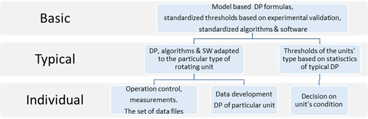
The basic level contains the model-based DPs, each of which characterizes one of the aspects of the rotating unit operation. At this level, DPs of the Vibropassport are expressed as standardized formulas, which arguments cover the vibration components related to the model. Based on the results of experimental validation of vibration models, each DP at this level has the model-based normalized scale with indicated threshold limiting the distribution area in a healthy or faulty state.
At the typical level, the arguments of the DP calculation formulas are adopted to the design of a rotating unit type, such as the number of turbine blades or gear teeth. The adopted DPs, their thresholds, and the software implementing the calculation algorithms become common (typical) to all rotating units of same type. Since the operating mode affects the DP, the typical Vibropassport also defines the unit operating modes, at which the vibration signals are used.
The individual level refers to a specific unit, which condition is assessed with the DP calculated using the typical formula and signals of the specific unit. Condition of the rotating unit in the considered approach is estimated as comparing with the DP value obtained as a result of one-time inspection with the typical threshold (common to all units of this type).
2.1.2. Vibration models
The vibration models of rotating units are the core of Vibropassport. General kinds of rotating units are rolling bearings and gears located in the helicopter drive train, while in a jet engine there are also stages of a compressor, turbine, and a combustion chamber. The models of Vibropassport describe both the nature of dynamic interactions, similar for general units, and the vibration paths in different machines. Taking both into account, it is possible to model the damage or abnormal functioning of a unit, predicting the vibration changes in frequency, time or spatial domains. The models are presented in a wide frequency range due to the pulse nature of most interactions and to a high rotation speed in a helicopter engine.
For example, a wake pulse produced by a rotating blade impacting a downstream guide vane persists for several tenths of a millisecond; consequently, in the frequency domain, this excitation manifests as a spectral band within the tens-of-kilohertz range.
Moreover, the vibration model of compressor stage considers a wide frequency band of the transfer properties of vibration paths from the guide vane to the sensor [27]. Therefore, Vibropassport models account for an expanded frequency range exceeding 20 kHz. This allows considering both the deterministic component of dynamic interactions associated with the periodic processes, and a random part caused by a non-stationarity of interactions. For example, the equation that simulates the aerodynamically induced vibrations in [13] describes the train of vibration pulses as a response of spatially distributed guide vanes to aerodynamic excitations during one rotor revolution. The model incorporates design properties (blade/vane number, their irregularities and housing anisotropy) as well as operating parameters, including the upstream flow profile and rotation speed.
The gear vibration model presented mathematically in [15] also considers the casing response to impulse excitations induced by gear-teeth meshing and modulated by their irregularities. The model also considers the influence of bearings in the vibration path between the gear and the sensor.
The epicyclical gears of the helicopter main gearbox are the most complicated thing to be diagnosed. Based on the time-spatial model [26], the deterministic components of epicyclical gear vibration isolated in the time domain are applied for the DPs calculation. Depending on a frequency range available for signal processing, the two techniques are applied as follows: the traditional Time Synchronized Averaging and the original Spatial Time Domain Distribution.
The bearing vibration model [17] considers the casing response to the random process modulated by quasi-periodical processes. The random component is generated by the balls or rollers moving over an uneven surface, while the rotor precession is responsible for quasi-periodical processes. The main provisions of the Vibropassport models have been validated using our own experimental test rigs for bearings, gearboxes, compressor stages and combustion chamber.
2.1.3. Diagnostic parameters and thresholds
Vibropassport makes the complete diagnostics of the helicopter rotating units by using standardized DPs. Each DP characterizes a specific aspect of unit operation using the ratio of typical vibration components that are close for similar units. For example, for a compressor stage, two kinds of vibration components are typical. The deterministic ones are related to the rotor speed multiplied by the number of rotating blades. The random components are caused by the flow non-stationarity in the zone of blade wakes. Due to the general principles of compressor operation, the DPs of compressor stage are common for most types of helicopter engines. For example, the DP of flow non-stationarity in a compressor evaluates the relation between the deterministic and random vibration components. The first one is determined by the number of blades in the stage, and the second is formed by flow separations in blade wakes that depend on an operating mode. The Vibropassport for state evaluation uses dimensionless DPs, rather than absolute vibration levels. The relative scale of the DP is formed by the relationship between the vibration components, which, according to the model, are associated with the state of the rotating unit.
For most DPs of the Vibropassport (except for the flow non-stationarity one), the zero point of the normalized scale corresponds to the ideal state of the unit. Any DP increase from zero means worsening of the unit functionality. As any rotating unit is not ideal, the serviceable unit state corresponds to the area of small positive values. The general DP threshold of a healthy unit is indicated using the statistics of healthy operating units. The DP values corresponding to a specific type of defect are estimated experimentally. There are two kinds of normalized scales (Fig. 2).
In the normalized Teeth Diagnostic Parameter (TDP) scale (Fig. 2(a)), the serviceable state of the pinion-gearwheel gearing corresponds to the range from 0 to 0.5 ... 0.6. An increase to 1.0 and more indicates the appearance and following development of a defect. The specified threshold zone was determined in a study conducted on the specialized experimental setup [15]. The Non-Stationarity Diagnostic Parameter (NSP) of flow non-stationarity in a compressor stage has other kind of normalized scale illustrated in (Fig. 2(b)). On the correlation-based scale, a value of 1.0 corresponds to an ideal flow, whereas values approaching 0 or below indicate greater flow unsteadiness.
The main benefit of the normalized scale is its ability to extrapolate the threshold values obtained from experimentally studied units to other units with similar design. The universality of the normalized scale for similar types of rotating units allows using common thresholds for preliminary diagnosis of the unit which vibrations have not yet been measured. In practice, general thresholds are applied at the initial stage of Vibropassport implementation. After accumulating statistical data on the DP of a specific type of unit, the thresholds are corrected and become type-specific one.
Fig. 2Normalized scales of DPs
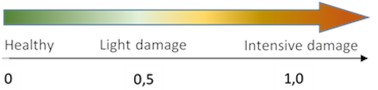
a) TDP
b) NSP
2.1.4. Algorithms
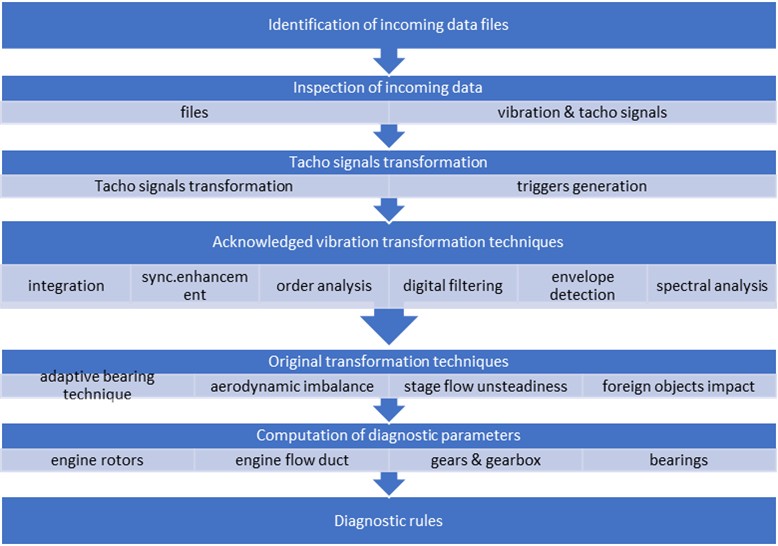
The standardized algorithms of the Vibropassport cover the entire data processing cycle, from signal conditioning to diagnostic decision-making. The hierarchy of algorithms implementing the Vibropassport techniques for a one-time helicopter inspection is illustrated in Fig. 3 and 4.
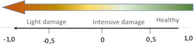
Fig. 3Algorithms of helicopter signal registration
Fig. 3 shows the algorithms responsible for controlling the vibration and rotation signal registration during helicopter testing. To verify the measurement channels, the system operator interacts with the technician whereas the test initialization requires coordination with the pilot. After the engines are started, the system monitors the crew completion of the test program. The program involves testing the helicopter in fixed operating modes that provide comparable loads on the main units, regardless of environmental conditions such as temperature.
When an operation mode specified in the test program is achieved, the system monitors the signals and records them. After the registration is complete, the system identifies the data files and saves them in the test database. Data processing and diagnostics of the helicopter unit condition can be performed in-situ after testing or remotely in the laboratory, where the data can be transmitted.
Fig. 4 shows the sequence of Vibropassport algorithms that ensure automatic data processing and diagnostics of the rotating units. First, the algorithms inspect the raw data files including the compliance with the requirements for data format and file sizes, and the quality of the vibration and rotation signals. Then, the algorithms develop the rotation (phase) signals of the engine and gearbox forming the trigger arrays for the vibration signal processing. For processing the vibration signals, both generally acknowledged algorithms and original ones are applied. The first ones implement the methods of integration, time synchronous averaging (TSA), order analysis, digital filtering, envelope and spectral analysis that are widely used in processing the dynamic signals. The Vibropassport also applies the original algorithms that have been validated during the specialized experimental setups. For instance, the adaptive method for bearings diagnosing provides diagnostic estimates of races (inner and outer), rollers/balls, and radial gap. Another example is the set of original algorithms for jet engines, including the geared drives, the assessment of aerodynamic unbalance and stability margin of compressor stages and the detection of foreign objects. Both types of algorithms provide for the extraction of proper components indicating a change in the unit state, and suppress vibration noise. The latter is important for a helicopter, where main and tail rotors are powerful sources inducing vibrations in engines, main gearbox and drive train. When the particular unit is diagnosed, these induced vibrations may play role of “noise”. For vibration noise isolation, the TSA techniques are used for deterministic components, and digital filtering is applied for quasi-deterministic and random ones.
The DPs calculated using the above components are the primary signs of the state of engines, gearboxes and drive train. At the final stage, the diagnostic rules substantiate a decision on the serviceability of each helicopter unit.
Fig. 4Hierarchy of Vibropassport algorithms
2.1.5. Vibropassport adaptation
For diagnosing the specific type of unit, the formulas of standardized DPs and the algorithms for its calculation must be adapted to the design and operating modes of the specific helicopter type. As an object for vibration diagnostic system prototyping, the widely used middle-class helicopter (MCH) was chosen whose design data is publicly available.
Vibropassport adaptation to the helicopter type is carried out in two stages. First stage starts with an analysis of each unit design and results in a set of standardized DPs, like in Table 1, including engines, main gearbox and drive train. Totally, Vibropassport of MCH uses 190 DPs to assess the condition of the helicopter power plant units. There are 60 parameters for diagnosing each of two engines, 22 DPs for the main gearbox and 48 for the drive train. Each DP listed in the table is obtained by “tuning” a standardized parameter to the design and operating frequency range of the unit type.
Table 1Standardized DPs of helicopter power units
Row No | Aggregate | Unit | DP name | Stage | DP quantity |
1 | Engines | Compressor | Unevenness of blades | 1 | 1 |
2 | Flow non-stationarity | 1-5 | 5 | ||
3 | Combustion chamber | Gas flow unevenness | 1 | ||
4 | Turbine of gas generator | Unevenness of blades | 1-2 | 2 | |
5 | Bearings of rotors | 5 | 25 | ||
6 | Power turbine | Unevenness of blades | 1-3 | 2 | |
7 | Engine gearbox | Mesh irregularity & pin/gear abnormality | Central drive | 3 | |
8 | Oil pump drive | 3 | |||
9 | Oil drain pump | 3 | |||
10 | HP fuel pump drive | 3 | |||
11 | Centrifugal fuel pump | 3 | |||
12 | Flexible vertical roller | 3 | |||
13 | Flexible horizontal roller | 3 | |||
14 | PT speed controller | 3 | |||
15 | Total of first engine | 60 | |||
16 | Total of second engine | 60 | |||
17 | Total of both engines | 120 | |||
18 | Main gearbox | Mesh irregularity & pin/gear abnormality | Helical gear | 3 | |
19 | Main conical gear | 3 | |||
20 | Conical gear of tail drive | 3 | |||
21 | Differential gear | 4 | |||
22 | Closing link of differential gear | 4 | |||
23 | Fan drive | 5 | |||
24 | Helical gear | 3 | |||
25 | Total main gearbox | 22 | |||
26 | Drive train | Bearings of drive train | Raceway & rolls/balls unevenness, radial displacement, misalignment | 1st support | 6 |
27 | 2nd support | 6 | |||
28 | 3rd support | 6 | |||
29 | 4th support | 6 | |||
30 | 5th support | 6 | |||
31 | 6th support | 6 | |||
32 | 7th support | 6 | |||
33 | Drive train gearboxes | Mesh irregularity & pin/gear abnormality | Angular | 3 | |
34 | Tail rotor | 3 | |||
35 | Total of drive train | 48 | |||
36 | Total for helicopter power system | 190 | |||
For example, for this engine type, the DP of blades unevenness is used for the 1st stage of compressor (row 1), two stages of gas generator turbine (row 4) and three stages of power turbine (row 6). The DP of flow non-stationarity is estimated for five compressor stages to control the gas-dynamic stability of adjustable guide vanes (row 2). Five standardized DPs characterizing the bearing were tuned for each of five bearings of engine rotors (row 5) and for seven drive train supports. Similarly, by adapting two standardized parameters of gears (teeth irregularity and pinion/gearwheel abnormality), the DPs were configured for each engine gearbox (rows 7-14) and helicopter gearboxes (18-24 and 33-34).
2.1.6. Validation of models and DPs
The second stage of Vibropassport adaptation focuses on validating the adapted models and diagnostic parameters (DPs) using vibration data from an operating helicopter. This validation reveals vibration features that occur in the operating unit only, including the specific dynamic interactions that depend on modal properties in a wide frequency band and various operating modes. For example, during validation, the response of a vibration sensor to a typical teeth interaction pulse is determined. The typical pulse – depending on the gear design, operating mode and sensor location – defines the composition of vibration components in the DP formula. The general validation criterion is the conformity between the actual vibration structure measured during testing and the vibration model used for the DP configuration. Thus, based on the validation results, the DPs become adapted to a specific type of unit.
For illustration, the validation of the model and DPs for the main gearbox is considered. Fig. 5 shows vibration spectrum of the main gearbox in the frequency range of 0...8 kHz. The spectrum identifies the dominant vibration components excited by the most heavily loaded stages transmitting a torque from the engines to the main rotor. The pulse model [15] considers the gear vibrations as a sensor response to a sequence of teeth interaction pulses each consisting of shock and smooth phases. In the frequency domain, the pulse series of specific gear demonstrates dominant vibration components that are multiples of the meshing frequency. Component 1.1 exemplifies this behavior; it results from the teeth meshing of the helical gear in the first gearbox stage, transmitting torque from both engines. Additional components 2.1, 2.2, 2.3 correspond to the bevel gears of the second gearbox stage. Due to teeth irregularity and deviations in the gearwheel or pinion axes, the model considers a pulse sequence as modulated. For helical and bevel gears, a two-dimensional modulation of pulses is considered by amplitude and frequency.
Fig. 5Vibration spectrum of main gearbox (transducer located at cover)
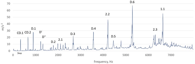
In the frequency domain, the above modulation produces minor deterministic components in the vicinity of the meshing frequency and at multiples of rotation frequencies of the gearwheel and pinion. The DPs of helical and bevel gears use the above dominant components together with minor ones for estimating a gear state.
For epicyclical gears, Vibropassport uses a more complex spatial-impulse model. This model takes into account the spatial movement of the planets and the sequence of meshing events of intermediate gears relative to a fixed sensor. In the frequency domain, such interactions are displayed not as single, but as grouped dominant components, which are concentrated around the meshing frequency and its multiples. The results of above model validation using a wind turbine planetary gearbox were published recently [28] confirming its applicability. The main gearbox of the tested helicopter has two epicyclical stages: the differential (D) and the closing link of differential (CD). In the spectrum shown in Fig. 5, the dominant components D.1…D.6 reflect the energy of dynamic interactions of the D-stage gears, while CD.1, CD.2 represent the energy of the CD-stage gears. The model adapted to the gearbox also reflects the influence of the double crown gear connecting D and CD stages. Unevenness of this gear appears in the spectrum as the component D' whereas the influence of the rotating main rotor trajectory is reflected by component D''.
To validate the DPs adapted for this helicopter, the helicopter test trials were provided. The prototype of the autonomous measurement system, which was used for this purpose, is presented further in Subsection 2.2, and the test methodology is considered in Subsection 2.3.
2.2. Measurement system
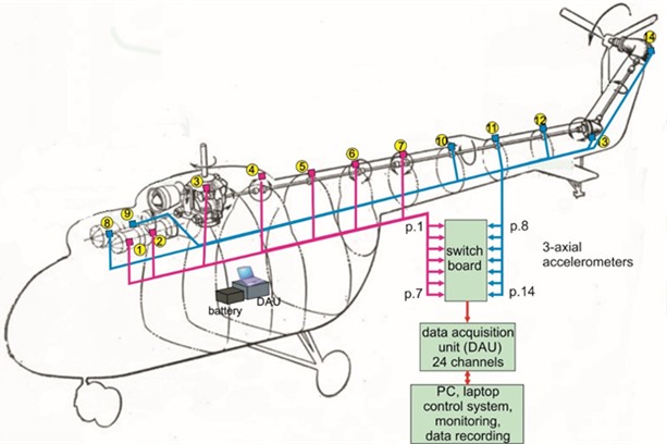
The prototype of autonomous vibration diagnostic system for a single inspection of helicopters includes sensor and measured parts, which layout is presented in Fig. 6.
Fig. 6Layout of sensors and measured parts on a helicopter
2.2.1. Sensing part
The core of the measurement system consists of sensors that provide information on the vibration state of engines, gearboxes and drive train. Brief characteristics of the sensors used in the system, its mounting type and location in the helicopter are presented in Table 2.
Table 2Standardized DPs of helicopter power units
Rotating unit | Mounting point | Sensor kind | Frequency range, Hz | Highest , t °C | Mounting type |
Front engine Rear engine | Front mount Rigging bracket | АР22 HBK 4527 | 2-20000 0.3-10000 | 120 180 | Bracket with screw |
Main gearbox | Cover | АР22 | 2-20000 | 120 | Screw stud |
Drive train supports | Support | АР22 | 2-20000 | 120 | Metal washer and cyanoacrylate glue |
Angular gearbox | Cast body | АР22 | 2-20000 | 120 | |
Tail rotor gearbox | Cast body | АР22 | 2-20000 | 120 |
In order to provide the sensitivity assumed by the models of Vibropassport, the system must provide the maximum information content of the measured vibration. The latter is ensured by the enhanced capabilities of vibration sensors in three aspects: spatial, frequency and amplitude.
In the spatial aspect, the maximum information is extracted through the use of 3-axial accelerometers which measure the spatial vector of vibration (Fig. 7(a)). Fig. 7(b) shows two types of three-axial accelerometers with a bracket-mounted stud. The example of bracket-mounted sensor is illustrated in Fig. 8(a). The bracket, fitted to the rigging unit, ensures the orientation of the accelerometer measurement axes in accordance with the engine axes.
Fig. 73-axial vibration and sensors. Photo: A. Safonovs, 12.09.2025, Riga
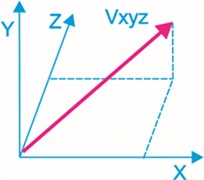
a) Spatial vector of vibration
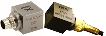
b) Types of applied accelerometers
Fig. 8Orientation of axis and different responses. Photo: A. Safonovs, 20.09.2025, Tbilisi
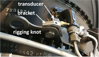
a) Bracket mounted sensor
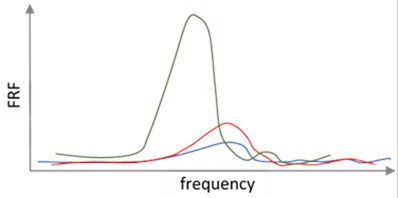
b) Diagram of 3-axial responses
Vibration signal depends on the measurement direction due to differences in the vibration transmission paths. Fig. 8(b) illustrates how the design of the rigging unit and bracket (Fig. 8(a)) implements a dominant frequency response function (FRF) in the axial direction (green) that exceeds responses in the radial (blue) and tangential (red) directions. The spatial vector measurement expands the diagnostic capabilities. Firstly, the spatial vector better reflects the energy ratio of the broadband vibration components, which are used for diagnosing the engine units and gearboxes. FRF difference in Fig. 8b may illustrate a potential error when measurements are taken only in the radial (blue) or axial (green) directions. Another benefit of spatial vector is its ability to self-align with the unit axis of rotation. The example of engine-mounted transducer (Fig. 8(a)) illustrates the method of sensor axes orientation in parallel to the rotation axis, radially and tangentially. Such an orientation, for instance, ensures an assessment of aero unbalance of the engine rotor or the condition of the engine fastening units.
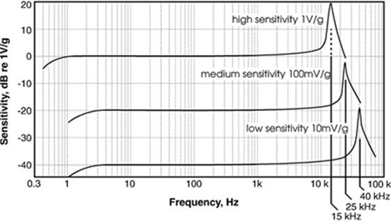
A wide frequency range of vibration measurement is required to allow resolution assumed by Vibropassport models. For example, the blade wakes affecting the guide vanes of an engine excite vibration in the frequency band of 30-40 kHz and over. To obtain information about such an interaction, it is necessary to measure vibration signals in an extended frequency range, and this turns out to be a problem. Depending on the type of sensor, the resonant frequency specified by the manufacturer varies widely [29], as illustrated in Fig. 9. For vibration measurements, only the part with a linear FRF is available that is limited (< 10 kHz), and when a transducer is fixed at a massive housing, its resonant moves even to a lower frequency. Therefore, the linear range available for vibration measurements typically does not exceed several kilohertz, while Vibropassport DPs require more than 20 kHz. The reference principle of DPs calculation allows extending the frequency range up to trans-resonant zones of the sensor comparing neighboring components with lightly different FRFs. The amplitude range of vibration in the system depends on the dynamic range of the measurement channel and so-called “noise” of a sensor. The dynamic range due to 24-bit bit rate of analog-to-digital converter exceeds 138 dB, but the actually used range is about 120…130 dB due sensor noise, caused by electrical circuit of the sensor. As the peak amplitudes of the measured signals vary between helicopter units, the automatic gain controller in the measurement channel allows “tuning” by shifting the above mentioned dynamic range.
Uncertainty of data acquisition depends on vibration amplitudes and frequency range. Minimal uncertainty is 1.5 % for vibration components with amplitudes of 10-1000 m/s2 in frequency range up to 10 kHz. Amplitude uncertainty increases with decreasing amplitude and growing frequency of vibration components. Errors in frequency determination is an order less, as depends mainly on sampling frequency and less on a random nature of vibration amplitudes.
Fig. 9Frequency resonant and sensitivity of piezoelectric sensors
2.2.2. Measurement part
A schematic diagram of the manufactured system prototype for the practical implementation of Vibropassport in an operating helicopter is illustrated in Fig. 6. The system includes three-axial piezo-electric accelerometers for measuring vibration (Table 2), brackets for transducers mounting in a specific location, connecting cables, switchboard, 24-channel data acquisition unit (DAU) and laptop. Accelerometers transform vibration of the rotating unit into an electrical signal, which is transmitted through the cables to the DAU. Each cable is fastened with adhesive pads to prevent it from being blown off by airflow or other incidents. The length of each cable is adapted to ensure that the transducers are properly connected. The switchboard provides a sequential connection of two transducer groups to the input of DAU. These group combinations are illustrated by magenta and blue colors in Fig. 6. The first group combines the signals from transducers of zones 1-7 including the left engine, and the second one combines transducers 8-14 with a correct engine. In addition to vibration signals, the switchboard transmits three rotation signals from the one engine unit to the main gearbox. The DAU processes and measures the signals of vibration and rotation, converting them into the digital form (sampling frequency of 65,536 kHz) and transmitting it to the laptop. The software installed in the laptop measures vibration and rotation signals and recording. A 512 Ah portable power station is included in the system to reduce interference and provide autonomous and stable power for the DAU, laptop and switchboard.
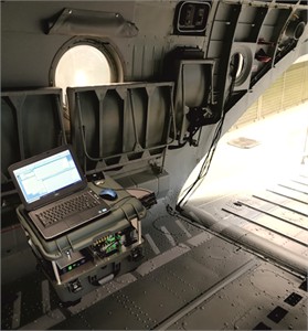
To meet field usage requirements, the system must be compact and transportable. The equipment must have low weight and dimensions to simplify its air, train or car transportation into a helicopter. Transportation of equipment as a baggage requires the use of ruggedized cases to protect it from damage. The cases must be dust- and moisture-proof, taking into account the various external conditions at the place of possible destination. The equipment units in the cases must be securely fastened to prevent damage during transportation. Taken into account these requirements, the system components were housed into two ruggedized cases equipped with wheels and retractable handles for easy transportation. Case 1 contains a set of measurement equipment that can be converted into a measurement station for the system operator. The measurement station installed in the helicopter cargo cabin is shown in Fig. 10.
The station contains a panel with 48 connectors for sensor extension cables, switchboard, channel group selector, 24-channel DAU, control laptop and battery power supply. Case 2 contains all accelerometers with mounting brackets cables and the instruments with accessories to be installed in a helicopter. The mass of the case with measurement station is 23 kg, and case 2 with sensors and accessories weighs 17 kg both within the standard luggage limitations of commercial airlines.
Fig. 10Measurement station in operating condition. Photo: A. Safonovs, 20.09.2025, Tbilisi
2.3. Methodological issues of vibropassport application
The design of each helicopter rotating unit and its operating mode influence vibration, therefore further adaptation of Vibropassport to the type of helicopter is required. The influence of design factors is taken into account when determining the location and method of sensor installation at the unit. The possible influence of operating and ambient factors is taken into account preparing the signal recording methods and testing procedures.
2.3.1. Sensor installation place and methods
Two groups of factors determine the choice of location and method for installing vibration sensors in the helicopter for an operating test. The first group includes safety requirements for using an autonomous measurement system on a serial helicopter. The system elements must not violate the integrity and configuration of helicopter units and create risks for its operability. For example, the sensor together with the bracket and cable should not interfere with the controls and regulators of the helicopter units. This group also includes cost-saving requirements for minimizing the time and labor costs of installing and dismantling the sensors as an autonomous system. This means also that fastening of sensors and cables should not require a lot of operations, for example, dismantling any helicopter elements or units, or the use of complex equipment, such as lifts.
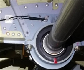
Another group takes into account the technical requirements for vibration measurement. When a location for installing a sensor is chosen, it is necessary to consider the fact that external vibration sources reduce the information content of components used by DPs. The sensor location is selected taking into account the minimization of both external influences and the attenuation of informative components of vibration, for which it is desirable to shorten the path from the vibration source to the sensor. The method of sensor fixture (Fig. 11) also affects the range of the measured vibration [30].
When the sensor is attached with a stud, it ensures the lower signal attenuation and the larger width of frequency range that is important for the unit with multiple sources. At the same time, for units with dominating vibration components, like bearings of drive train or angular and tail gearboxes, the requirements to the sensor fixture are softer. The choice of the optimal location and sensors installation method comes down to a compromise between reducing the influence of external sources and minimizing the signal attenuation, while unconditionally meeting the safety requirements. Fixed at the engine and gearbox, the sensor measures vibration from several diagnosed units, so the optimal location shall have the highest priority. This priority is formulated based on the preliminary analysis and identification of the vibration components measured during the Vibropassport adaptation. For example, for the main gearbox, the location on the gearbox cover (Fig. 12(a)) was chosen as the optimal location, in which the vibration components caused by the most loaded gears (shown in spectrum on Fig. 5) have the largest amplitudes.
Fig. 11Attachment technique influence on FRF
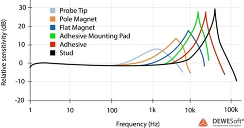
Fig. 12Transducers of power station. Photo: A. Safonovs, 20.09.2025, Tbilisi
a) Main gearbox
b) Engine
The system has five measurement points for diagnosing both engines and the main gearbox: on the housings of power turbine (Fig. 8(a)) and compressor (Fig. 12(b)) and on the cover of gearbox (Fig. 12(a)). The sensors on the engines and main gearbox are attached using threaded studs providing better transfer of dynamic excitations from multiple vibration sources.
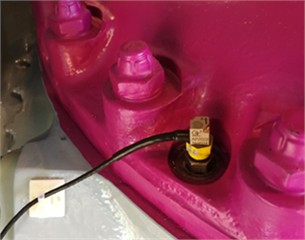
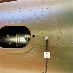
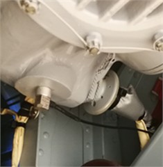
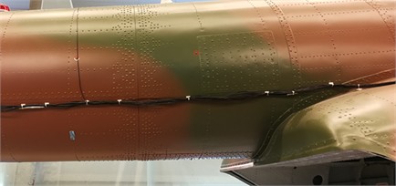
Unlike the engines and main gearbox, a different attachment method is used for the units of drive train. An aluminum-alloy washer, which is glued directly to the body with cyanoacrylate glue, is attached to the sensor using a threaded stud. Because the washer has a small surface area (less than 1 cm2), the sensor can be installed at nearly any surface with slight curvature. For the system prototype, the sensor locations for drive train bearings are chosen depending on the support position. On supports 1-3, which are accessible from the cargo cabin, sensors are installed at the support bodies riveted to the fuselage power frame (Fig. 13(a)). Supports 4-7 inside the tail boom are not accessible, so the sensors are installed outside at the attachment zones of the support elements (Fig. 13(b)).
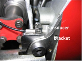
On the tail (Fig. 14(a)) and angular (Fig. 14(b)) gearboxes, the sensors were installed at a cast housing that finely transmits excitations from the gear bearings.
Fig. 13Transducers of drive train. Photo: A. Safonovs, 20.09.2025, Tbilisi
a) 2nd support
b) 5th support
Fig. 14Transducers of drive train gearboxes. Photo: A. Safonovs, 20.09.2025, Tbilisi
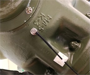
a) Tail
b) Angular
The connecting cables of the drive train sensors are secured with flexible ties using a glued plastic fastener (white squares in Fig. 14). The cables were then connected into the harness, which was secured to the fuselage elements along its entire length with the same ties (Fig. 15) towards the measurement station in the cargo compartment.
Fig. 15Transmission sensors cable harness (A. Safonovs, 20.09.2025, Tbilisi)
2.3.2. Trial testing and recording methodology
The testing and recording methodology defines the operating modes of the helicopter power plant and the signal recording procedure aiming to ensure the similarity of tests regardless of various ambient conditions. For the selected type helicopter, the procedure provides for ground testing with the alternate use of two engines. To reduce random influence on a diagnosis, Vibropassport uses two “adjacent” operating modes – the maximum permissible and the reduced one, which rotation speed is 1±0.3 % less than the maximum one. Totally, the test procedure includes the signal recording during the alternate operation of two engines in two stationary operating modes of each one. To provide the stationary operation mode of engines, the pilot controls the rotation speed of gas generator within ±0.2 % of the mean value. During the test, one of helicopter engines (charged) running at a higher speed, while the second remains idle. Atmospheric factors (pressure, humidity and temperature) and the actions of pilot operating the helicopter may influence the test conditions. The test routines, which are adapted to the helicopter type, must ensure test consistency through repeatability of the helicopter testing mode. To provide this repeatability, the procedure involves testing the helicopter with a fixed load, minimum fuel rest and a fixed number of personnel on board. With the same takeoff weight of the tested helicopter, the main rotor thrust for takeoff and required engine power remain unchanged for each test. The pilot determines the maximum permissible mode for test repeatability, as external conditions (temperature, pressure) vary. He simultaneously increases the power of the running engine and the main rotor pitch until at least one of the chassis wheels loses contact with the ground.
The data registration technique defines the key parameters – the sampling frequency and duration of signal recording. The technique sets the sampling frequency taking into account the frequency ranges determined by the models of rotating units. For engines of selected helicopter type, the upper limit of the frequency range is defined by the models of the gas generator stages and the gearbox. The upper frequency limit of the specified models was fixed as 25 kHz, therefore, to avoid aliasing, the sampling frequency was arranged 65,536 Hz. The duration of signal records was determined by requirements of the DP calculation algorithms for the minimum averaging number and, taking into account the sampling frequency, was 60 s.
The testing procedures includes the installation and dismantling of system equipment and two stages of testing - preparation and registration. Installation and dismantling on the helicopter are carried out according to predetermined routines and takes about 3.5 hours. After completion of installation, the testing begins, when the operator of diagnostic system coordinates actions with the pilot using an intercom.
The first stage of testing involves starting and warming up both engines, as provided for in the helicopter operating manual. As a part of trial application of the system, the system operator during warming up validates all the vibration and rotation signals. After warming up, the pilot sets the first engine to the maximum permissible operating mode and holds it in the specified range, informing the system operator about the readiness to start recording.
At the registration stage, under the operator supervision, the system records the signals of the first group of sensors (Fig. 6) at the maximum mode for 60 seconds and saves the recorded data file. Then the operator informs the pilot about first mode completion, and after reducing power of the testing mode, and the recording of the vibration and rotation signals of the first sensor group is repeated. After recording of first group signals on both modes, the test and recording routines are repeated for the second signal group. The result of the helicopter test contains four data files with a volume of 230 MB each. The total duration of engine operation during the test (including warming up) does not exceed 10-12 minutes.
2.4. Vibropassport efficiency
Since the practical implementation of Vibropassport has only recently begun, statistical data are not yet available. Therefore, the diagnostic accuracy is currently estimated based on experimental results and trial applications. Sensitivity to the typical damage scale is estimated using the seeded faults, while the probability of correct diagnosis is determined from the results of test series.
The accuracy rate of a specific DP depends on the purpose of use (monitoring or one-time diagnosis) and complexity of the diagnosed unit. For the units with a dominant vibration source, like a drive train bearing installed in a separate housing, the sensitivity to defects is higher, and a correct diagnosis increases accordingly. For example, the adaptive technique is capable of detecting damage in a bearing race with a depth of at least 0.1 mm [17]. For wind turbines, where the method is used for bearing condition monitoring, the probability of in-time damage detection approaches 100 %. Conversely, when diagnosing a bearing in a running jet engine without accumulated statistical data, the sensitivity decreases and the minimum size of the detected defect is expected to be larger (at least 0.15-0.2 mm). For a jet engines, experimental evaluations of Vibropassport sensitivity to a non-critical damage that worsens the unit functionality, but does not lead to immediate failure have been conducted. One such example is a simulated compressor blade defect representing a torn blade tip [13]. The corresponding DP characterizes such damages as a percentage ratio between the number of damaged blades and the total number of blades in the stage, indicating the scale of the degradation. The sensitivity of this DP was experimentally estimated at 15 % that means, for example, the stage could be identified as damaged if at least 15 % of its blades demonstrate damage of the above scale. For a helicopter engine drive gearbox, non-critical damage was considered as wear of the teeth contact surface with a depth up to 0.3 mm [15]. The Experimental results with seeded faults of the above scale demonstrated the DP sensitivity of approximately 15 % of the teeth in a gearwheel or pinion. Meanwhile, the critical defects, like a lost blade or a broken tooth were detected by Vibropassport in all experimental cases with a running engine.
The degree of the Vibropassport applicability depends on the specific unit design. The Vibropassport uses the diagnostic methods that are universal for typical rotating units, but the data processing algorithms require adaptation for each unit type. For example, the vibration model and the method for compressor stages diagnosing are universal for all axial compressors but the algorithm of DP calculation depends on blade number in the stage. After adaptation to the type, the Vibropassport is applicable to any sample of this type.
3. Discussions
During the work, three tasks were solved: adaptation of Vibropassport DPs to the type of helicopter, system prototyping for specific helicopter type and its trial application with an operating helicopter.
Adaptation of Vibropassport included tuning the algorithms and 190 DPs listed in Table 1 to the technical and kinematic characteristics of the helicopter units. The tuning process covered not only the numbers of teeth, blades, and bearings and their geometry, but also the specific operating modes of the helicopter. For field testing, the operating modes were selected, in which one engine at idle, while the other provided the rotor power, keeping the helicopter on the ground.
The prototype of the measuring subsystem, briefly described in Section 2, was manufactured as transportable to enable field testing in any location. System prototype field testing included the post-transportation performance verification, validation of technical solutions, and the assessment of the compliance of recorded vibration and rotation signals. The technical solutions were validated during installation of the measurement system on the helicopter. The solution was reviewed jointly with the helicopter engineers and was considered acceptable if the installation of 14 sensors did not require the dismantling of any equipment, and if cable routing created no risks to the operability of the helicopter components. The same principle was applied to the operator workstation in the cockpit as shown in Fig. 10. The prototype performance in terms of data measurement and recording was assessed by two criteria. The correspondence between sizes and structure of the obtained data files in a time domain was the first criterion. Each file size corresponded to the sampling frequency and record duration. Moreover, vibration signal signatures of from each sensor were checked against known parameters of vibration and rotation signals. For instance, the check of rotation signals in time domain included visual inspection of the pulse shape and assessment of the duration of their period. The second criterion assessed the correspondence of frequency structure of vibration and rotation signals to vibration models and typical spectra. The spectra of vibration and rotation signals of similar engines, gearboxes, and bearings were used as the typical ones. As criteria for the vibration signatures check, the matching of component frequencies to the calculated values, and the amplitudes and their ratios corresponded to typical amplitude ranges. For example, the difference in the gearbox vibration amplitudes in the spectrum shown in Fig. 5 did not exceed typical value of 10-20 dB from similar components of another helicopter gearbox.
The applicability check of Vibropassport in terms of diagnostics was carried out using data from a single test of the helicopter. Before the test, the helicopter was overhauled, so all its units were considered serviceable. This means that the normalized DPs determined based on the test data must remain within the thresholds of the healthy condition. The primary validation criterion, was the compliance of unit DP with the common thresholds known for similar units. Since the distribution areas of the adapted DPs have not yet been determined, the standardized distribution areas were used for validation. Such areas expressed in the normalized scale had been previously established earlier for each type of DP within the framework of studies using specialized experimental setups mentioned earlier [13, 15, 17] and were subsequently validated on actual equipment [28]. Validation of the DPs calculated using the test data showed that most of them did not go beyond the common thresholds of healthy condition. Meanwhile, the DPs of some engine units approached the preset thresholds. Illustrative examples of DP validation are provided in the diagrams. The diagram in Fig. 16 compares the DPs of both engine gearboxes with the normalized scale indicator plotted on the left side in the diagram.
Fig. 16DP diagram of engine gears
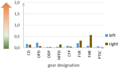
As noted in Section 2.1, the common distribution area of the Teeth DP for a serviceable gear lies between 0 and 0.5-0.6. Going beyond this area may indicate the appearance of a defect. Most gears exhibited DP values within the green zone of the scale (left) corresponding to the healthy gear state. However, the DP of FHR (horizontal flexible shaft) of the right engine approached the transition zone (from green to orange) indicating at a possible deviation from the normal condition. This anomaly may reflect irregularities in the operation of this rotating unit, although not necessarily be associated with a defect.
Fig. 17Non-stationarity DP of 1-5 compressor stages
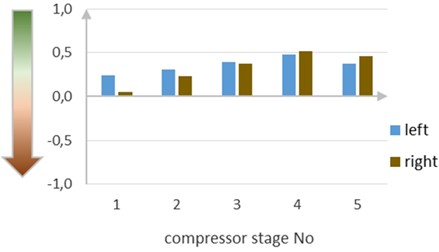
Another example of DP approaching to a healthy threshold is demonstrated in Fig. 17, and it illustrates the DP of flow non-stationarity in 1-5 compressor stages of both engines.
This DP has the negative normalized scale, and the fact that this parameter goes into negative zone may indicate deterioration in the stage performance. The diagram shows the DPs of 2nd to 5th stages of both compressors were within 0.2-0.5, corresponding to stable flow (healthy)condition. In contrast, the DP of the 1st stage of the left engine dropped to the threshold (< 0.05), indicating the presence of partial stall phenomena in the stage. The most probable reason may be, for example, a wind gust, aggravating the effect of airflow distortion at the engine intake by the main rotor wake.
Therefore, the trial operation of the system prototype with the adapted Vibropassport on the operating helicopter demonstrated its operability under field conditions and confirmed its capability for effective diagnostics during a single inspection.
4. Conclusions
Based on earlier validated Vibropassport algorithms the system for a single-inspection vibration diagnostics of a helicopter under field conditions was developed. To check practically the Vibropassport capabilities, its algorithms and diagnostic parameters were adapted to a middle-class helicopter type. The technical solutions implemented in the measuring subsystem meet the requirements of Vibropassport models and address the challenges of practical application in an operating helicopter. The compact and transportable prototype of the system is packed in two ruggedized, moisture- and dust-proof cases of 23 kg and 17 kg. Using the data measured in the prototype during a single inspection of the operating helicopter, the system calculated 190 diagnostic parameters for both engines, main gearbox and drive train units. Analysis of the calculated parameters showed that most values are within the common “healthy” thresholds established for similar units, which is consistent with the expected condition of the helicopter units after repair. As part of a trial test and – in the absence of statistics – this result indirectly confirms the applicability of the Vibropassport for diagnosing helicopter components based on single-inspection data.
The main result of this research is the confirmed operability of the system prototype and the demonstrated applicability of the Vibropassport techniques to an operating helicopter.
The next stage of this research involves trial application of the system prototype for other samples of the same helicopter type as well as on other types of helicopters.
References
-
W. E. Forsthoffer, “Preventive and predictive maintenance best practices,” in Forsthoffer’s Best Practice Handbook for Rotating Machinery, Elsevier, 2011, pp. 563–576, https://doi.org/10.1016/b978-0-08-096676-2.10011-6
-
“What is Predictive Maintenance?” TWI Global, https://www.twi-global.com/technical-knowledge/faqs/what-is-predictive-maintenance/
-
T. Lucht, V. Alieksieiev, T. Kämpfer, and P. Nyhuis, “Spare parts demand forecasting in maintenance, repair and overhaul,” in Proceedings of the Conference on Production Systems and Logistics, Jan. 2022, https://doi.org/10.15488/12179
-
I. Tumer and A. Bajwa, “A survey of aircraft engine health monitoring systems,” in 35th Joint Propulsion Conference and Exhibit, Jun. 1999, https://doi.org/10.2514/6.1999-2528
-
P. Knight, J. Cook, and H. Azzam, “Intelligent management of helicopter health and usage management systems data,” Proceedings of the Institution of Mechanical Engineers, Part G: Journal of Aerospace Engineering, Vol. 219, No. 6, pp. 507–524, Jun. 2005, https://doi.org/10.1243/095441005x33402
-
I. Stanton, K. Munir, A. Ikram, and M. El‐Bakry, “Predictive maintenance analytics and implementation for aircraft: Challenges and opportunities,” Systems Engineering, Vol. 26, No. 2, pp. 216–237, Dec. 2022, https://doi.org/10.1002/sys.21651
-
A. Mauricio, J. Qi, L. Zhou, W. Wang, D. Mba, and K. Gryllias, “Perspectives on health and usage monitoring systems (HUMS) of helicopters,” in MATEC Web of Conferences, Vol. 314, p. 02008, May 2020, https://doi.org/10.1051/matecconf/202031402008
-
“OnPoint Services.” GE Aviation, https://www.geaviation.com/services/regional-business/onpoint/
-
“Engine health and condition monitoring.” Meggitt Sensing Systems. https://meggittsensing.com/aerospace/product/engine-health-and-condition-monitoring/
-
“Observe, decide, guide intelligence onboard.” Safran Electronics and Defense, https://www.safran-electronics-defense.com/aerospace/military-aircraft/propulsion-system-solutions/health-monitoring-military-aircraft
-
L. Wang, Y. Yin, A. Wang, X. Heng, and M. Jin, “Dynamic modeling and vibration characteristics for a high-speed aero-engine rotor with blade off,” Applied Sciences, Vol. 11, No. 20, p. 9674, Oct. 2021, https://doi.org/10.3390/app11209674
-
L. M. Gelman, D. A. Kripak, V. V. Fedorov, and L. N. Udovenko, “Condition monitoring diagnosis methods of helicopter units,” Mechanical Systems and Signal Processing, Vol. 14, No. 4, pp. 613–624, Jul. 2000, https://doi.org/10.1006/mssp.2000.1295
-
A. Mironov and P. Doronkin, “Verification of vibration diagnostic technique for flow path of turbomachines,” in Reliability and Statistics in Transportation and Communication, pp. 221–230, Feb. 2024, https://doi.org/10.1007/978-3-031-53598-7_20
-
X. Sun, T. Wang, R. Zhang, F. Gu, and A. D. Ball, “Numerical modelling of vibration responses of helical gears under progressive tooth wear for condition monitoring,” Mathematics, Vol. 9, No. 3, p. 213, Jan. 2021, https://doi.org/10.3390/math9030213
-
A. Mironov and P. Doronkin, “Quantitative evaluation of teeth gears applying techniques of Vibropassport,” in 22nd International Scientific Conference, Engineering for Rural Development, 2023.
-
S. Fábry and M. Češkovič, “Aircraft gas turbine engine vibration diagnostics,” MAD – Magazine of Aviation Development, Vol. 5, No. 4, p. 24, Nov. 2017, https://doi.org/10.14311/mad.2017.04.04
-
A. Mironov, P. Doronkin, and A. Priklonsky, “Advanced vibration technique for monitoring of helicopter bearings,” in 40th European Rotorcraft Forum 2014, pp. 149–158, Sep. 2014.
-
D. A. Dousis, “Development and integration of onboard drive train vibration monitoring systems,” in VFS Forum 50, May 1994.
-
“Onboard Vibration Monitoring System/HUMS.” Honeywell Aerospace, Feb. 2018, https://aerospace.honeywell.com/content/dam/aerobt/en/documents/learn/services/maintenance-and-service-plans/brochures/n61-1549-000-000-onboardvibrationmonitoringsystemhums_bro.pdf
-
“Vibration health or alternative monitoring technologies for helicopters.” Report EASA_REP_RESEA_2012_6, 2014, https://aerossurance.com/helicopters/easa-hums-activity
-
“Bell412/412EP, Maintenance Manual, Volume 1 General Information, Revision 32.” Bell, Mar. 2022, https://www.bellcustomer.com.
-
R. Przysowa, B. Gawron, A. Kułaszka, and K. Placha-Hetman, “Polish experience from the operation of helicopters under harsh conditions,” Journal of KONBiN, Vol. 48, No. 1, pp. 263–299, Dec. 2018, https://doi.org/10.2478/jok-2018-0056
-
S. Lahdelma, E. Juuso, and J. Immonen, “Advanced condition monitoring of epicyclic gearboxes,” in 10th International Conference on Condition Monitoring and Machinery Failure Prevention Technologies (CM 2013 / MFPT), Vol. 1, Jun. 2013.
-
L. Zhuang, “Experimental analyses of vibration and noise of faulted planetary gearbox,” in Proceeding of Inter-noise 2014, 2014.
-
W. Bartelmus and R. Zimroz, “Vibration diagnostic method for planetary gearboxes under varying external load with regard to cyclostationary analysis,” Wrocław, Drukarnia Oficyny Wydawniczej Politechniki Wrocławskiej, 2009.
-
A. Mironov and D. Mironovs, “Vibration diagnostics of planetary gearbox of engineering and transport machines based on spatial model application,” in 17th International Scientific Conference Engineering for Rural Development, pp. 1315–1321, May 2018, https://doi.org/10.22616/erdev2018.17.n108
-
A. Mironov, P. Doronkin, and D. Mironovs, “Research and practical application of vibration transfer functions in diagnostics of jet engine,” Lecture Notes in Networks and Systems, pp. 431–439, Mar. 2019, https://doi.org/10.1007/978-3-030-12450-2_40
-
A. Mironov, P. Doronkin, and V. Kuzmickis, “Trial application of vibropassport diagnostic techniques to gearbox of wind turbine,” in 24th International Scientific Conference Engineering for Rural Development, Vol. 24, May 2025, https://doi.org/10.22616/erdev.2025.24.tf086
-
“Choosing an accelerometer.” Wilcoxon, https://wilcoxon.com/blog/choosing-an-accelerometer
-
“Vibration Measurement and Analysis.” DeweSoft, Dec. 2025, https://training.dewesoft.com/online/course/vibration-measurement
About this article

The administrative and technical support of this research is provided by the Center of Competence in Energy and Transport (SIA “ETKC”). This research was funded by the Central Finance and Contracting Agency of the Republic of Latvia, project number 5.1.1.2.i.0/2/24/A/CFLA/002 “Application of predictive vibration technologies for cost and time saving of helicopter maintenance”.
The datasets generated during and/or analyzed during the current study are available from the corresponding author on reasonable request.
Aleksey Mironov: conceptualization, methodology, validation, formal analysis, writing-original draft preparation, data curation; writing-review and editing, project administration, funding acquisition. Andris Chate: conceptualization. Pavel Doronkin: methodology, software, validation, writing-original draft preparation, data curation; writing-review and editing, visualization. Aleksejs Safonovs: validation, visualization
The authors declare that they have no conflict of interest.
