Abstract
In this paper, a novel control approach, namely fuzzy dynamic self-tuning-based linear active disturbance rejection control (FDS-LADRC), is proposed for the speed loop system of permanent magnet synchronous motors (PMSMs). Specifically, a control framework based on the linear active disturbance rejection control (LADRC) is presented. Fuzzy dynamic self-regulators are developed to enable simultaneous adaptive adjustments of both the controller and observer parameters. Additionally, the stability analysis is provided. A series of numerical simulations demonstrates that FDS-LADRC achieves superior adaptivity, transient performance, disturbance rejection capability, and anti-noise ability under various operating conditions. For instance, during no-load startup, compared with the traditional LADRC, nonlinear active disturbance rejection control (ADRC), a variant of FDS-LADRC named IT2FDS which utilizes interval type-2 fuzzy systems as fuzzy dynamic self-regulators, a state-of-the-art fractional-order ADRC with fuzzy self-tuning (FSFOADRC), and sliding mode control (SMC), FDS-LADRC reduces overshoot by 10.82 %, 13.55 %, 7.36 %, 5.53 %, and 3.94 %, respectively, and shortens settling time by 0.0132 s, 0.0076 s, 0.0139 s, 0.0009 s, and 0.0156 s, respectively. Finally, corresponding real-world experiments are conducted to validate the effectiveness and superiority of FDS-LADRC.
1. Introduction
PMSMs, characterized by high power density, superior energy conversion efficiency, and excellent dynamic response performance, have emerged as core drive units in high-end equipment fields, including the new energy electric vehicle industry, aerospace servo systems, marine propulsion systems, and so on [1]-[8]. Field-oriented control (FOC) is the primary control architecture for PMSMs, in which the speed loop directly determines the system’s robustness and disturbance rejection capability [9]. In practical engineering, proportional-integral (PI) controllers [10] are widely used in the speed loop for their simplicity but still face critical challenges: (a) Nonlinear coupling and parameter sensitivity: The PMSM model is strongly nonlinear and coupled, with parameters (e.g., resistance, inductance) drifting with temperature, magnetic saturation, and aging. PI controllers struggle to cope with these unfavorable factors. (b) Robustness bottleneck under compound disturbances: The speed loop must suppress external load torque changes, internal parameter perturbations, and inverter-induced harmonics, but fixed-gain PI controllers lack online adaptability, failing to handle wide-frequency disturbances. (c) Trade-off between dynamic response and steady-state accuracy: The speed loop needs to balance fast command tracking and overshoot suppression. Although PI controllers can adjust the system bandwidth through PI parameter tuning, their linear control structure leads to inevitable performance trade-offs – improvements in dynamic response often come at the cost of reduced steady-state accuracy or weakened disturbance rejection capability. (d) Control complexity in multi-objective optimization: Advanced drive systems demand coordinated optimization of disturbance rejection, parameter robustness, and dynamic response. PI controllers rely on empirical tuning, making it difficult to balance these competing objectives (e.g., higher proportional gain improves response but increases noise sensitivity). Therefore, based on the above analysis, there is an urgent requirement to explore new intelligent control strategies to address these challenges. This also constitutes one of the main motivations of this study.
Recently, a plethora of advanced control algorithms have been proposed, including SMC and its variants [11]-[13], fuzzy-related control methods [14]-[19] and neural network control methods [20]-[21]. Despite their promising performance in various engineering applications, these approaches still have some limitations including the chattering phenomenon of SMC, the curse of dimensionality for fuzzy-related control methods, and the high demand for computational resources for neural network control methods. In addition, these approaches are not very effective when facing external disturbances. Against this backdrop, ADRC, utilizing an extended state observer (ESO) to estimate and dynamically compensate for the “total disturbance” of both internal and external system perturbations in real time [22], demonstrates strong anti-disturbance capabilities. It offers several unique advantages: (a) Model independence and strong anti-disturbance capability: It does not require an accurate mathematical model. By introducing the concept of “total disturbance” and compensating for it, ADRC achieves strong disturbance rejection capabilities. (b) Avoidance of empirical and data dependence: It does not rely on empirical rules or large-scale training datasets. (c) Intuitive and feasible control structure: It combines physical intuitiveness with engineering feasibility. However, in addition to an ESO, the classical ADRC architecture incorporates a tracking differentiator (TD) and nonlinear state error feedback (NSEF), leading to high complexity in parameter tuning. To address this issue, Gao [23] proposed LADRC, which reconstructs the control architecture by adopting a linear ESO (LESO) and linear state error feedback (LSEF). While retaining the disturbance estimation and compensation mechanism, LADRC reduces the tunable parameters to two physically meaningful variables: the observer bandwidth and the controller bandwidth [24], significantly simplifying the complexity of engineering implementation. These improvements have significantly promoted the application of ADRC theory in various control scenarios, such as exoskeleton medical robots [25]-[26], delta wing aircraft [27], and remotely operated vehicle [28].
Particularly, for PMSMs, Yan et al. [29] developed an enhanced two-degree-of-freedom integrated position tracking control method based on an improved LADRC with the sliding mode compensation function, which genuinely implemented the complete decoupling of dynamic performance and disturbance rejection performance. Liu et al. [30] proposed a predictive functional control method based on a LESO. By utilizing the LESO to observe and estimate the system’s total disturbance, this method improved the anti-disturbance capability of the PMSM to a certain extent. Shen et al. [31] presented a simulation study of LADRC applied to PMSM systems, demonstrating that LADRC provided effective control over load disturbances, viscous damping, and other uncertainties. Cui et al. [32] conducted a comprehensive review of LADRC-based multi-source disturbance suppression methods. Yang et al. [33] proposed an innovative control strategy targeting harmonic disturbances in the PMSM current loop. This strategy introduced a novel LADRC controller based on a complex-coefficient LESO, and experimental results validated its effectiveness. Tian et al. [34] designed an adaptive LADRC for the current loop of the PMSM to suppress uncertain periodic and aperiodic disturbances that cause current ripples. Cui et al. [35] proposed a new LADRC control method incorporating lead compensation and a cascaded LESO for the PMSM speed loop. This method enhanced the original total disturbance estimation mechanism by adding a lead compensation link, significantly improving the PMSM’s load disturbance rejection capability. The effectiveness and superiority of this approach were demonstrated through simulation studies involving sudden load application and removal at the rated speed of the PMSM. Zhao et al. [36] proposed a new control strategy for the PMSM system, where the speed loop utilized a second-order modified ADRC, and the current loop employed a first-order LADRC. Additionally, an LTD module was integrated to filter the output speed, significantly boosting the robustness of the PMSM system. Qu et al. [37] introduced a sensorless FOC control method for PMSM drives based on an enhanced LADRC. By promptly estimating and compensating for internal disturbances such as parameter variations and changes in current regulation quality in the current control loop, this approach improved the rotor position estimation performance of the PMSM system. Through leveraging fuzzy logic to adaptively adjust the bandwidth of LESO, Sancio et al. [38] introduced a fuzzy-based adaptive LADRC control strategy specifically tailored for the high-speed PMSM system, which achieved a faster transient response to external disturbances and model uncertainties. Li et al. [39] developed a novel gain-adaptive LESO based on the gain-adaptive regulation law. This new gain-adaptive LESO exhibited excellent noise suppression capabilities. Through the aforementioned review and investigation, it can be observed that in most existing studies including [29]-[33], [35]-[37], both the parameters of the controller and the bandwidth of the observer in LADRC are typically fixed, which makes the system lack flexibility and adaptability. In addition, several existing adaptive LADRC methods, e.g., [34] and [39], focus solely on adjusting the bandwidth of the LESO while overlooking the optimization of controller parameters. This limitation leads to a severe mismatch between the disturbance estimation performance of the observer and the control regulation capability of the controller, ultimately restricting the overall performance of the PMSM control system. Besides, most of the methods still require a cumbersome parameter tuning process to achieve optimal performance.
Inspired and motivated by these limitations, an enhanced LADRC control approach leveraging the fuzzy logic technique, namely FDS-LADRC, is proposed for the PMSM speed loop system. To be specific, an LADRC control framework for the PMSM speed loop system is established. Subsequently, fuzzy dynamic self-regulators are designed using the system error and its derivative to adaptively adjust the controller parameters and the observer bandwidth. This leads to the development of an adaptive fuzzy controller and an adaptive fuzzy LESO, enhancing the system’s adaptability, transient performance, disturbance rejection capability, and anti-noise ability. Furthermore, the corresponding stability analysis is discussed. Finally, the effectiveness and superiority of the proposed FDS-LADRC method are demonstrated through a series of numerical simulations and real-world experiments. Note that compared with some existing fuzzy-based control methods including hybrid fuzzy LADRC [38] and fractional-order fuzzy LADRC [19], the proposed FDS-LADRC simultaneously tunes the controller parameters and the bandwidth of the observer, breaking the performance bottlenecks of one-sided parameter adjustment and achieving more comprehensive improvements in the transient response, anti-disturbance ability, and engineering adaptability. The main contributions of this paper can be summarized as follows:
(a) An enhanced LADRC control method leveraging the fuzzy dynamic self-tuning mechanism, i.e., FDS-LADRC, is proposed for the PMSM speed loop system, and the corresponding stability analysis is presented.
(b) In FDS-LADRC, an adaptive fuzzy controller and an adaptive fuzzy LESO are simultaneously developed, which flexibly adjust both the controller parameters and the observer bandwidth in real time, effectively enhancing the adaptability, transient performance, disturbance rejection capability, and anti-noise ability of the PMSM speed loop system.
(c) A number of comparative numerical simulations are conducted. The results demonstrate that the proposed FDS-LADRC method possesses certain superiority in many aspects compared with some baseline and state-of-the-art control methods. In addition, to verify the feasibility and effectiveness of FDS-LADRC, a series of real-world experiments are also carried out.
The remainder of this paper is organized as follows. Section 2 introduces the mathematical model of the PMSM speed loop. Section 3 presents the proposed FDS-LADRC method in detail. The stability analysis of FDS-LADRC is discussed in Section 4. A series of numerical simulations and real-world experiments in various cases are reported in Section 5 and Section 6, respectively. Finally, the conclusion and future work are drawn in Section 7.
2. The mathematical model of the PMSM speed loop
Assuming that the PMSM is in an ideal or balanced state, the following conditions are satisfied: (a) Magnetic saturation of the motor core is neglected. (b) Eddy current losses and hysteresis losses in the motor rotor are ignored. (c) The currents and flux linkages (flux) in the motor exhibit symmetrical three-phase sinusoidal waves. (d) The internal parameters of the motor remain constant. Under these assumptions, the mathematical model of the PMSM stator voltage in the - synchronous rotating coordinate is given by [40]:
where and are the -axis and -axis components of the stator voltage, respectively; and are the -axis and -axis components of the stator current, respectively; is the electrical angular velocity of the rotor; is the stator resistance; and are the -axis and -axis components of the stator flux linkage, respectively.
The relationship between the stator flux linkage and inductance is given by [40]:
where and represent the d-axis and q-axis components of the stator inductance in the - synchronous rotating coordinate, respectively, and denotes the nominal value of the rotor flux linkage.
In addition, the mechanical motion model of the PMSM is [40]:
where represents the mechanical angular velocity of the rotor, which is related to the electrical angular velocity by the equation , where is the number of pole pairs in the stator winding. denotes the moment of inertia, is the electromagnetic torque, is the load torque, and is the viscous friction damping coefficient.
However, in the actual operation, the internal mechanical and electromagnetic parameters of PMSM cannot remain constant. These parameters may vary due to magnetic saturation and temperature fluctuations. Therefore, under such conditions, the electromagnetic torque formula of PMSM needs to be redefined to account for these variations [40]:
where represents the effective flux linkage, and denotes the perturbation in electromagnetic torque resulting from parameter variations.
Furthermore, when the PMSM is subjected to external load disturbances and variations in the moment of inertia and viscous friction damping coefficient, the mechanical motion model of the PMSM is described as [40]:
where represents the perturbation in the mechanical motion model caused by parameter variations.
By combining Eq. (4) and Eq. (5), the mathematical model of the PMSM speed loop under the influence of internal parameter variations and external load disturbances can be derived as [40]:
3. Detailed design procedures of FDS-LADRC
3.1. The overall control structure of FDS-LADRC for the PMSM speed loop
From Eq. (6), it can be seen that the mathematical model of the PMSM speed loop can be expressed in the form of a first-order differential equation. Typically, the order of the LADRC corresponds to the order of the controlled object. Therefore, for the PMSM speed loop, a first-order LADRC can be effectively employed for control. The first-order LADRC mainly consists of three linear components: the first-order linear tracking differentiator (FOLTD), the second-order linear extended state observer (SOLESO), and the LSEF. By rewriting Eq. (6) in a general form, we have:
where represents the sum of internal parameter perturbations and external load disturbances in the PMSM speed loop. This term is referred to as the “total disturbance” within the LADRC framework and is estimated and compensated by the SOLESO. Additionally, denotes the current gain coefficient, and represents the controller output control quantity, which is the q-axis current.
By defining the state variables for Eq. (7) as , , and , Eq. (7) can be rewritten in the form of a state-space equation:
Designing a SOLESO for the controlled object represented by Eq. (8), we have:
where and represent the estimated values of the state variables and , respectively. is the control gain compensation factor, and and are the feedback coefficients of the SOLESO. Typically, for any order of LESO, the feedback coefficients can be set at the observer bandwidth using pole placement methods [10], ensuring that the observer is bounded-input bounded-output (BIBO) stable, that is:
From Eq. (10), it can be seen that, in the SOLESO, the bandwidth is the only adjustable parameter and has a strong physical significance. Additionally, for the FOLTD, we have:
where is the derivative time constant and is the reference input signal.
However, at the current stage, the theoretical development of LADRC is relatively mature. In industrial control, the methods for handling system transient processes are also well-established. Meanwhile, to avoid high-frequency oscillations in practical industrial control applications, the vast majority of LADRC controllers no longer employ the LTD. Instead, the reference input signal is directly used as the input to the LSEF. Therefore, the LSEF can be designed as:
where represents the proportional coefficient. According to the bandwidth-based parameter tuning rule [18], can be set at the controller bandwidth , i.e., . Consequently, the control law of the system can be derived as:
Fig. 1The overall control structure of FDS-LADRC
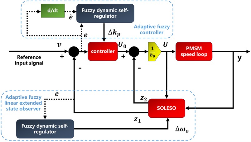
As indicated by Eq. (10) and Eq. (12), once the observer bandwidth and the controller bandwidth are set, their values remain fixed throughout the control process, making it difficult to simultaneously balance the trade-offs between system dynamic performance, steady-state characteristics, and disturbance rejection capabilities. Moreover, as discussed in Section 2, the PMSM systems are subject to various external disturbances in practical control applications. And the presence of internal parameter variations further complicates the control problem by introducing internal parameter uncertainties. This results in a lack of adaptability in both the controller and the SOLESO. To address these challenges, this paper proposes an enhanced LADRC method based on the fuzzy dynamic self-tuning mechanism, i.e., FDS-LADRC. To be specific, the fuzzy dynamic self-regulators are designed to adaptively optimize the parameters of the controller and the bandwidth of the SOLESO, respectively, thereby obtaining the adaptive fuzzy controller and the adaptive LESO, which can enhance the system’s adaptability and flexibility throughout the control process. This approach aims to achieve optimal coordination between the controller, SOLESO, and the controlled plant, resulting in improved control performance while avoiding the cumbersome and repetitive manual parameter tuning process. The overall control structure of FDS-LADRC is illustrated in Fig. 1. In the next subsection, the detailed design processes of fuzzy dynamic self-regulators are elaborated.
3.2. The design of fuzzy dynamic self-regulators
Fuzzy system, also known as fuzzy logic system, was proposed by Zadeh in 1965 [41]. It is an intelligent computing system based on fuzzy linguistic variables, fuzzy logic reasoning, and fuzzy set theory. The most significant feature of fuzzy systems is their ability to represent human prior experience in the form of IF-THEN linguistic rules, mimicking the human thought process, reasoning, and decision-making behaviors. Moreover, fuzzy logic can be employed to handle uncertainties within the system [42]. The basic components of a fuzzy system include the fuzzifier, knowledge base, rule base, fuzzy inference engine, and defuzzifier. The schematic diagram of a generic fuzzy system is shown in Fig. 2.
Above all, the specific configurations of fuzzy dynamic self-regulators are elaborated, with a Mamdani-type fuzzy structure adopted. On one hand, for the adaptive fuzzy controller’s fuzzy dynamic self-regulator, the error and its derivative of the closed-loop system serve as input variables, while the controller parameter variation is the output. Note that the universes of discourse for the input and output variables depend on practical control scenarios. Three fuzzy subsets are selected with respective semantic information, namely, negative, zero, and positive. Correspondingly, their membership functions are Z-shaped, triangular, and S-shaped functions, respectively. Moreover, the singleton fuzzifier, product inference engine, and center-of-sets defuzzification method are employed. An example of the membership functions for is illustrated in Fig. 3.
Fig. 2The schematic diagram of a classic fuzzy system
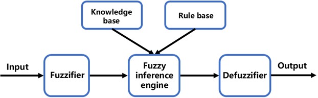
Fig. 3The membership function of ∆kp

Fig. 4The membership function of ∆ωo
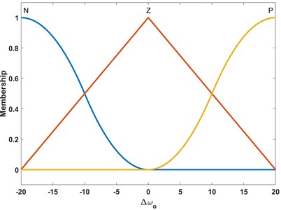
On the other hand, for the adaptive fuzzy LESO’s fuzzy dynamic self-regulator, the error of the closed-loop system is also chosen as the input variable and the variation of the bandwidth serves as the output. The fuzzy subsets and corresponding membership functions for and are the same as those used for tuning , i.e., . The singleton fuzzifier, product inference engine, and center-of-sets defuzzification method are employed as well. An example of the membership function for is illustrated in Fig. 4.
Since the controller is the most dominant component that affects the system performance, its parameters need to be precisely adjusted. Therefore, the tuning principle for is as follows: When the system response is in the rising phase ( is ), should be , meaning that should be increased. If the system response is in an overshoot state ( is ), in this case, should be , meaning that should be decreased. When the system response is in the steady-state ( is ), three scenarios are considered: (a) If is , indicating a decreasing trend in the overshoot, should be ; (b) If is , indicating that the system response is already stable, should be ; (c) If is , indicating that the error is increasing, should be . In summary, the fuzzy rule table for the tuning of is shown in Table 1.
Table 1The fuzzy rule table for tuning of ∆kp
N | Z | P | |
N | N | N | N |
Z | N | P | P |
P | P | P | P |
In addition to the controller, the bandwidth of the SOLESO also affects the system performance to a large extent. Specifically, when is sufficiently large, the observer can respond more quickly to changes in system states, thereby accelerating the convergence rate of state estimation and enhancing the system’s response speed. However, an excessively high may lead to a high overshoot in the system response, causing the observer’s state estimates to significantly exceed the actual state values. Moreover, it will amplify measurement noise, reduce the accuracy of state estimation and consequently degrade the control performance of the system. In severe cases, it may even lead to observer instability. Therefore, the tuning principle for is as follows: When the system response is in the rising phase ( is ), should be to enable the system to track the reference input more rapidly. When the system response is in an overshoot state ( is ), should be to ensure that does not become excessively large. When the system response is in a steady state ( is ), should also take a value tending towards zero to maintain system stability. The fuzzy rule table for the tuning of is shown in Table 2.
To sum up, the pseudocode of FDS-LADRC is shown in Table 3.
Table 2The fuzzy rule table for tuning of ∆ωo
N | Z | P | |
N | Z | P |
4. The stability analysis of the FDS-LADRC
In this section, the stability analysis of FDS-LADRC is presented. First, the stability of the SOLESO is analyzed. Subsequently, the stability of the closed-loop system is discussed.
4.1. The stability analysis of the SOLESO
Let the state error of the system be defined as . By combining Eq. (8) and Eq. (9), the state-space equation for the state error can be derived as:
Thus, the characteristic equation of Eq. (14) is:
Given that the bandwidth of the SOLESO is always greater than zero, it can be inferred from Eq. (15) that all poles are located at . Consequently, the SOLESO is BIBO stable.
Table 3The pseudocode of FDS-LADRC
Algorithm: FDS-LADRC |
1 Initialization: Setting initial parameters for the baseline controller, SOLESO, fuzzy dynamic self-regulators for both the controller and SOLESO, sampling time, and operational time. |
2 Main Control Loop: The continuous process running at the fixed sampling time. While operational time: 2.1 Performing forward control and obtaining the current output based on the current control quantity ; 2.2 Through SOLESO estimating system’s states and conducting compensation based on the current control quantity and the current output ; 2.3 Obtaining the current error and its derivative ; 2.4 Calculating the adaptive adjustments and based on the current error and its derivative by fuzzy dynamic regulators; 2.5 Performing the real-time update of the controller gain and the observer bandwidth . 2.6 end while |
4.2. The stability analysis of closed-loop system
According to Eq. (14) and Eq. (15), the control law can be rewritten as:
Substituting and into Eq. (16) and then into Eq. (8), the dynamics of becomes:
Defining the tracking error as , Eq. (17) can be rewritten as:
Consider the following positive definite Lyapunov function candidate:
Differentiating with respect to time yields:
According to Eq. (14), the error dynamics is:
Substituting Eq. (18) and Eq. (21) into Eq. (20) gives:
Applying Young’s inequality [43] to bound the cross terms in Eq. (22):
Substituting Eq. (23-27) into Eq. (22), we obtain:
Define the following constants: , , and . If , , and , then , , and . Thus, Eq. (28) can be rewritten as:
Assuming the rate of change of the disturbance is bounded, i.e., , it follows that:
where .
By the comparison lemma [44], the solution of Eq. (30) satisfies:
This indicates that the system states are ultimately uniformly bounded (UUB), Furthermore, if (i.e., in the absence of disturbance variation), the system is asymptotically stable.
5. Numerical simulations
In this section, a number of numerical simulations were conducted in MATLAB 2020b. Specifically, we utilized the traditional LADRC, nonlinear ADRC, SMC, a variant of FDS-LADRC, named IT2FDS, which adopted interval type-2 fuzzy systems to construct the fuzzy dynamic self-regulators, and a state-of-the-art control method named FSFOADRC as benchmarks for comparison. The simulated model of the PMSM speed loop is shown in Fig. 5. The model parameters are as follows: rated power 3 kW, stator resistance 0.958 Ω, damping coefficient 0.008 N∙m∙s, moment of inertia 0.003 kg∙m2, -axis inductance 12 mH, rated speed 1200 rpm, number of pole pairs 4, sampling time 10 μs, -axis inductance 5.25 mH, and effective flux linkage 0.1827 Wb.
For the fairness of simulations, the parameters for both the traditional LADRC and FDS-LADRC method were set to 50 and 200, respectively. For fuzzy dynamic self-regulators, the input domains of the error and its derivative were set to [–200, 1200] and [–10000, 10000], respectively, and the output domains of the variation of the control parameter and the variation of the observer bandwidth were set to [–10, 10] and [–50, 50], respectively. Regarding the nonlinear ADRC, was also set as 200. The other parameters were adjusted through trial and error for optimal performance, with specific values as follows: the velocity factor 200, the nonlinear factors 0.7, 0.5, and 0.8, the filtering factors 0.05, 0.05, 0.05, and 105. For the SMC, the parameters were also adjusted through trial and error for optimal performance, with specific values as follows: the sliding mode factor 60 and the factors of exponential approach law 200 and 300. For IT2FDS, the upper membership functions of the interval type-2 fuzzy system are identical to those of FDS-LADRC, while the lower membership functions are slightly smaller than the upper ones. For the FSFOADRC, was also set as 200. The other parameters were also adjusted through trial and error for optimal performance, with specific values as follows: 210, 8.5, and 0.75 (the fractional order of fractional-order ESO).
Fig. 5The simulated model of the PMSM speed loop

5.1. Speed comparison under no-load startup conditions (simulation)
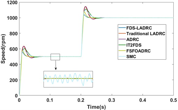
In this subsection, the simulations of speed comparison under no-load startup conditions of different methods are reported. At the beginning, the reference speed was assumed to be 500 rpm. Subsequently, the reference speed was increased to 1000 rpm at 0.2 s. The speed responses and the transient performance metrics are shown in Fig. 6 and Table 4, respectively.
As can be seen from Fig. 6 and Table 4, when compared with alternative control methods, the proposed FDS-LADRC demonstrates satisfactory transient performance under no-load startup conditions. It is capable of tracking the reference signal swiftly and smoothly. From a quantitative point of view, FDS-LADRC exhibits an overshoot of 13.87%, a peak time of 0.0096 s, and a settling time of 0.0219 s. These transient performance metrics outperforms those of its counterparts. Specifically, compared with nonlinear ADRC and LADRC, both of which employ fixed parameters, the adaptive fuzzy controller and the adaptive fuzzy LESO in FDS-LADRC have the ability to dynamically adjust the corresponding parameters in real time. This adaptive feature leads to its superior transient performance. In contrast to IT2FDS, although FDS-LADRC utilizes Type-1 fuzzy systems for parameter adjustment, it still achieves a more favorable control effect. In comparison with FSFOADRC and SMC, FDS-LADRC continues to deliver more desirable transient performance. Notably, due to the chattering phenomenon, the response of SMC is subject to certain fluctuations, whereas the response of FDS-LADRC exhibits little fluctuations.
Fig. 6The speed responses under no-load startup conditions (simulation)
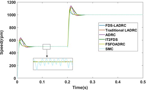
Table 4The transient performance metrics under no-load startup conditions (simulation)
Methods | Overshoot / % | Peak time / s | Settling time / s (2 %) |
FDS-LADRC | 13.87 | 0.0096 | 0.0219 |
LADRC | 24.69 | 0.0150 | 0.0351 |
ADRC | 27.42 | 0.0141 | 0.0295 |
IT2FDS | 21.23 | 0.0159 | 0.0358 |
FSFOADRC | 19.40 | 0.0098 | 0.0228 |
SMC | 17.81 | 0.0143 | 0.0375 |
In addition, the control quantities of all the methods under consideration are depicted in Fig. 7.
Fig. 7The control quantities under no-load startup conditions
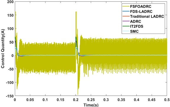
As shown in Fig. 7, the control quantity of FSFOADRC is significantly larger than that of its counterparts and exhibits noticeable chattering. We speculate that this phenomenon is attributed to the application of fractional calculus. On the other hand, compared with other methods, the control quantity of FDS-LADRC is relatively small and demonstrates a relatively smooth profile. This observation implies that the control cost associated with FDS-LADRC is comparatively lower. Consequently, we consider that FDS-LADRC has certain potential to be deployed in scenarios with limited computational resources, such as certain applications running on embedded hardware.
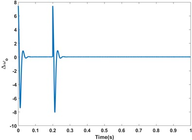
Moreover, the outputs of fuzzy dynamic self-regulators under no-load startup conditions are shown in Fig. 8 and Fig. 9, respectively.
Please note that due to space limitations, the control quantities of different methods and the outputs of fuzzy dynamic self-regulators are demonstrated in this case.
Fig. 8The output values of ∆kp under no-load startup conditions (simulation)
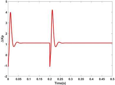
Fig. 9The output values of ∆ωo under no-load startup conditions (simulation)
5.2. Speed comparison under loaded startup conditions (simulation)
In this subsection, unlike in Section 5.1, the simulations of speed comparison under loaded startup conditions of different methods are reported. Specifically, a load torque of 2 N∙m was applied to the rotor of the PMSM at the start stage. Meanwhile, the reference speed was assumed to be 500 rpm, and then the speed was increased to 1000 rpm at 0.2 s. The speed responses and transient performance metrics of different methods under loaded startup conditions are illustrated in Fig. 10 and Table 5, respectively.
Fig. 10The speed responses under loaded startup conditions (simulation)
As shown in Fig. 10 and presented in Table 5, FDS-LADRC also obtains satisfactory control performance under loaded startup conditions. To be specific, the overshoot, peak time, and settling time of FDS-LADRC are 10.54 %, 0.0123 s, and 0.0245 s, respectively. These transient performance metrics are, for the most part, more outstanding than those of its competing methods. In addition, when comparing the results under loaded startup conditions with those under no-load startup conditions, it can be observed that the overshoots of both methods have decreased, while the settling time and peak time of the system have increased to a certain degree. We consider that that the following factors may account for these results: When the PMSM is started under loaded conditions, the inertia and damping effects exerted by the load can potentially elevate the damping ratio of the system. As a consequence, this leads to a reduction in the speed overshoot, but simultaneously increases the system’s response time.
Table 5The transient performance metrics under loaded startup conditions (simulation)
Methods | Overshoot / % | Peak time / s | Settling time / s ( 2 %) |
FDS-LADRC | 10.54 | 0.0123 | 0.0245 |
LADRC | 22.18 | 0.0171 | 0.0386 |
ADRC | 23.15 | 0.0179 | 0.0391 |
IT2FDS | 20.13 | 0.0169 | 0.0373 |
FSFOADRC | 15.87 | 0.0113 | 0.0248 |
SMC | 16.29 | 0.0147 | 0.0392 |
5.3. Speed comparison under sudden loading and unloading conditions (simulation)
In this subsection, the simulation models the scenario where the PMSM suddenly experiences a load disturbance. The simulation procedure is as follows: First, the PMSM was started under no-load conditions with a given speed of 500 rpm. At 0.2 s, a sudden load disturbance of 2 N∙m was applied to the motor. Subsequently, at 0.3 s, this load was suddenly released. The speed responses of different methods under this disturbance scenario are shown in Fig. 11.
Fig. 11Speed responses under sudden loading and unloading conditions (simulation)
As shown in Fig. 11, FDS-LADRC demonstrates remarkable disturbance rejection capabilities. This enables the output to quickly resynchronize with the reference speed after experiencing sudden increases or decreases in load disturbances. Specifically, at 0.2 s, when a load disturbance is abruptly introduced, the outputs of the traditional LADRC, ADRC, IT2FDS, and FSFOADRC drop to approximately 487 rpm, 484 rpm, 487 rpm, 490 rpm, and 478 rpm, respectively. Moreover, they require about 0.05 s, 0.05 s, 0.05 s, 0.025 s, and 0.04 s, respectively, to recover to the reference speed. In contrast, the output of FDS-LADRC only decreases to about 494 rpm and takes approximately 0.025 s to readjust back to the reference speed. Similarly, at 0.3 s, when the load disturbance is removed, FDS-LADRC demonstrates superior anti-disturbance ability compared to its counterparts. Through comparative analysis of these results, it is evident that FDS-LADRC exhibits superior performance and adaptability in resisting load disturbances.
5.4. Speed comparison under no-load startup conditions with measurement noise
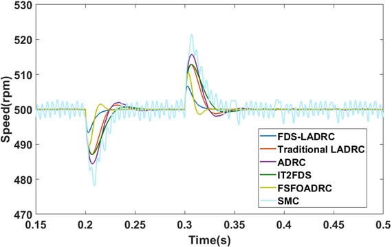
In this subsection, to assess the anti-noise ability, we carried out a simulation under no-load conditions. Specifically, the Gaussian white noise with a noise power of 0.005 and a sample time of 0.001 s was introduced into the system output. The speed responses under this noisy condition are presented in Fig. 12.
Fig. 12Speed comparison under no-load startup conditions with measurement noise

As shown in Fig. 12, when the measurement noise is introduced, the response of FDS-LADRC remains confined within approximately [480 rpm, 520 rpm]. In contrast, other control methods exhibit wider fluctuation ranges. For instance, the traditional LADRC fluctuates between about [450 rpm, 550 rpm], while FSFOADRC varies within about [470 rpm, 530 rpm]. These results demonstrate that despite the detrimental effects of measurement noise, the fuzzy dynamic self-regulators in FDS-LADRC can autonomously and collaboratively adjust parameters under uncertainty, enabling superior noise rejection performance.
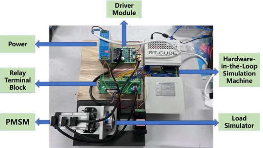
6. Real-world experiments
In this section, with the aim of further demonstrating the effectiveness and superiority of FDS-LADRC, we conducted a series of experiments on a real-world experimental platform. Here, the traditional LADRC was chosen as the benchmark for comparison. The experimental setup is shown in Fig. 13. Additionally, the parameters of the PMSM model employed in the experiment are listed as follows: rated power 0.1 kW, rated voltage 24 V, rated current 5.5 A, rated torque 0.32 N∙m, rated speed 1200 rpm, stator resistance 0.3 Ω, moment of inertia 0.003 kg∙m2, number of pole pairs 4, and line inductance 0.43 mH.
Since the real-world experimental platform has different model parameters compared to those in the simulation, the controller parameters need to be reset. For both the traditional LADRC and FDS-LADRC, the controller parameters are set as 0.3, and the bandwidths of the observer are set as 10. For fuzzy dynamic self-regulators, the input domains of the error and its derivative are set to [–50, 150] and [–500, 500], respectively, and the output domains of the variation of the control parameter and the variation of the observer bandwidth are set to [–0.05, 0.05] and [–3, 3], respectively.
Fig. 13The real-world experimental setup
6.1. Speed comparison under no-load startup conditions (experiment)
Similar to the process of Section 5.1, in this subsection, the PMSM was started under no-load conditions, with a reference speed set as 50 rpm at 20 s. Subsequently, the reference speed was raised to 100 rpm at 30 s. The speed responses of the two methods are shown in Fig. 14 and Fig. 15, respectively.
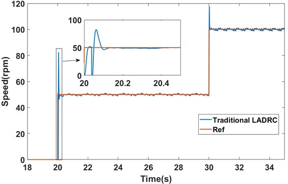
Fig. 14The speed response of the traditional LADRC under no-load startup conditions (experiment)
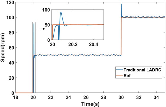
As shown in Fig. 14 and Fig. 15, under no-load startup conditions, the traditional LADRC takes approximately 0.1325 s to reach a steady state at 50 rpm. In contrast, FDS-LADRC achieves steady state in just about 0.0485 s. This indicates that FDS-LADRC has a response time approximately 0.084 s faster than traditional LADRC, significantly enhancing the system’s dynamic response capability. Furthermore, the traditional LADRC method exhibits an overshoot of approximately 83.27 %, whereas FDS-LADRC shows an overshoot of only about 32.44 %, which is approximately 50.83 % less than that of traditional LADRC. This demonstrates that FDS-LADRC achieves higher stability during the control process, effectively reducing the risk of system oscillations and instability caused by excessive adjustments, and enabling more precise control of motor speed.
6.2. Speed comparison under loaded startup conditions (experiment)
Similar to the process of Section 5.2, in this subsection, the PMSM was started under loaded conditions, with a reference speed set as 50 rpm at 20 s. Subsequently, the reference speed was raised to 100 rpm at 30 s. The load imposed on the motor is equivalent to 10 % of its rated load, i.e., 0.032 N∙m. The speed responses of the two methods are shown in Fig. 16 and Fig. 17, respectively.
Fig. 15The speed response of FDS-LADRC under no-load startup conditions (experiment)
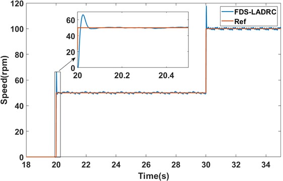
Fig. 16The speed response of the traditional LADRC under loaded startup conditions (experiment)
As shown in Fig. 16 and Fig. 17, under loaded startup conditions, the traditional LADRC method exhibits an overshoot of about 64.90 % and takes around 0.1425 s to reach steady state. In contrast, FDS-LADRC exhibits an overshoot of approximately 24.04 % and reaches steady state in just about 0.0545 s. Compared to the no-load startup conditions, both methods show a decrease in overshoot when starting under loaded conditions. Specifically, the overshoot of the traditional LADRC method decreases by about 18.37 %, while that of FDS-LADRC decreases by approximately 8.40 %. Additionally, the time taken to reach steady state increases by about 0.01 s for traditional LADRC and 0.006 s for FDS-LADRC. These results align with the phenomena observed in the simulations. Overall, FDS-LADRC outperforms traditional LADRC in terms of both overshoot and time to reach steady state, demonstrating superior transient performance.
6.3. Speed comparison under sudden loading and unloading conditions (experiment)
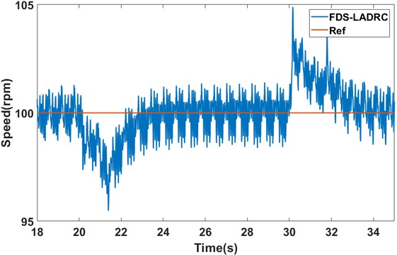
Similar to the process of Section 5.3, in this subsection, the PMSM was started under no-load conditions, with a reference speed set as 100 rpm. Subsequently, a load torque equivalent to 25 % of its rated load, i.e., 0.064 N∙m, was suddenly applied at 20 s. This load torque was then abruptly removed at 30 s. The speed responses of the two methods under this load disturbance condition are shown in Fig. 18 and Fig. 19, respectively.
Fig. 17The speed response of FDS-LADRC under loaded startup conditions (experiment)
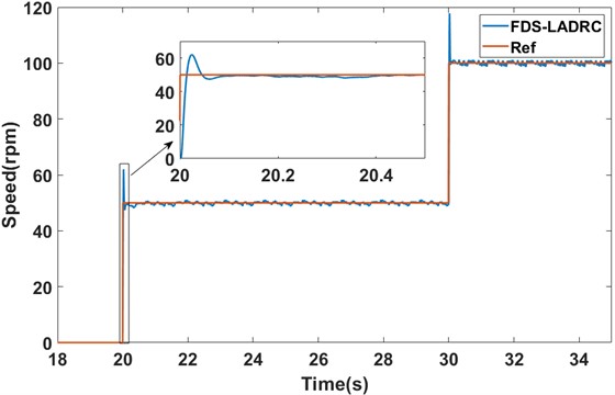
Fig. 18The speed response of the traditional LADRC under sudden loading and unloading conditions (experiment)
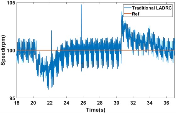
As shown in Fig. 18 and Fig. 19, there is a significant difference in recovery time to the steady state between the traditional LADRC method and FDS-LADRC when subjected to load disturbances. Specifically, when a sudden load disturbance is added, the traditional LADRC method takes about 4.5 s to return to the steady state, while FDS-LADRC only requires approximately 4 s, demonstrating faster recovery. Similarly, when this load disturbance is suddenly removed, the traditional LADRC method takes about 6 s to recover, whereas FDS-LADRC again only needs around 4 s to return to the steady state. It is noted that although FDS-LADRC exhibits slightly larger speed variations during both the addition and removal of the load disturbance, we believe this is primarily due to inherent limitations in the hardware (such as sensors and mechanical components) during the experiments, which are normal phenomena in a real-world experimental environment. Therefore, according to these experimental results, FDS-LADRC shows superior disturbance rejection performance when dealing with load disturbances.
Fig. 19The speed response of FDS-LADRC under sudden loading and unloading conditions (experiment)
7. Conclusions
In this paper, a novel control approach, namely FDS-LADRC, is proposed. To be specific, a LADRC-based control framework is designed for the PMSM speed loop model. On this basis, two fuzzy dynamic self-regulators are designed to adaptively and simultaneously adjust the controller parameters and the observer bandwidth. Additionally, the stability of the closed-loop system is analyzed. Moreover, the numerical simulation results show that: (1) Under no-load startup conditions, compared with the traditional LADRC, nonlinear ADRC, IT2FDS, FSFOADRC, and SMC, FDS-LADRC achieves a reduction in overshoot by 10.82 %, 13.55 %, 7.36 %, 5.53 %, and 3.94 %, respectively, and shortens the settling time by 0.0132 s, 0.0076 s, 0.0139 s, 0.0009 s, and 0.0156 s, respectively. (2) Under loaded startup conditions, relative to the same set of comparative methods, FDS-LADRC reduces the overshoot by 11.64 %, 12.61 %, 9.59 %, 5.33 %, and 5.75 %, respectively, while the settling time is decreased by 0.0141 s, 0.0146 s, 0.0128 s, 0.0003 s, and 0.0147 s, respectively. (3) In the presence of load disturbances, FDS-LADRC exhibits a smoother and faster recovery to the steady state compared with the aforementioned control strategies. (4) When subject to measurement noise, the response of FDS-LADRC is constrained within a narrower fluctuation range. These results collectively indicate that FDS-LADRC enables adaptive adjustment of controller parameters and observer bandwidth, which increases the degrees of freedom and enhances system flexibility. This not only eliminates the cumbersome manual tuning process but also effectively improves the system’s adaptivity, transient performance, disturbance rejection capability, and anti-noise ability. Furthermore, real-world experiments yielded results similar to those of numerical simulations, which further validate the effectiveness and superiority of FDS-LADRC in practical engineering scenarios.
In the future, we will move from manual fuzzy module design to data-driven autonomy: integrating deep neural networks with genetic algorithms for automatic fuzzy rule generation (including data-driven rule mapping and redundancy pruning) and introducing reinforcement learning with multi-objective rewards to dynamically adjust membership functions, adapting to extreme operating conditions. Additionally, we plan to explore hybrid control schemes by integrating FDS-LADRC with advanced strategies for coordinated operation. Furthermore, a key direction will be to tailor and validate the FDS-LADRC framework for various practical engineering applications, such as brake-by-wire systems in electric vehicles, aerospace actuators, and so on.
References
-
Q. Shi, Y. Dong, B. Li, and C. Zhou, “Analysis of electromagnetic vibration and noise of permanent magnet synchronous motor based on field-circuit coupling,” Journal of Vibroengineering, Vol. 24, No. 6, pp. 1188–1199, Sep. 2022, https://doi.org/10.21595/jve.2022.22266
-
F. Ding, A. Wang, and Q. Zhang, “Analysis of unidirectional and bidirectional magnetic-thermal coupling of permanent magnet synchronous motor,” Journal of Vibroengineering, Vol. 24, No. 8, pp. 1541–1555, Dec. 2022, https://doi.org/10.21595/jve.2022.22572
-
W. Ye et al., “Design optimization and manufacture of permanent magnet synchronous motor for new energy vehicle,” Energy Reports, Vol. 8, No. 15, pp. 631–641, Nov. 2022, https://doi.org/10.1016/j.egyr.2022.10.136
-
P. C. Berri, M. D. L. Dalla Vedova, P. Maggiore, and M. Scanavino, “Permanent magnet synchronous motor (pmsm) for aerospace servo mechanisms: Proposal of a lumped model for prognostics,” in 2018 2nd European Conference on Electrical Engineering and Computer Science (EECS), pp. 471–477, 2018.
-
K. Ahsanullah, E. Jeyasankar, S. K. Panda, R. Shanmukha, and S. Nadarajan, “Detection and analysis of winding and demagnetization faults in pmsm based marine propulsion motors,” in 2017 IEEE International Electric Machines and Drives Conference (IEMDC), pp. 1–7, May 2017, https://doi.org/10.1109/iemdc.2017.8002050
-
A. Mohanty, S. P. Parida, and R. R. Dash, “Modal response of sandwich plate having carbon-epoxy faceplate with different honeycomb core material and geometry considerations,” International Journal on Interactive Design and Manufacturing (IJIDeM), Vol. 18, No. 6, pp. 4223–4232, Jul. 2024, https://doi.org/10.1007/s12008-024-01975-z
-
S. P. Parida, P. C. Jena, S. R. Das, A. Basem, A. K. Khatua, and A. H. Elsheikh, “Transverse vibration of laminated-composite-plates with fillers under moving mass rested on elastic foundation using higher order shear deformation theory,” Proceedings of the Institution of Mechanical Engineers, Part C: Journal of Mechanical Engineering Science, Vol. 238, No. 20, pp. 9878–9888, Jul. 2024, https://doi.org/10.1177/09544062241256589
-
S. Sahoo, S. P. Parida, and P. C. Jena, “Dynamic response of a laminated hybrid composite cantilever beam with multiple cracks and moving mass,” Structural Engineering and Mechanics, Vol. 87, No. 6, pp. 529–540, Sep. 2023, https://doi.org/10.12989/sem.2023.87.6.529
-
Y. Cao et al., “Model reference adaptive system of permanent magnet synchronous motor based on current residual compensation without position measurement,” Actuators, Vol. 13, No. 11, p. 446, Nov. 2024, https://doi.org/10.3390/act13110446
-
A. Apte, U. Thakar, and V. Joshi, “Disturbance observer based speed control of PMSM using fractional order PI controller,” IEEE/CAA Journal of Automatica Sinica, Vol. 6, No. 1, pp. 316–326, Jan. 2019, https://doi.org/10.1109/jas.2019.1911354
-
K. D. Young, V. I. Utkin, and U. Ozguner, “A control engineer’s guide to sliding mode control,” IEEE Transactions on Control Systems Technology, Vol. 7, No. 3, pp. 328–342, May 1999, https://doi.org/10.1109/87.761053
-
Z. Zhang, X. Yang, W. Wang, K. Chen, N. C. Cheung, and J. Pan, “Enhanced sliding mode control for PMSM speed drive systems using a novel adaptive sliding mode reaching law based on exponential function,” IEEE Transactions on Industrial Electronics, Vol. 71, No. 10, pp. 11978–11988, Oct. 2024, https://doi.org/10.1109/tie.2023.3347845
-
D. Zhang, J. Hu, J. Cheng, Z.-G. Wu, and H. Yan, “A novel disturbance observer based fixed-time sliding mode control for robotic manipulators with global fast convergence,” IEEE/CAA Journal of Automatica Sinica, Vol. 11, No. 3, pp. 661–672, Mar. 2024, https://doi.org/10.1109/jas.2023.123948
-
J. Zhao, T. Zhao, K. Nie, and Y. Mao, “A fuzzy dual closed-loop control scheme for precision stabilized platform,” International Journal of Fuzzy Systems, Vol. 27, No. 6, pp. 1935–1950, Dec. 2024, https://doi.org/10.1007/s40815-024-01882-1
-
W. Yan, T. Zhao, and E. Q. Wu, “Prescribed-time fuzzy control for MIMO coupled systems with unknown structure and control direction: application to robotic arm,” IEEE Transactions on Automation Science and Engineering, Vol. 22, pp. 9013–9028, Jan. 2025, https://doi.org/10.1109/tase.2024.3496699
-
D. Mishra, P. C. Sahu, R. C. Prusty, and S. Panda, “A fuzzy adaptive fractional order-PID controller for frequency control of an islanded microgrid under stochastic wind/solar uncertainties,” International Journal of Ambient Energy, Vol. 43, No. 1, pp. 4602–4611, Dec. 2022, https://doi.org/10.1080/01430750.2021.1914163
-
A. R. Nasser, A. T. Azar, A. J. Humaidi, A. K. Al-Mhdawi, and I. K. Ibraheem, “Intelligent fault detection and identification approach for analog electronic circuits based on fuzzy logic classifier,” Electronics, Vol. 10, No. 23, p. 2888, Nov. 2021, https://doi.org/10.3390/electronics10232888
-
D. Mishra, P. C. Nayak, R. C. Prusty, and S. Panda, “An improved equilibrium optimization-based fuzzy tilted double integral derivative with filter (F-TIDF-2) controller for frequency regulation of an off-grid microgrid,” Electrical Engineering, Vol. 106, No. 2, pp. 2033–2055, Oct. 2023, https://doi.org/10.1007/s00202-023-02054-4
-
J. Zhao, T. Zhao, and N. Liu, “Fractional-order active disturbance rejection control with fuzzy self-tuning for precision stabilized platform,” Entropy, Vol. 24, No. 11, p. 1681, Nov. 2022, https://doi.org/10.3390/e24111681
-
Y.-J. Liu, W. Zhao, L. Liu, D. Li, S. Tong, and C. L. P. Chen, “Adaptive neural network control for a class of nonlinear systems with function constraints on states,” IEEE Transactions on Neural Networks and Learning Systems, Vol. 34, No. 6, pp. 2732–2741, Jun. 2023, https://doi.org/10.1109/tnnls.2021.3107600
-
L. Cao, Y. Pan, H. Liang, and C. K. Ahn, “Event-based adaptive neural network control for large-scale systems with nonconstant control gains and unknown measurement sensitivity,” IEEE Transactions on Systems, Man, and Cybernetics: Systems, Vol. 54, No. 11, pp. 7027–7038, Nov. 2024, https://doi.org/10.1109/tsmc.2024.3444007
-
J. Han, “From PID to active disturbance rejection control,” IEEE Transactions on Industrial Electronics, Vol. 56, No. 3, pp. 900–906, Mar. 2009, https://doi.org/10.1109/tie.2008.2011621
-
Z. Gao, “On the foundation of active disturbance rejection control,” (in Chinese), Control Theory and Applications, Vol. 30, pp. 1498–1510, 2013, https://doi.org/10.7641/cta.2013.31087
-
Z. Gao, “Active disturbance rejection control: a paradigm shift in feedback control system design,” in American Control Conference, p. 7 pp., Jan. 2006, https://doi.org/10.1109/acc.2006.1656579
-
A. Q. Al-Dujaili, A. F. Hasan, A. J. Humaidi, and A. Al-Jodah, “Anti-disturbance control design of Exoskeleton Knee robotic system for rehabilitative care,” Heliyon, Vol. 10, No. 9, p. e28911, May 2024, https://doi.org/10.1016/j.heliyon.2024.e28911
-
N. A. Alawad, A. J. Humaidi, and A. S. Alaraji, “Sliding mode-based active disturbance rejection control of assistive exoskeleton device for rehabilitation of disabled lower limbs,” Anais da Academia Brasileira de Ciências, Vol. 95, No. 2, Jan. 2023, https://doi.org/10.1590/0001-3765202320220680
-
A. I. Abdul-Kareem, A. F. Hasan, and A. A. Al-Qassar, “Rejection of wing-rock motion in delta wing aircrafts based on optimal LADRC schemes with butterfly optimization algorithm,” Journal of Engineering Science and Technology, Vol. 17, No. 4, pp. 2476–2495, 2022.
-
T. Wang et al., “Depth control of ROV using the improved LADRC based on nutcracker optimization algorithm,” Ocean Engineering, Vol. 309, p. 118370, Oct. 2024, https://doi.org/10.1016/j.oceaneng.2024.118370
-
J. Yan, C. Wang, Z. Duan, L. Shan, and S. Chi, “Enhanced two-degree-of-freedom integrated position tracking control strategy for PMSM servo systems based on SMCFO-LADRC,” IEEE Transactions on Transportation Electrification, Vol. 11, No. 1, pp. 3931–3941, Feb. 2025, https://doi.org/10.1109/tte.2024.3449143
-
H. Liu and S. Li, “Speed control for PMSM servo system using predictive functional control and extended state observer,” IEEE Transactions on Industrial Electronics, Vol. 59, No. 2, pp. 1171–1183, Feb. 2012, https://doi.org/10.1109/tie.2011.2162217
-
D. Shen et al., “Simulation investigation on pmsm servo system based on ladrc,” (in Chinese), Control Engineering of China, Vol. 23, pp. 51–55, 2016, https://doi.org/10.14107/j.cnki.kzgc.150894
-
Y. Cui, Y. Zhang, Z. Yin, and C. Bai, “Review of research on multi‐source disturbance suppression of permanent magnet synchronous motor drive system based on linear active disturbance rejection control,” Journal of Northeast Electric Power University, Vol. 44, No. 3, pp. 11–20, 2024, https://doi.org/10.19718/j.issn.1005-2992.2024-03-0011-10
-
F. Yang et al., “Complex coefficient active disturbance rejection controller for current harmonics suppression of IPMSM drives,” IEEE Transactions on Power Electronics, Vol. 37, No. 9, pp. 10443–10454, Sep. 2022, https://doi.org/10.1109/tpel.2022.3168367
-
M. Tian, B. Wang, Y. Yu, Q. Dong, and D. Xu, “Adaptive active disturbance rejection control for uncertain current ripples suppression of PMSM drives,” IEEE Transactions on Industrial Electronics, Vol. 71, No. 3, pp. 2320–2331, Mar. 2024, https://doi.org/10.1109/tie.2023.3265045
-
Y. Cui, Z. Yin, F. Gao, Y. Zhang, Y. Liu, and J. Liu, “Speed control of IPMSM based on series connection leading correction linear active disturbance rejection controller,” IEEE Transactions on Power Electronics, Vol. 39, No. 3, pp. 3096–3108, Mar. 2024, https://doi.org/10.1109/tpel.2023.3340699
-
C. Zhao and Y. Li, “Improved active disturbance rejection server control of permanent magnet synchronous motor,” (in Chinese), Manufacturing Automation, Vol. 46, No. 6, pp. 157–163, 2024, https://doi.org/10.3969/j.issn.1009-0134.2024.06.025
-
L. Qu, W. Qiao, and L. Qu, “An enhanced linear active disturbance rejection rotor position sensorless control for permanent magnet synchronous motors,” IEEE Transactions on Power Electronics, Vol. 35, No. 6, pp. 6175–6184, Jun. 2020, https://doi.org/10.1109/tpel.2019.2953162
-
R. Sancio, S. Pugliese, K. Debbadi, M. Liserre, E. Brescia, and G. L. Cascella, “Fuzzy based adaptive linear active disturbance rejection control for an high speed PMSM,” in IEEE 1st Industrial Electronics Society Annual On-Line Conference (ONCON), pp. 1–6, Dec. 2022, https://doi.org/10.1109/oncon56984.2022.10126818
-
Y. Li and Y. Chen, “The research of gain adaptive linear extended state observer (ALESO) based active disturbance rejection speed control for permanent magnet synchronous motor,” Electrica, Vol. 21, No. 1, pp. 20–31, Jan. 2021, https://doi.org/10.5152/electrica.2021.20006
-
H. Zhang, X. Lin, and J. Zhang, “Model-free recursive nonsingular terminal sliding mode control of PMSM speed loop based on fractional-order extended sliding mode disturbance observer,” (in Chinese), Information and Control, Vol. 53, No. 2, pp. 261–272, 2024, https://doi.org/10.13976/j.cnki.xk.2023.3041
-
L. A. Zadeh, “Fuzzy sets,” Information and Control, Vol. 8, No. 3, pp. 338–353, Jun. 1965, https://doi.org/10.1016/s0019-9958(65)90241-x
-
J. Zhao, P. Qin, Z. Mei, and T. Zhao, “A multiple attentions-based multilevel hybrid-guided deep fuzzy convolutional neural network for image recognition,” IEEE Transactions on Fuzzy Systems, Vol. 33, No. 8, pp. 2614–2628, Aug. 2025, https://doi.org/10.1109/tfuzz.2025.3572922
-
G. H. Hardy, J. E. Littlewood, and G. Pólya, Inequalities. Cambridge: Cambridge University Press, 1952.
-
H. K. Khalil, Nonlinear systems. Upper Saddle River, NJ: Prentice hall, 2002.
About this article

The authors have not disclosed any funding.
The datasets generated during and/or analyzed during the current study are available from the corresponding author on reasonable request.
Chun Wang: conceptualization and writing-review and editing. Jianjian Zhao: methodology, writing-original draft preparation, writing-review and editing, and software. Wei Zheng: writing-review and editing. Shaoda Xie: writing-review and editing. All authors have read and agreed to the published version of the manuscript.
The authors declare that they have no conflict of interest.
