Abstract
This study focuses on the stability control of surrounding rock in coal mine roadway. The finite difference method combined with FLAC3D software was adopted to establish numerical simulation model of the roadway roof, so as to analyze the influence of roof cutting height and roof cutting angle on the surrounding rock stress field. Through field tests, the bidirectional blasting excavation technology with energy-gathering pipes was used, combined with resistance-controllable support equipment. Differentiated monitoring point scheme was designed to monitor the changes in anchor cable tension and roof subsidence. The research results show that when the roof cutting height increases from 3 m to 6 m, the maximum stress of the roadway decreases by approximately 17 %, and the high-stress area shifts to the deep stable rock formation. When the roof cutting angle is adjusted from 0° to 10°, the maximum stress decreases by about 19.4 %, and the area of the high-stress zone is reduced to 11 % of the total cross-sectional area. When the distance behind the working face exceeds 100 m, the roof reaches a stable state under the action of support.
Highlights
- The finite difference method was adopted to establish numerical simulation model of the roadway roof, so as to analyze the influence of roof cutting height and roof cutting angle on the surrounding rock stress field.
- Through field tests, the bidirectional blasting excavation technology with energy-gathering pipes was used, combined with resistance-controllable support equipment.
- Differentiated monitoring point scheme was designed to monitor the changes in anchor cable tension and roof subsidence.
1. Introduction
Due to the complex and variable structure of coal and rock strata, the structure and strength of the rock mass will undergo dynamic changes during the excavation of the roadway, which is unfavorable to the stability of the seismic performance of the roadway [1, 2]. Therefore, in addition to meeting the strength requirements, the roadway support equipment should also have the ability to buffer large deformations. Considering the geological characteristics of the fully mechanized mining face, the simulation analysis of the support effect of different rock strata can provide an important basis for improving the seismic resistance of the roadway [3, 4]. To ensure the stability and safety of high-speed excavation roadways, the fully mechanized mining face in coal mines can adopt the coordinated support of constant resistance large deformation anchor cables and single hydraulic props, but the seismic performance needs to be tested. In coal mining, complete and reasonable data monitoring is a scientific means and basis for predicting the variation law of surrounding rock and designing support structures [5, 6]. In response to the relevant requirements for the quality supervision and acceptance of roadways, this paper adopts on-site testing methods, scientifically arranges monitoring points, and tests the mechanical performance of support equipment to ensure the rationality of roadway support.
The innovation points of this study mainly include two aspects: (1) Based on the characteristics of roadway construction, the Mohr-Coulomb model of FLAC3D is selected, and at the same time, the mechanical properties of unexcavated rock formations are simplified by combining the influencing factors of excavation. On the premise of ensuring simulation accuracy, the calculation efficiency is improved, which provides an efficient modeling idea for the stress field analysis of roadway roof. (2) A collaborative support scheme is proposed to solve the problem that traditional support is prone to failure due to stress concentration or vibration. A differentiated monitoring point layout is designed to accurately capture the changes in the mechanical parameters of surrounding rock, ensuring that the anchoring depth meets the load-bearing requirements.
2. Stress simulation of surrounding rock in roadway
2.1. The establishment of simulation model
In terms of numerical simulation research, this paper proposes to use the finite difference method to calculate the response characteristics of roof load-bearing, and realize the calculation of the overall stress of the roadway through FLAC3D software. FLAC3D is equipped with an explicit solver, which can divide the research object into multiple elements, assign corresponding constitutive functions according to different boundary conditions, and solve the constitutive functions using the finite difference algorithm. These elements can effectively simulate the deformation characteristics of materials under load, and achieve good results in the three-dimensional mechanical response analysis of the roof. The numerical simulation of the roadway can effectively predict the mechanical state of the surrounding rock under different conditions and accurately calculate the variation laws of stress and displacement, which is of great significance for the prediction and evaluation of support effects. According to the monitoring results, after the working face is exposed, the physical properties of the surrounding rock will change significantly, which is specifically manifested in the nonlinear plastic deformation of the rock formation. In addition, there are obvious rheological factors in the roadway surrounding rock; as the construction progresses, the roadway surrounding rock and the support structure can be regarded as a dynamic interaction model. Based on the characteristics of roadway formation construction, the Mohr-Coulomb model in FLAC3D is adopted for the roof analysis model. To improve calculation efficiency, the mechanical properties of the unexcavated rock formation are simplified with consideration of the influencing factors of excavation.
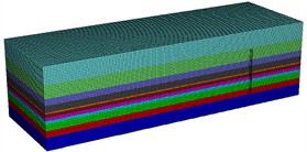
The three-dimensional model for roof analysis is established, and the mesh is divided layer by layer as shown in Fig. 1. In accordance with the distribution characteristics of the rock strata, the composition and thickness dimensions of the model are specified as follows: siltstone layer (2.0 m), upper coal seam (2.0 m), mudstone layer (1.0 m), fine-grained sandstone layer (4.0 m), and silt layer (2.0 m). Additionally, the floor rock strata are superimposed, with the composition and thickness dimensions of the model being: silt layer (4.0 m) and fine-grained sandstone layer (4.0 m).
Fig. 1The simulation model of surrounding rock
2.2. The influence of roof cutting height on the stress field
The essence of pressure unloading is the process of stress redistribution in the surrounding rock after the excavation of the roadway. The height of the roof caving directly affects the range and degree of stress release by altering the load-bearing structure of the roof rock mass. The stress field cloud diagrams of the roadway cross section under different roof caving heights are shown in Fig. 2. It can be clearly seen from the cloud diagram data that when the roof caving height is 3 m, the maximum stress value in the roadway reaches 1.397 MPa, and this stress peak is mainly concentrated in the two sides and the shoulder area of the roof of the roadway, which may cause local rock mass to be in a high stress state. When the roof caving height is increased to 6 m, the maximum stress value in the roadway drops to 1.158 MPa, which is approximately 17 % lower than the stress peak at a 3 m roof caving height, and the distribution range of the high stress area significantly shrinks. This indicates that increasing the roof caving height can effectively enhance the pressure unloading effect and reduce the stress level around the roadway. There is a positive correlation between the roof caving height and the migration and alleviation of the stress concentration area. As the roof caving height increases, the high stress area originally concentrated on the surface layer of the roof and the two sides of the roadway gradually shifts to the stable rock layer deep in the roadway, avoiding the direct overlap of the stress concentration area with the roadway support structure and reducing the risk of support failure due to local excessive stress. At the same time, the alleviation of stress concentration is not only reflected in the reduction of the stress peak but also in the decrease of the stress gradient. Under a 3 m roof caving height, the transition distance from the peak stress to the normal level around the roadway is only about 1.5m, with a sharp stress change. However, under 6 m roof caving height, the transition distance extends to 3 m, and the stress distribution becomes more gradual, effectively preventing brittle failure of local rock mass due to stress mutation.
Fig. 2The stress of the roadway cross section under different roof cutting heights (unit of MPa)
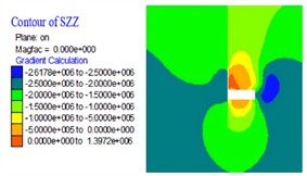
a) 3 m roof cutting height
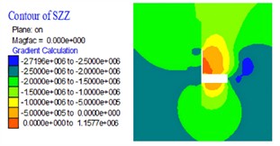
b) 6 m roof cutting height
2.3. The influence of roof cutting angle on the stress field
The stress field of the roadway cross section under different roof cutting angles are presented in Fig. 3. There exists a significant negative correlation between the increase in the roof cutting angle and the decrease in the peak stress within the roadway. When the roof cutting angle is 0°, the maximum stress value in the roadway attains 1.295 MPa. The high stress zone is primarily concentrated in the upper - middle portions of the two sidewalls of the roadway and the shoulder regions of the roof. The distribution area accounts for approximately 18 % of the total cross sectional area. During vertical roof cutting, the load bearing structure of the roof rock mass is not optimized effectively. After excavation, the energy of stress redistribution is released intensively in the shallow surrounding rock adjacent to the roadway, thus facilitating the formation of local stress superposition. When the roof cutting angle is adjusted to 10°, the maximum stress value in the roadway decreases to 1.054 MPa, which represents a reduction of approximately 19.4 % compared to the case of 0° roof cutting. Moreover, the area of the high stress region shrinks to 11 % of the total cross sectional area. Inclined roof cutting modifies the mechanical transmission path of the roof rock mass. As a result, part of the stress is transferred to the deep seated stable rock strata through the inclined roof cutting surface, thereby alleviating the stress bearing load of the surrounding rock around the roadway.
Fig. 3The stress of the roadway cross section under different roof cutting angles (unit of MPa)
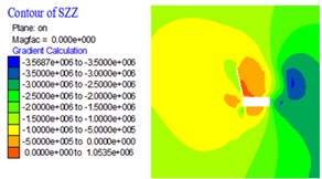
a) 0° roof cutting angle
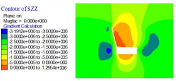
b) 10° roof cutting angle
3. Seismic resistance test
3.1. Installation and construction of anchor rods
To reduce the rate of sudden changes in the stress of the surrounding rock in roadway, engineering practices generally employ support equipment with controllable resistance, such as constant-resistance and large-deformation anchor cables. The anchor cable installation process must strictly comply with the following steps: first, pre-sleeve the constant resistor and W-shaped steel strip onto the anchor cable body in the designed sequence. Then, reserve the anchoring length at the tail of the anchor cable according to the borehole depth, push the cable body to the bottom of the borehole and ensure accurate positioning. The anchoring agent is applied by means of PVC pipe injection. Before injection, the anchoring agent must be stirred for 30 seconds to ensure uniform mixing. Only after the anchoring agent is completely injected into the borehole and solidified naturally can the drilling rig equipment be removed. To apply the prestress, after the anchoring system is cured for 12 hours, the loading operation shall be carried out through the constant resistor adjustment device. Combined with the geological structure characteristics of the surrounding rock of the roadway, the pre-tightening force is set to 28 tons to ensure the effective coupling between the anchor cable and the surrounding rock.
To prevent I-beams from tilting under the influence of residual blasting vibrations or surrounding rock vibrations, which would compromise the local support stiffness, steel meshes are fixedly connected to the I-beams. The selection and splicing of steel meshes must meet the following technical requirements: the length of a single steel mesh along the axial direction of the roadway is 2.3 m, and the overlapping length of two adjacent steel meshes shall not be less than 0.1 m. This ensures the overall crack resistance and load-bearing continuity of the steel mesh system. After the completion of roadway excavation and support, as the roof surrounding rock undergoes natural caving, the roadway system gradually reaches a state of stress equilibrium. For the roof caving areas, timely reinforcement measures must be taken, including but not limited to local shotcrete reinforcement (the thickness of shotcrete is determined based on the degree of surrounding rock fragmentation) and roadway surface shaping and restoration. Through these targeted reinforcement efforts, the overall stability of the roof surrounding rock is ensured, and support failure caused by local caving is avoided.
3.2. Layout design of monitoring points
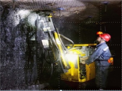
According to the structural characteristics of the coal mining face, the seismic parameter testing scheme is designed as shown in Fig. 4. Within the range of 100 m from the opening of the cutting roadway, one monitoring point is set every 20 m. Starting from the sixth monitoring point, the distance between monitoring points is set at 50 m. Hydraulic support monitoring covers single-column hydraulic supports and I-section steel. The first two hydraulic supports at the working face are both set as monitoring points, and subsequent monitoring points are installed every 8 hydraulic supports. The monitoring instruments to be installed at the monitoring points include anchor cable dynamometers, roof separation monitors, displacement sensors, pressure sensors, etc., which shall be installed in sequence according to the advancement conditions of the roadway. When measuring the roof displacement, it shall be ensured that the direction of the first and last measuring points is perpendicular to the direction of the measuring points on the left and right sides. The layout of monitoring points for bolt and anchor cable support has certain requirements on the size of the driven bolts: the length of the bolt embedded in the surrounding rock shall be more than 0.4 m, the remaining length of the bolt exposed outside the roadway shall be more than 0.5 m, and the remaining length of the bolt driven into the roof shall be more than 0.1 m. After the layout of monitoring points is completed, mark them with numbers in a timely manner to avoid the loss of marks during construction, which may affect the regularity of monitoring data. Before the installation of constant-resistance and large-deformation anchor cables, the borehole must undergo pre-treatment, and a dedicated drill bit with a diameter of 75 mm shall be used for reaming operations. To ensure the anchoring depth meets the load-bearing requirements, the axial extension length of the borehole reamed by the drilling rig must be more than 0.5 m. The on-site construction layout of the anchor rods and sensors is shown in Fig. 5. The spatial arrangement of the bolt and anchor cable components follows the following parameters: the spacing between components is set to 2 m, every 3 anchor cables form a group and are arranged in a linear manner. Meanwhile, W-shaped steel strips are used to connect the 3 anchor cables in the same group as a whole, so as to improve the coordinated load-bearing capacity of the support system.
Fig. 4Layout diagram of measurement points
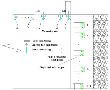
Fig. 5Installation of anchor rods and sensors
3.3. Analysis of monitoring results
Directional blasting with energy-gathering tubes is adopted for coal mine roadway excavation. The energy-gathering tubes are arranged in the blast holes, with a spacing of 0.5 meters between their ends, and both are aligned with the roadway formation direction. The blasting fuses must be routed and secured in strict accordance with the design parameters; during blasting, every 10 blast holes are detonated simultaneously. After the completion of blasting, the support of single hydraulic props is advanced. Thus, the variation laws of the measured anchor cable tension and roof settlement with the distance from the working face (lag distance) are shown in Fig. 6 and Fig. 7, respectively.
The test results of the changes in the tension of the anchor cables at different distances from the lagging working face show that the overall stability of the anchor cable tension is good. When the distance from the lagging working face is greater than –31 m, the tension of the anchor cable begins to increase sharply and reaches stability when the distance from the lagging working face is 0. The maximum deviation of the anchor cable tension at different lagging working faces is 17.37 kN. The anchor rods and anchor cables throughout the tunnel all exhibit good constant resistance effects.
Fig. 6The variation laws of the anchor cable tension
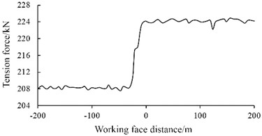
Fig. 7The variation laws of roof settlement
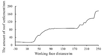
From the deformation law of roof subsidence under different distances from the working face, it can be observed that as the lag distance increases, the roof subsidence deformation shows a trend of intermittent increase. When the lag distance exceeds 100 m, the roof reaches a stable state under the combined action of bolts, anchor cables, and hydraulic supports. With the gradual removal of hydraulic props, the growth rate of roof subsidence exhibits significant nonlinear characteristics.
4. Conclusions
There is a positive correlation between the roof cutting height and the stress unloading effect of surrounding rock. Increasing the roof cutting height can significantly reduce the stress level around the roadway and expand the stress release range. The high-stress area shifts from the surface layer of the roof and the roadway side to the deep stable rock formation, avoiding the overlap between the stress concentration area and the support structure. At the same time, it extends the transition distance of stress from the peak value to the normal level, alleviating the brittle failure of rock mass caused by sudden stress changes. Inclined roof cutting can optimize the mechanical transmission path of the roof rock mass, transfer part of the stress to the deep stable rock formation, and reduce the bearing load of the surrounding rock around the roadway.
Resistance-controllable support equipment such as constant-resistance and large-deformation anchor cables has good stability. The maximum tension deviation under different lag distances is only 17.37 kN, showing a reliable constant-resistance effect throughout the process. The roof deformation law is clear: as the distance from the working face increases, the roof subsidence shows intermittent growth, and reaches a stable state when the lag distance exceeds 100 m. The differentiated monitoring scheme is effective. By using equipment such as anchor cable dynamometers and roof separation meters, combined with borehole pretreatment, the variation laws of anchor cable tension and roof subsidence with lag distance are obtained, providing data support for the evaluation of surrounding rock stability.
Future research can explore the influence of rock physical and mechanical properties on stress redistribution, quantify the effect of different excavation rates on the dynamic characteristics of stress redistribution by combining numerical simulation, laboratory tests, and on-site monitoring, and simultaneously investigate the coupling effect of the two to expand the application value of the research.
References
-
W. Zhang, G. Qiao, J. Wang, Y. Li, and X. Chu, “Study on seismic performance and modelling of large-grid shear walls with EPS concrete blocks,” Engineering Structures, Vol. 340, No. 1, p. 120679, Oct. 2025, https://doi.org/10.1016/j.engstruct.2025.120679
-
S. Kumar, A. Anand, R. Sarkar, and L. Nainegali, “A three-dimensional investigation on the efficacy of different configuration settings of micropiles in enhancement of seismic slope stability,” International Journal of Geosynthetics and Ground Engineering, Vol. 11, No. 5, p. 54, Sep. 2025, https://doi.org/10.1007/s40891-025-00659-2
-
Y. Yin, Y. Zhu, Y. Chen, Y. Qiu, and B. Chen, “Study on reasonable loading mode of small-scale roadway model and its application in mining engineering,” Energy Exploration and Exploitation, Vol. 42, No. 3, pp. 977–996, Oct. 2023, https://doi.org/10.1177/01445987231196615
-
X. Yuan, Y. Bi, M. Hao, Q. Ji, Z. Liu, and J. Bao, “Research on location estimation for coal tunnel vehicle based on ultra-wide band equipment,” Energies, Vol. 15, No. 22, p. 8524, Nov. 2022, https://doi.org/10.3390/en15228524
-
T. Ye et al., “Research on deformation monitoring method for surrounding rock in roadway based on an omnidirectional structured light vision sensor system,” Measurement, Vol. 255, No. 1, p. 117867, Nov. 2025, https://doi.org/10.1016/j.measurement.2025.117867
-
S. Li, P. Zhang, X. Hu, R. Wu, and L. Guo, “Seismic monitoring technology of driving and detection integrated of coal mine roadway,” in Journal of Physics: Conference Series, Vol. 2895, No. 1, p. 012055, Nov. 2024, https://doi.org/10.1088/1742-6596/2895/1/012055
About this article

The authors have not disclosed any funding.
The datasets generated during and/or analyzed during the current study are available from the corresponding author on reasonable request.
The authors declare that they have no conflict of interest.
