Abstract
In response to the lack of clear calculation methods for the normal section bearing capacity of circular piers strengthened by concrete jacketing in current design codes, this paper derives a calculation formula applicable to the normal section bearing capacity of strengthened circular piers under unloading conditions. The derivation is based on the relevant provisions of the Specifications for Design of Highway Reinforced Concrete and Prestressed Concrete Bridges and Culverts, incorporating the plane-section assumption and ultimate state theory. Finite element verification shows that the theoretical values agree well with the simulation results, with a maximum error of –1.55 %, and the results are conservative, meeting engineering safety requirements. In terms of impact resistance, increasing the thickness of the strengthening layer significantly enhances the pier's stiffness, reduces the displacement peak, and shortens the dynamic response time, shifting the damage mode from global damage to locally controllable damage. Parameter analysis indicates that the diameter of the main reinforcement and the spacing of the stirrups have a limited effect on the displacement response but play a key role in energy dissipation capacity: increasing the main reinforcement diameter effectively improves the total energy dissipation, while reducing the stirrup spacing enhances the confinement effect on the core concrete and improves energy dissipation efficiency. Considering both economy and construction feasibility, it is recommended to prioritize larger diameter main reinforcement and control the stirrup spacing within the range of 10-15 cm in impact-resistant design to achieve an optimal balance between performance and cost. Combined with a bridge strengthening project in Changchun, this paper summarizes key technical points, forming a theoretically complete and practically verified technical system for pier strengthening.
Highlights
- A formula for the eccentric compression capacity of circular piers strengthened by concrete jacketing is derived. For 20 cm and 10 cm thick jackets, theoretical errors are –1.55% and –0.13% vs. FEM, offering a conservative and efficient alternative to numerical analysis.
- Impact analysis of strengthened circular piers reveals that a thicker jacketing layer significantly increases stiffness, reduces peak displacement, shortens response time, and changes the failure mode from global to locally controllable damage.
- Main reinforcement diameter and stirrup spacing significantly affect impact energy dissipation, but have limited effect on peak displacement. Larger bar diameter increases absorption; smaller spacing improves confinement. Use larger bars with 10–15 cm spacing for optimal impact resistance.
- Key construction measures for circular pier concrete jacketing are presented, including interface roughening (shear reinforcement, epoxy) and self-compacting concrete (optimized mix, pouring), to ensure actual stress matches the theoretical model.
1. Introduction
Due to durability deterioration or increased load standards, many existing bridge piers suffer from insufficient bearing capacity. Concrete jacketing has become a common strengthening technique as it significantly enhances bearing capacity, stiffness, and durability. However, the current Specifications for Design of Highway Reinforced Concrete and Prestressed Concrete Bridges and Culverts only stipulate the calculation of bearing capacity for conventional sections. No specific theoretical formula is provided for calculating the eccentric compression normal section bearing capacity of circular bridge piers strengthened by concrete jacketing.
Currently, design engineers mainly rely on two approaches in practice: First, approximately treating the composite section as a whole section and applying ordinary concrete formulas. However, this method ignores the material differences and stress lag effect between new and old concrete, resulting in calculation results lacking a theoretical basis. Second, using refined finite element analysis. Although highly accurate, this approach involves complex modeling and is time-consuming, making it difficult to meet the tight schedules of urgent strengthening projects. Taking a bridge maintenance and strengthening project in Changchun as an example. In this project, the bridge required immediate strengthening due to insufficient pier bearing capacity found during inspection, and the schedule was extremely tight. Analyzing pier by pier using the finite element method would not meet the project schedule requirements. This dilemma highlights the urgency of establishing a set of theoretical formulas that ensure both calculation accuracy and rapid application.
In terms of the theory of concrete jacketing, Chinese and international scholars have conducted a series of studies. Yang Bin [1], based on existing codes, analyzed five failure modes of flexural members strengthened by concrete jacketing and proposed a normal section bearing capacity calculation formula applicable to both concrete thickening in the tensile and compressive zones. He also proposed a diagonal section shear calculation method for single-side thickening and three-sided jacketing strengthening through engineering case comparisons, improving calculation accuracy and safety. Li Hong [2], through tests on eccentrically compressed members strengthened by jacketing and bilateral enlargement, proposed modified values for the strength reduction coefficient of newly added longitudinal reinforcement in the Code for Strengthening Concrete Structures. Huang Yansheng [3] derived calculation formulas and curve equations for members with large and small eccentricities after strengthening under symmetric reinforcement and completed reliability analysis, pointing out that initial eccentricity, load ratio, and reinforcement ratio significantly affect the reliability index. The above studies all focus on rectangular sections, and their theoretical models rely on rectangular section assumptions, failing to consider the sectional characteristics and deformation behavior of circular piers, thus having limited applicability.
Regarding impact resistance, Zhao Wuchao [4] studied the dynamic response of piers under lateral impact and proposed a damage state assessment method based on sectional damage factors, indicating that pier energy dissipation consists of local and global dissipation. The combination of impact mass and velocity significantly affects the damage mechanism; axial force increases shear failure risk, and impactor stiffness has a substantial influence on impact force and response. Fan Wei [5] compared the impact resistance of UHPC and ordinary reinforced concrete piers through drop hammer tests and established a fiber nonlinear finite element and a two-degree-of-freedom spring-damper simplified analysis method. The authors of [6-9] conducted a series of studies on rockfall impacts on bridge piers in mountainous areas of China. By establishing experimentally validated refined finite element models, they systematically revealed the damage mechanism and dynamic response process of piers under impact loading. Regarding protection, it was proposed that measures such as optimizing strengthening layer thickness, smaller stirrup spacing, or installing external steel jackets can effectively improve pier impact resistance. For high-risk impact scenarios, active protection systems are recommended. The above research on pier impact resistance mainly focuses on ordinary reinforced concrete members, while studies on the dynamic response of circular piers strengthened by concrete jacketing under impact loading remain insufficient.
Furthermore, seismic fragility analysis of structures is an important means of evaluating their seismic resistance. Traditional parametric fragility methods usually assume that intensity measures and damage measures follow a log-normal distribution. However, this assumption often deviates from actual conditions under high-intensity ground motion levels. Addressing this limitation, Guo et al. [10] proposed a non-parametric seismic fragility analysis framework based on the probability density evolution method. This method does not require presupposed distribution assumptions and can fully consider the randomness of ground motions and the coupling effects of structural component damage. While improving analysis accuracy, it also significantly enhances computational efficiency, providing a more reliable theoretical basis for structural seismic resilience assessment. In terms of structural dynamic response control, Zhu et al. [11] explored the integration method of intelligent control and U-control, providing new ideas for active control strategies of bridge piers. In terms of remaining life prediction, Peng et al. [12] used KPCA and optimized LSSVM algorithms, offering data-driven methods for structural damage assessment and life prediction. In terms of environmental factor prediction, Gu et al. [13] combined multi-head attention mechanisms with hybrid deep learning models, providing algorithmic support for structural service environment analysis. In terms of damage identification, Haider et al. [14] proposed a multi-scale feature refinement method based on semantic attention networks, providing technical means for intelligent detection of structural surface damage. The above studies offer valuable references for the intelligent development of bridge pier strengthening design and maintenance.
Static bearing capacity is the fundamental guarantee of pier service performance, determining the structure's safety reserve under conventional loads, while the dynamic damage mechanism reflects its toughness and failure characteristics under extreme loads. Together, they constitute the dual indicators for evaluating the strengthening effect. Currently, there is a lack of clear theoretical methods for calculating the bearing capacity of circular piers strengthened by concrete jacketing, and research on their impact resistance is also insufficient. In view of this, this paper derives a calculation formula for the eccentric compression normal section bearing capacity applicable to circular piers after strengthening, and further analyzes the influence of strengthening layer thickness and reinforcement parameters on impact resistance, forming a complete technical system from static design to dynamic verification. Combined with engineering examples, key technical points are elaborated, aiming to provide theoretical basis and design reference for similar projects.
2. Basic assumptions
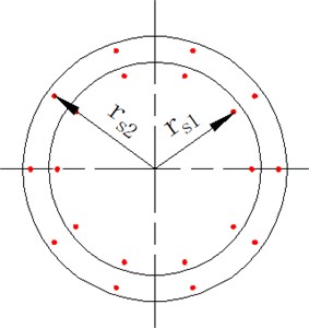
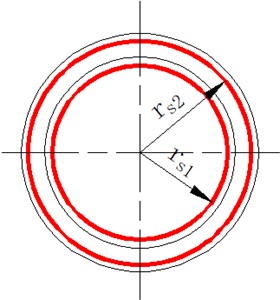
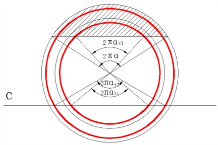
To establish the deformation compatibility relationship and material stress-strain physical relationships for the circular composite section after concrete jacketing, the following basic assumptions are adopted [15]: (1) The strengthened section and the original section deform compatibly, and the sectional deformation conforms to the plane-section assumption; (2) When the strengthened member fails, the ultimate compressive strain at the extreme compression edge of the concrete is taken as 0.0033; (3) The compressive stress distribution in the compression zone of concrete is represented by an equivalent rectangular stress block, with a stress intensity of ; (4) The tensile contribution of concrete in the tension zone is neglected, and tensile forces are solely borne by the steel reinforcement; (5) The original section and the strengthened section are each equipped with no fewer than six uniformly distributed longitudinal reinforcement bars around the periphery. The longitudinal reinforcement is equivalent to a thin-walled steel ring with an area of and a radius of for the original section, and a thin-walled steel ring with an area of and a radius of for the strengthened section.
Fig. 1Schematic diagram of equivalent steel rings
3. Derivation of calculation formula for normal section bearing capacity
3.1. Force equilibrium equations
From the force equilibrium condition along the longitudinal axis of the composite pier section:
From the moment equilibrium condition of all forces about the centroidal axis of the section:
where: is the resultant compressive force of concrete in the compression zone; is the resultant force of the original thin-walled steel ring; is the resultant force of the strengthening thin-walled steel ring; is the moment produced by the resultant compressive force of concrete about the centroidal axis; is the moment produced by the resultant force of the original thin-walled steel ring about the centroidal axis; is the moment produced by the resultant force of the strengthening thin-walled steel ring about the centroidal axis.
3.2. Resultant compressive force and moment of concrete in compression zone
The compression zone of the circular composite section after concrete jacketing remains a circular segment. The area of concrete in the compression zone is:
where: is the ratio of the central angle corresponding to the area of concrete in the compression zone of the circular composite section to ; is the total area of the composite section after jacketing.
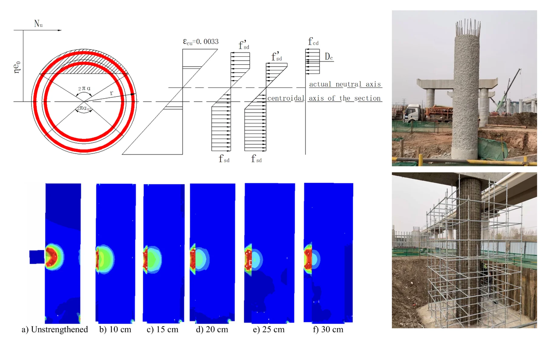
Fig. 2Force diagram of circular composite section under eccentric compression
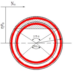
a) Section
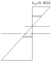
b) Strain
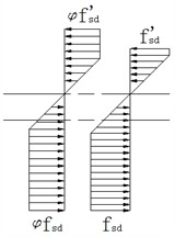
c) Steel stress
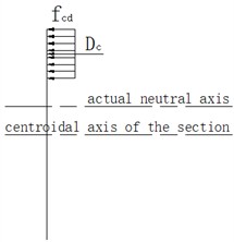
d) Equivalent rectangular stress block
The resultant compressive force and its moment about the centroidal axis are:
where: is the radius of the circular composite section; is the design value of the axial compressive strength of the new-to-old concrete composite section. Referring to the Code for Strengthening Concrete Structures [16], is approximately taken as , where and are the design values of axial compressive strength of new and old concrete, respectively. The differences in elastic modulus and strength between new and old concrete, as well as the influence of low-level initial loads such as self-weight on the stress distribution, are simplified through this weighted average method. This value determination method can comprehensively reflect the combined contribution of both materials.
3.3. Resultant force and moment of the strengthening thin-walled steel ring
From Ref. [15], the resultant force and its moment about the centroidal axis for the strengthening thin-walled steel ring are:
where: is the design tensile strength of the newly added reinforcement; is the utilization coefficient of newly added reinforcement, taken as 0.9. Under conditions where only low-level initial loads such as self-weight exist before strengthening, this coefficient can comprehensively compensate for the adverse effects of initial stress on the bearing capacity contribution of the newly added parts, thereby ensuring the applicability and safety of the formula in practical engineering. is the ratio of the central angle corresponding to the tension zone of the strengthening thin-walled steel ring to , approximately taken as ; when > 0.625, is taken as 0. is the ratio of the central angle corresponding to the compression zone of the strengthening thin-walled steel ring to , approximately equal to .
Substituting the values of and into Eqs. (6) and (7) yields:
3.4. Resultant force and moment of the original thin-walled steel ring
The region below axis is the tension zone of the steel ring. Based on geometric relationships, the central angle corresponding to the tension zone of the original thin-walled steel ring is:
Substituting yields:
Similarly, the central angle corresponding to the compression zone of the original thin-walled steel ring is:
The resultant force and its moment about the centroidal axis for the original thin-walled steel ring are:
Substituting Eqs. (11) and (12) into Eqs. (13) and (14) gives:
3.5. Basic formula for normal section bearing capacity calculation
Substituting Eqs. (4), (5), (8), (9), (15), and (16) into Eqs. (1) and (2) and rearranging yields the normal section bearing capacity calculation formulas:
where: ; is the amplification factor for eccentricity of axial compression members [17]; is the eccentricity of the axial force relative to the section centroid. When applying the formulas, can be assumed, and Eqs. (17) and (18) can be solved using an iterative method.
Fig. 3Schematic diagram of tension and compression zones of the equivalent steel ring
4. Strengthening calculation example
A reinforced concrete circular pier, 5 m high, with an original section diameter of 1.2 m, concrete strength grade C30, is uniformly reinforced with 2522 mm HRB400 longitudinal bars and 12 mm HRB400 stirrups spaced at 15 cm. Due to increased load rating, the normal section bearing capacity of the original pier is inadequate. The design axial force at the critical section is 5000 kN, and the design bending moment is 3000 kN·m. Concrete jacketing is proposed. The strengthening layer uses C40 concrete. Two schemes are considered: Scheme 1: Circumferential section enlargement with a thickness of 20 cm, uniformly adding 2520 mm HRB400 longitudinal bars in the strengthening layer, with 12 mm HRB400 strengthening stirrups spaced at 15 cm. Scheme 2: Circumferential section enlargement with a thickness of 10 cm, uniformly adding 2516 mm HRB400 longitudinal bars in the strengthening layer, with 10 mm HRB400 strengthening stirrups spaced at 15 cm. The eccentric compression normal section bearing capacity of the pier after strengthening needs to be calculated for both schemes.
Fig. 4Strengthened section diagrams (Unit: mm)
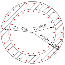
a) Scheme 1
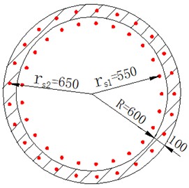
b) Scheme 2
To calculate the normal section bearing capacity of the strengthened pier, this paper employs a combination of theoretical formula calculation and numerical simulation for comparative verification. Theoretical calculations are based on the formula derived herein for the bearing capacity of circular sections after strengthening. Numerical simulation involves constructing a refined three-dimensional finite element model. The concrete of the original pier and the strengthening layer are discretized using solid elements. The material constitutive model considers compressive damage evolution and tensile cracking effects in concrete. The interface between the strengthening layer and the original structure is coupled mechanically using a surface-to-surface contact algorithm. The analysis adopts progressive loading, with the concrete compressive strain reaching the ultimate value of 0.0033 as the criterion for bearing capacity failure. The calculation results are shown in Fig. 5 and Table 1.
Fig. 5Numerical simulation calculation results
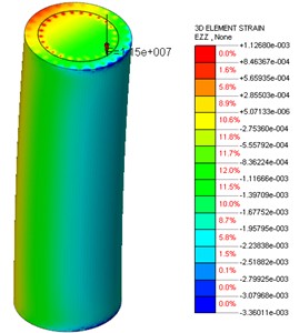
a) Strain results at ultimate limit state for Scheme 1
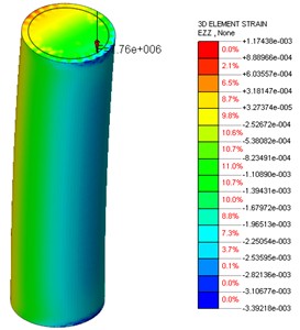
b) Strain results at ultimate limit state for Scheme 2
Comparative analysis of the eccentric compression normal section bearing capacity for the two strengthening schemes shows that the deviations between theoretical and numerical solutions are –1.55 % (Scheme 1) and –0.13 % (Scheme 2), respectively. The theoretical values are slightly lower than the simulated values, providing a conservative estimate and conforming to engineering safety reserve principles. These results validate the reliability of the formula derived herein for calculating the normal section bearing capacity of circular piers strengthened by concrete jacketing. The proposed formula supplements the missing calculation method for the bearing capacity of circular sections after strengthening in current design codes and simplifies the cumbersome refined numerical simulation calculations in engineering design, significantly enhancing the design efficiency for existing bridge strengthening projects.
Table 1Comparison of calculation results from different methods
Strengthening Scheme | Process parameter | Formula derivation (kN) | Numerical simulation (kN) | Relative error |
Scheme 1 (20 cm thickening) | 0.430 | 11325 | 11500 | –1.55 % |
Scheme 2 (10 cm thickening) | 0.415 | 7750 | 7760 | –0.13 % |
Note: Relative error = (Theoretical value - Simulated value) / Simulated value × 100 %. A negative value indicates that the theoretical calculation value is lower than the numerical simulation value, providing a conservative estimate | ||||
5. Study on impact resistance
In recent years, disasters such as floods, drifting objects, and vehicle collisions have occurred frequently, leading to an increasing number of bridge pier damage incidents caused by impact loads. Such impact loads are typically characterized by high amplitude, high strain rate, and transient dynamic features, which are difficult to accurately account for using traditional static design methods. Particularly for circular piers strengthened by concrete jacketing, clear calculation methods and assessment specifications for impact resistance are currently lacking. Therefore, based on impact dynamics theory and refined numerical simulation methods, this paper systematically investigates the dynamic response mechanism of strengthened piers under impact loading. It focuses on analyzing the influence of parameters such as strengthening layer thickness, strengthening main reinforcement diameter, and strengthening stirrup spacing on impact resistance. The aim is to provide a theoretical basis and design reference for relevant engineering practice.
5.1. Numerical simulation method and model establishment
For the study on the impact resistance of circular piers strengthened by concrete jacketing, a refined three-dimensional finite element model was established based on the ANSYS/LS-DYNA platform. This software has significant advantages in explicit dynamic analysis. Its built-in HJC concrete constitutive model can effectively simulate the dynamic response of materials under impact loading, including strain rate effects, damage evolution, and failure behavior, and has been widely used in research on the impact resistance of bridge piers.
The model consists of the original pier column, the new concrete strengthening layer, and a rigid impactor with a mass of 1.5 tons. The total height of the pier is 5 m, and the impact point is located at a height of 2 m from the pier bottom. To reasonably simulate the actual boundary conditions, the pier bottom is extended by 1 m, and translational degrees of freedom of all nodes on the bottom and side surfaces of the column base are constrained using the keyword *BOUNDARY_SPC_SET, simulating fixed-end conditions [4]. A downward axial uniformly distributed load is applied to the pier top to simulate the effect of the superstructure on the pier.
The HJC constitutive model, incorporating a failure criterion, is adopted for the concrete material. The keyword *MAT_ADD_EROSION is used with the principal strain as the failure criterion; elements are automatically deleted when their strain exceeds the set limit. The reinforcement employs the *MAT_PLASTIC_KINEMATIC elastoplastic kinematic hardening model and is embedded into the concrete using the keyword *CONSTRAINED_LAGRANGE_IN_SOLID. Regarding contact settings, the impactor is modeled using Solid164 elements, and an automatic surface-to-surface contact is defined between the impactor and concrete elements; an automatic surface-to-node contact is defined between the impactor and the Beam161 reinforcement elements.
In this paper, the basic mechanical parameters in the HJC model related to strength grade are determined according to the Specifications for Design of Highway Reinforced Concrete and Prestressed Concrete Bridges and Culverts, while the strength parameters, pressure parameters, and damage parameters mainly refer to the calibrated results of Ref. [18]. The key parameter values of the HJC model for concrete are shown in Table 2.
Table 2Key parameter values of the HJC model for concrete
(GPa) | (GPa) | (GPa) | (GPa) | EFMIN | |||||||
0.28 | 1.85 | 0.84 | 15 | 1.21 | 12 | 135 | 698 | 0.04 | 1.0 | 0.01 | 0.006 |
Load application involves pre-applying axial compression and self-weight using the dynamic relaxation method; subsequently, in the explicit dynamic analysis, an initial velocity of 30 m/s is assigned to the impactor [19]. The dynamic characteristics of the material are considered through the strain rate coefficient , which can reasonably reflect the material's dynamic response at an impact velocity of 30 m/s.
5.2. Influence of strengthening layer thickness on pier impact resistance
Using the original pier column dimensions and reinforcement from Scheme 1, while keeping the strengthening layer reinforcement pattern unchanged, five different thicknesses (10 cm, 15 cm, 20 cm, 25 cm, and 30 cm) were selected for concrete jacketing. The pier top displacement-time history response and damage state of the circular pier before and after strengthening were compared and analyzed.
Fig. 6Pier top displacement-time history curves for different strengthening layer thicknesses
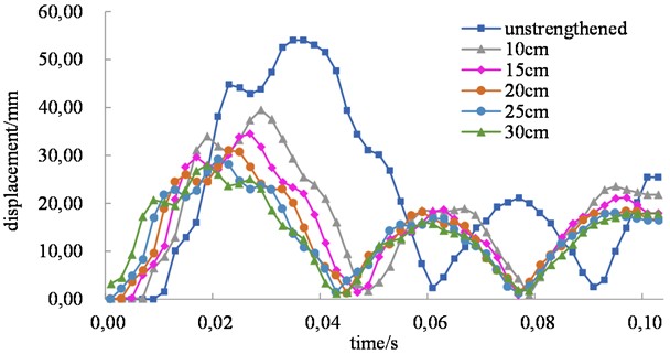
From the displacement-time history curves in Fig. 6, it is evident that as the strengthening layer thickness increases, the structural dynamic response exhibits two significant characteristics: the peak displacement decreases markedly, and the time to reach the peak is significantly shortened. This phenomenon primarily stems from the stiffness enhancement effect brought by the strengthening layer. A thicker strengthening layer substantially increases the flexural stiffness and overall moment of inertia of the structural section, enabling the structure to exhibit stronger deformation resistance under impact loading. Simultaneously, increased stiffness leads to a higher natural frequency of the structure, resulting in a more rapid dynamic response and thus shortening the time required to reach the maximum displacement.
Fig. 7Damage state of piers for different strengthening layer thicknesses

a) Unstrengthened

b) 10 cm

c) 15 cm

d) 20 cm

e) 25 cm

f) 30 cm
This paper uses a damage factor contour plot to describe the damage state of the structure, where red indicates severe damage and dark blue indicates no damage. From the evolution of damage modes shown in Fig. 7, it can be seen that as the thickness of the strengthening layer increases, the impact damage of the pier transitions from global damage to locally controllable damage. In the unstrengthened state, a large area of red appears near the impacted area of the pier shaft, accompanied by a small area of red at the pier bottom. When the strengthening layer thickness increases to 30 cm, the original pier column in the mid-height of the shaft is mostly light blue (minor damage), the red area is mainly distributed within the strengthening layer range, and only a very small area of light blue remains at the bottom, with the red area completely disappearing. This indicates only minor damage at the bottom, and the damage has been effectively confined to the peripheral area of the strengthening layer.
5.3. Influence of strengthening reinforcement on pier impact resistance
To systematically investigate the influence of strengthening layer reinforcement parameters on the impact resistance of circular piers, with the original pier dimensions and reinforcement from Scheme 1 as the basis, while keeping other strengthening parameters constant, the diameter of the strengthening main reinforcement (12, 16, 20, 25, 28 mm) and the spacing of the strengthening stirrups (5, 10, 15, 20, 25 cm) were varied for concrete jacketing. The pier top maximum displacement, damage state, and internal energy variation of the reinforcement under impact loading were compared and analyzed.
Fig. 8 presents a comparison of peak pier top displacements under different strengthening main reinforcement diameters and stirrup spacings. It can be observed that with an increase in main reinforcement diameter or a decrease in stirrup spacing, the peak pier top displacement only exhibits minor fluctuations. The displacement range among cases with varying main reinforcement diameters is 5.6 %, while that among cases with varying stirrup spacings is 1.2 %. This indicates that under the current strengthening scheme and extreme impact loading, simply adjusting reinforcement parameters has a limited effect on restraining the dynamic displacement of the pier top. This phenomenon primarily stems from two reasons. Firstly, the dynamic displacement response of the pier is mainly governed by the overall stiffness of the section. Simply increasing the main reinforcement diameter or reducing stirrup spacing contributes marginally to enhancing the section moment of inertia, thus failing to cause significant changes in overall stiffness and consequently having a minimal impact on the displacement response. Secondly, in the column-foundation connection of this model, the strengthening layer main reinforcement is not connected to the foundation. The flexural contribution of the strengthening reinforcement in the pier bottom area cannot be fully mobilized, forming a stiffness transition zone in this region, which weakens the restraining effect of reinforcement changes on pier top displacement.
Fig. 8Peak pier top displacement after strengthening
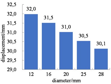
a) Peak pier top displacement for different strengthening main reinforcement diameters
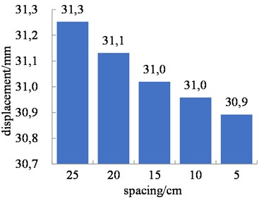
b) Peak pier top displacement for different strengthening stirrup spacings
Fig. 9Damage condition of pier strengthening layer

a) Strengthening main reinforcement 10 mm

b) Strengthening main reinforcement 28 mm

c) Stirrup spacing 25 cm

d) Stirrup spacing 5 cm
Based on the comparison of post-impact strengthening layer damage states shown in Fig. 9, it can be found that as the strengthening main reinforcement diameter increases or the stirrup spacing decreases, the damaged area of the concrete does not change significantly. Analysis indicates that under the set extreme impact load, the concrete in the strengthening layer rapidly crushes, and the strengthening main reinforcement of different diameters and stirrups of different spacings quickly enter the yield stage and even fail. This suggests that under the current strengthening scheme, relying solely on adjusting the main reinforcement diameter or stirrup spacing is insufficient to further enhance the ultimate impact bearing capacity of the structure, indicating a performance limit of this strengthening system under such load conditions [20].
However, from the internal energy-time history curves of the strengthening main reinforcement shown in Fig. 10, it is evident that although the reinforcement ultimately fails in all cases, the reinforcement parameters have a decisive influence on the energy dissipation capacity of the structure. Research indicates that increasing the main reinforcement diameter significantly enhances the total energy absorption capacity of the structure. The energy dissipation capacity of 28 mm main reinforcement can reach 8.04 times that of 10 mm main reinforcement, and this improvement effect is approximately linearly related to the increase in the cross-sectional area of the main reinforcement. The mechanism lies in the fact that thicker main reinforcement can dissipate more impact energy through greater plastic deformation. On the other hand, reducing the stirrup spacing also enhances energy absorption. The energy dissipation effect of the stirrup system with 5 cm spacing is 4.07 times higher than that with 25 cm spacing, but this influence exhibits a nonlinear characteristic. When the stirrup spacing exceeds 15 cm, the confinement effect and energy dissipation gain diminish significantly. This phenomenon occurs primarily because smaller stirrup spacing provides stronger confinement to the core concrete, effectively suppressing its lateral expansion and internal crack development, thereby enabling the structure to exhibit better ductility during the failure process and dissipate impact energy more efficiently through sustained deformation.
Fig. 10Internal energy-time history curves of strengthening reinforcement
a) Internal energy-time history curve of strengthening main reinforcement
b) Internal energy-time history curve of strengthening stirrups
Synthesizing the above results, under the strengthening system involved in this study, although adjusting reinforcement parameters can hardly alter the ultimate failure mode of the structure, it can significantly influence its energy dissipation capacity. Among these, the diameter of the main reinforcement dominates the overall dissipation potential, while the stirrup spacing optimizes dissipation efficiency through confinement effects. Based on comprehensive consideration of engineering economy and construction feasibility, it is recommended to prioritize larger diameter main reinforcement in impact-resistant design and control the stirrup spacing within the range of 10–15 cm. This achieves an optimal balance between impact resistance performance and engineering cost, thereby providing theoretical basis and practical reference for the impact-resistant design of similar structures.
To investigate the influence of parameter values on the calculation results, a sensitivity analysis was conducted on the strain rate coefficient C within a range of ±20 %. The results show that parameter fluctuations do not alter the main conclusions drawn, indicating the robustness of the conclusions.
6. Engineering application
Regarding the calculation method for the normal section bearing capacity of circular piers strengthened by concrete jacketing proposed in this paper, corresponding technical measures must be adopted in practical engineering applications to ensure consistency between theoretical calculations and the actual stress state. This section elaborates on relevant technical requirements based on a bridge maintenance and strengthening project in Changchun, providing engineering experience for similar projects.
6.1. Scope of application and load conditions
Since the derivation of the formula in this paper does not account for the initial stress in the section caused by existing loads, its scope of application is limited to pier strengthening projects where the bridge superstructure is unloaded. Therefore, active unloading of the superstructure through jacking or installation of temporary supports is required before strengthening, thereby eliminating the risk of debonding at the new-to-old concrete interface due to stress redistribution. In the case project, based on the bridge inspection conclusion, the main girders were deemed unfit for continued service. Hence, a phased rehabilitation scheme of “demolishing the superstructure → strengthening the substructure piers → constructing a new superstructure” was adopted. This scheme satisfies the applicable conditions of the theory. The strengthening construction employed concrete jacketing, using circumferentially encased C40 concrete with a layer thickness of 100 mm.
6.2. Measures to ensure interfacial bond
Fig. 11Treatment of new-to-old concrete interface (Construction site at Changchun, Jilin, China, 2023.4.10)
a) Roughening treatment of original pier concrete surface
b) Arrangement of shear reinforcement and application of epoxy resin bonding agent
This theoretical method is based on the assumption of perfect interfacial bond between new and old concrete, neglecting shear slip effects. Its applicability relies on the interfacial shear strength meeting force transfer requirements. In the case project, multiple construction measures were implemented according to the Specifications for Strengthening Design of Highway Bridges [21]: 1) The surface of the original pier concrete was roughened by chipping, achieving a surface roughness of no less than 6 mm, exposing coarse aggregate, and removing laitance; 2) Shear reinforcement (12 mm HRB400) was arranged circumferentially at 200 mm spacing and longitudinally at 150 mm spacing, with an anchorage depth of 160 mm, enhancing interfacial shear capacity through mechanical interlock; 3) Before pouring, the interface was flushed with high-pressure water and coated with an epoxy resin bonding agent, forming a composite bonding system.
6.3. Strengthening concrete construction technology
Addressing the challenge of confined workspace for circumferential encasement strengthening of circular piers, the case project utilized self-compacting concrete as the strengthening layer material. The material proportion and construction process were gradually optimized through multiple trial rounds. The thickness of the strengthened encased concrete layer was relatively small. Customized steel formwork was used, with two grouting holes reserved at the top edge and mid-height. Simultaneously, strict control was exercised over the raw materials, limiting the maximum coarse aggregate particle size to no more than 16 mm and requiring a slump flow value within the range of 660 to 750 mm to ensure concrete compactness [22].
Initial trials exposed significant issues, including circumferential cracks on the concrete surface after pouring, honeycombing, surface voids, segregation, and pipe blockage. Analysis identified several primary causes: imbalance in the cementitious material proportion, such as excessively high fly ash content without the addition of slag powder, leading to insufficient fluidity and color difference; poor aggregate gradation, with oversized crushed stone particles affecting filling capacity; a low water-binder ratio of 0.31 and an expansive agent dosage of 8 %, further exacerbating shrinkage cracking risk. Regarding construction techniques, dry formwork absorbing moisture, improper use of attached vibrators causing air bubbles, and segregation resulting from the delayed effect of the water reducer all negatively impacted concrete quality.
Fig. 12Strengthening concrete pouring effect diagram (Construction site at Changchun, Jilin, China, 2023.5.10)
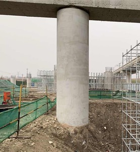
In response to these issues, corresponding improvement measures were implemented. Regarding material proportion optimization, the fly ash content was reduced to 12 %, slag powder with a density of 2.8 kg/m³ was introduced to improve color uniformity and fluidity, while the expansive agent dosage was decreased to 5 %. The sand ratio was adjusted to 45 %, and sand with a fineness modulus of 2.8 was used to enhance compactness. Regarding the admixture system, the synergistic effect of water reducer, retarder, and air-entraining agent was balanced to ensure concrete frost resistance and construction workability. Construction process improvements included eliminating mechanical vibration, using rubber hammers for auxiliary compaction, pre-wetting the formwork and spraying a release agent before pouring to prevent moisture loss, employing sectional pouring and manual supplementary pouring methods to address hard-to-fill areas near the pier top, strictly controlling the water reducer dosage to avoid delayed segregation, and strengthening mix quality control before concrete departure from the plant.
The application of self-compacting concrete necessitates a core focus on material proportion optimization, scientific admixture adaptation, and meticulous process control. Material-wise, a balance between the cementitious system and aggregate gradation is required. Admixtures should rationally coordinate water-reducing, retarding, and air-entraining functions. Process-wise, emphasis should be placed on formwork treatment and sectional pouring. Before construction, the mix proportion, slump flow value, and compactness indicators should be verified through tests on discarded pier columns, and specialized inspection and review procedures must be strictly followed. Subsequent work should integrate laboratory data and site feedback, involve collaboration with specialized manufacturers to refine details, and ultimately achieve a strengthening effect characterized by high frost resistance, high compactness, and uniform appearance.
7. Conclusions
1) A calculation formula for the eccentric compression normal section bearing capacity suitable for circular piers after strengthening is proposed. Leveraging the geometric simplification advantages of the thin-walled steel ring equivalent model, the formula considers the different material properties in the new-to-old concrete composite section and the utilization coefficient of newly added reinforcement. It can be solved iteratively during application, providing a theoretical basis for the strengthening design of circular piers.
2) The calculation accuracy and engineering applicability of the proposed formula are verified. For the two strengthening schemes with circumferential thickening of 20 cm and 10 cm, the errors between theoretical calculation values and simulation results are –1.55 % and –0.13 %, respectively (negative values indicate conservative results), conforming to engineering safety reserve principles. It can serve as an efficient alternative to refined finite element analysis.
3) The influence of strengthening layer thickness and reinforcement parameters on the impact resistance of piers is revealed. Increasing the strengthening layer thickness significantly enhances the section stiffness, reducing the peak pier top displacement and shortening the response time. The damage mode transitions from global damage to locally controllable damage. The diameter of the main reinforcement is a key factor determining the total energy dissipation capacity of the structure, while reducing stirrup spacing effectively enhances the confinement of the core concrete, optimizing dissipation efficiency. Based on a balance between performance and economy, it is recommended to adopt larger diameter main reinforcement when construction conditions permit and control the stirrup spacing within 10-15 cm.
4) A technical system from theoretical calculation to construction practice is formed. Based on a bridge maintenance and strengthening project in Changchun, the key technical points of concrete jacketing for strengthening circular piers were systematically summarized, providing a replicable full-process solution for similar projects. In the future, further model experimental validation can be conducted, along with in-depth research on strengthening-under-load conditions and different strengthening methods, to expand the applicability of the formula.
References
-
B. Yang, G. F. An, and C. L. Shan, “Calculation method of normal section bearing capacity of flexural members strengthened by enlarging section,” (in Chinese), Journal of Highway and Transportation Research and Development, Vol. 32, No. 6, pp. 81–88, 2015.
-
H. Li and S. C. Liu, “Study on normal section bearing capacity of RC members strengthened with enlarging section,” (in Chinese), Journal of Beijing Jiaotong University, Vol. 39, No. 4, pp. 96–100, 2015.
-
Y. S. Huang, H. Y. Song, and J. Cai, “Reliability analysis of reinforced concrete eccentric compression members strengthened with enlarging section,” (in Chinese), Engineering Mechanics, Vol. 27, No. 8, pp. 146–151, 2010.
-
W. C. Zhao and J. Qian, “Performance of reinforced concrete piers under lateral impact loading,” (in Chinese), Chinese Journal of Engineering, Vol. 41, No. 3, pp. 408–415, 2019.
-
W. Fan et al., “Impact test and simplified analysis method for circular UHPC piers under compressive force,” (in Chinese), China Journal of Highway and Transport, Vol. 32, No. 11, pp. 165–175, 2019.
-
X. Gu et al., “Research on the damage of mountain bridge pier subjected to rock-fall impact,” (in Chinese), Journal of Railway Engineering Society, Vol. 33, No. 3, pp. 72–75, 2016.
-
X. Y. Zhou, R. J. Ma, and A. R. Chen, “Reliability analysis on shear resistance performance of reinforced concrete column piers under rockfall impact,” (in Chinese), Journal of Vibration and Shock, Vol. 36, No. 7, pp. 262–270, 2017.
-
X. Y. Zhou, R. J. Ma, and A. R. Chen, “Analysis method for rockfall impact on reinforced concrete column piers,” (in Chinese), Journal of Harbin Institute of Technology, Vol. 50, No. 3, pp. 54–60, 2018.
-
H. Wu, F. S. Xiao, and R. W. Li, “Collapse analysis of double-column RC beam bridges subjected to rockfall impact,” (in Chinese), China Journal of Highway and Transport, Vol. 37, No. 5, pp. 94–107, 2024.
-
L. Guo, Y. Shen, M. Lyu, D. Zhang, and Z. Huang, “Non-parametric seismic fragility assessment of underground structures incorporating stochastic ground motion,” Soil Dynamics and Earthquake Engineering, Vol. 200, No. B, p. 109893, Jan. 2026, https://doi.org/10.1016/j.soildyn.2025.109893
-
Q. Zhu and H. Wang, “Primary Thought on the Incorporation of Intelligent Control and U-control (I-U-control),” ICCK Transactions on Sensing, Communication, and Control, Vol. 2, No. 3, pp. 132–146, Jul. 2025, https://doi.org/10.62762/tscc.2025.880778
-
Q. Peng, G. Li, C. Yang, X. Zhang, J. Na, and M. Li, “RUL prediction of the injection lance in copper top-blown smelting using KPCA and TSO-optimized LSSVM,” ICCK Transactions on Sensing, Communication, and Control, Vol. 2, No. 4, pp. 238–249, Nov. 2025, https://doi.org/10.62762/tscc.2025.978286
-
C. Gu, Y. Tan, X. Yin, X. Li, Y. Yang, and Y. Lv, “Enhanced air pollution prediction via Adam-optimized multi-head attention and hybrid deep learning,” ICCK Transactions on Intelligent Systematics, Vol. 3, No. 1, pp. 11–20, Jan. 2026, https://doi.org/10.62762/tis.2025.951370
-
A. U. Haider, A. Gazis, and F. Zahoor, “SemanticBlur: semantic-aware attention network with multi-scale feature refinement for defocus blur detection,” ICCK Transactions on Intelligent Systematics, Vol. 3, No. 1, pp. 21–31, Feb. 2026, https://doi.org/10.62762/tis.2025.879161
-
J. S. Ye and G. P. Li, Structural Design Principles. (in Chinese), Beijing: Communications Press Co., Ltd., 2019, https://doi.org/10.1201/9781351027700
-
“Code for design of strengthening concrete structure,” (in Chinese), China Architecture & Building Press, Beijing, GB 50367-2013, 2013.
-
“Specifications for design of highway reinforced concrete and prestressed concrete bridges and culverts,” (in Chinese), China Communications Press, Beijing, JTG 3362-2018, 2018.
-
G. M. Ren et al., “Parameter determination of HJC constitutive model for normal strength concrete,” (in Chinese), Journal of Vibration and Shock, Vol. 35, No. 18, pp. 9–16, 2016.
-
C. Q. Fang, S. Yang, and W. T. Xue, “Lateral impact resistance of concrete piers under dry-wet cycling corrosion environment,” (in Chinese), Concrete, Vol. 39, No. 6, pp. 67–71, 2017.
-
R. Xie, W. Fan, B. Liu, and D. Shen, “Dynamic behavior and vulnerability analysis of bridge columns with different cross-sectional shapes under rockfall impacts,” Structures, Vol. 26, pp. 471–486, Aug. 2020, https://doi.org/10.1016/j.istruc.2020.04.042
-
“Specifications for strengthening design of highway bridges,” (in Chinese), China Communications Press, Beijing, JTG/T J22-2008, 2008.
-
“Technical specification for application of self-compacting concrete,” (in Chinese), China Architecture and Building Press, Beijing, JGJ/T 283-2012, 2012.
About this article

The authors have not disclosed any funding.
The datasets generated during and/or analyzed during the current study are available from the corresponding author on reasonable request.
Xiaohui Cong: conceptualization, methodology, formal analysis, software, investigation, validation, writing-original draft. Yunlong Zhang: supervision, writing-review and editing. Haixia Zhao: methodology, data curation, writing-review and editing.
The authors declare that they have no conflict of interest.
