Abstract
The pressure pulsation is one of the key factors affecting instability operation and vibration of large mixed-flow pump units in pumped-storage power station. The unsteady flow field in a mixed-flow pump with different guide vane thicknesses was numerically simulated based on the standard k-ε turbulence model, the SIMPLE algorithm and the sliding mesh technique. By setting pressure measurement points, the pressure pulsation characteristics in the impeller inlet, outlet and the middle of guide vane were discussed and the influence of the guide vanes’ thickness on pressure pulsation was analyzed. The results show that the type of numerical simulation grid, turbulence model can accurately predict the internal flow characteristics of the mixed-flow pump. The dominant frequency of pressure pulsation was approximate to the impeller blade passing frequency. The thickness of the guide vane have less influence on pressure pulsation in the inlet of impeller, and have more influence on pressure pulsation in the middle of guide vane. Compared with the thinning guide vanes, the pressure pulsation amplitude of the thicken guide vane increase 7.8 %. Therefore, appropriately reducing the thickness of guide vane is beneficial to the stability of the internal flow of guide vane.
1. Introduction
Mixed-flow pumps are widely used in agricultural irrigation and drainage, municipal water supply and drainage, ships and warships water-jet propulsion, seawater desalinization system, circulating water system of thermal power generation, pumped-storage power station and nuclear power plants. With the increase of capacity and size of single-machine, the fluid exciting vibration is becoming one of the severe issues for large mixed-flow pump units and other turbo-machinery such as wind turbine [1-2], whose operation stability and vibration problems have drawn more and more attention [3-6]. However, for a long time, the researches have focused on the impact of unstable flow under off-design conditions on pump performance but neglected the performance degradation and damage of pumps caused by the rotor-stator interaction between impeller and guide vane. With the development of CFD technology in recent years [7-8], it is proved that gaining pressure pulsation mechanism of interior flow field through the research of interior unsteady flow characteristics of vane pump is one of the valid research methods. Gonzalez et al. investigated the pressure fields of a centrifugal pump by tests and numerical simulations and compared their numerical results with tests. The results indicated that pressure pulsation amplitude under blade passing frequency can be successfully acquired within a large flow range using numerical simulation method. Therefore they further verify the feasibility of numerical simulation method on the pressure pulsation research of centrifugal pumps [9-12]. Wang Fujun et al. studied pressure pulsation characteristics of non-steady flow fields of an axial-flow pump using transient flow analysis theory related to time and LES method [13-16]. Based on previous researches, this paper carries out numerical simulation for internal flow of a mixed-flow pump under different guide vane thickness using Fluent software, researches the pressure pulsation characteristics of impeller inlet and outlet and the middle flow field of guide vane, and analyses the influence rules of guide vane thickness on pressure pulsation of a mixed-flow pump, thus to provide reference for the optimal design and stable operation of mixed-flow pumps.
2. Research model
The major parameters of the mixed-flow pump studied in this paper are as follows: design flow rate 384 L/s, head 6 m, rotate speed 1450 r/min, specific speed 800, number of impeller blades 4, number of guide vane 7, design thickness of guide vane 5 mm, and the computational domain covers the whole pump segment from inlet segment of pump to outlet segment of elbow. Three-dimensional modeling is applied on mixed-flow pump using Pro/Engineer software. 3D models of both impeller and guide vane are shown in Fig. 1.
Fig. 1Three dimensional model: a) impeller, b) guide vane
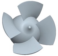
a)
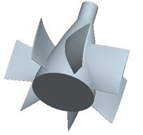
b)
Based on the design guide vane blade, reduces and increases 50 % of its thickness, respectively, without changing other design parameters, the influences of guide vane thickness on pressure pulsation in rotor-stator interaction flow field of impeller and guide vane was investigated in this paper. The guide vanes with different thickness are shown in Fig. 2.
Fig. 2Guide vane with different thickness: a) d= 2.5 mm, b) d= 5 mm, c) d= 7.5 mm

a)
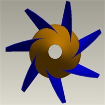
b)

c)
3. Numerical calculation
3.1. Meshing of the model
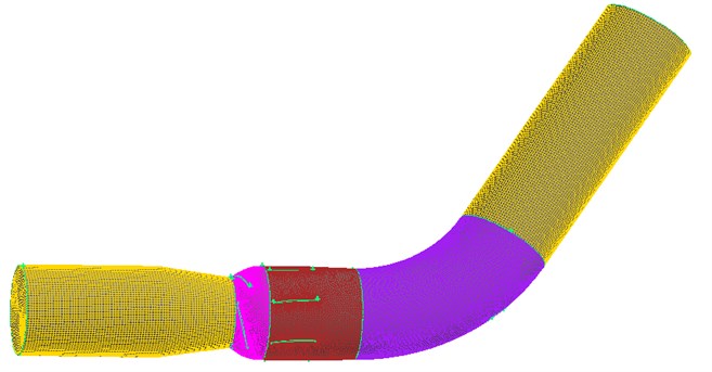
The total flow field comprises of inlet section, impeller, guide vane, bending section and outlet section. Due to the complex structure of computational domain in the internal flow field of the mixed-flow pump, unstructured meshing is adopted for impeller, guide vane and bending section, while structured meshing is adopted in the inlet section and outlet section, TGrid software is used in mesh interface of computational domain between impeller and guide vane for seaming, and local refinement is used in critical area. Under design condition, steady numerical simulation method is adopted to calculate pump head so as to minimize the impact of mesh size on computational accuracy. When meshes are more than 3,000,000 and the variation range of head is within 1 %, it is thought that mesh is independent. The meshing of total flow field is shown in Fig. 3. After numerical calculation, the meshes amount of inlet section, impeller, guide vane, bending section and outlet section are 84360, 838810, 1848112, 759787, 111100 respectively, and 3642169 altogether.
Fig. 3The whole flow field after meshing
3.2. Control equation
According to the mass and momentum conservation, the standard model - is used, the transport equation with turbulent kinetic energy and turbulent kinetic energy dissipation rate is as follow:
where is the turbulent viscosity, , and are the empirical constants, is the turbulent kinetic energy generated by mean velocity gradient, and are the Prandtl numbers corresponding to turbulent kinetic energy k and dissipation rate ε, respectively. Model constant values are as follows: 0.09, 1.44, 1.92, 1.0, 1.3.
3.3. Calculation and boundary conditions
Based on CFD commercial software FLUENT, three-dimensional incompressible N-S equation is used to describe internal flow of pump, and the closed equation set of the standard - turbulence model is adopted to solve incompressible N-S equation with SIMPLEC computational method. Non-slip boundary condition is applied on the wall surface, standard wall surface function is used near wall area, while the inlet adopts speed inlet boundary condition and the outlet adopts free outflow boundary condition.
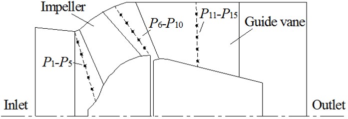
Unsteady numerical simulation is carried out based on the computational result convergence of three-dimensional steady turbulence. Convergences at all time constitute unsteady solution, namely, pressure pulsation of flow field is calculated in accordance with the change process of pressure and speed of the whole passageway with time. The time step is set as 3.4482×10⁻⁴ s. It needs 120 steps to rotate a circle when each time step impeller rotates 3°. 5 monitoring points of pressure pulsation are set on impeller inlet and outlet, and middle guide vane, respectively, as indicated in Fig. 4. The operating condition in this paper is the design condition of mixed-flow pump.
Fig. 4Location diagram of pressure monitoring points
4. Experimental verification
4.1. Test rig
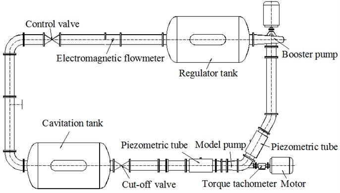
According to the design three-dimensional model, manufacturing a mixed-flow pump experimental model, as shown in Figure 5. A closed performance test rig of mixed-flow pump (as shown in Fig. 6) is set up to verify the accuracy of the numerical simulation. The test rig is suitable for diameter 250~400 mm axial flow pump, mixed-flow pump and model device, it is mainly composed of control valve, electromagnetic flowmeter, regulator tank, booster pump, inlet and outlet piezometric tube, cavitation tank, torque tachometer and model pump, etc. The regulator tank is used to supply water and harmonize system pressure and the booster pump is primarily used for pressurized when the the model pump speed is too low.
During the experiment, the pressure in the inlet and outlet piezometric tube is measured using pressure transducer and the head is obtained by calculating the inlet and outlet pressure difference. The rotating speed, torque and shaft power of the model pump are measured using a torque tachometer, the flow rate is measured by an electromagnetic flow-meter, and all of the data are collected by computer automatically. The test facilities and measure methods abide by the measurement requirements that are described in [17]. The measurement errors of tachometer and flow meter are ±0.2 % and ±0.5 %, respectively, the accuracy level of pressure gauge is 0.4, and the test rig reaches the level 1 accuracy requirement.
Fig. 5Experimental model: (a) impeller, (b) guide vane
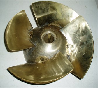
a)
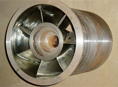
b)
Fig. 6Diagram of the test device
4.2. Test result and analysis
Overall characteristic curves obtained by mixed-flow pumps test and numerical simulation were shown in Fig. 7.
Fig. 7Comparison between experimental and numerical simulation results
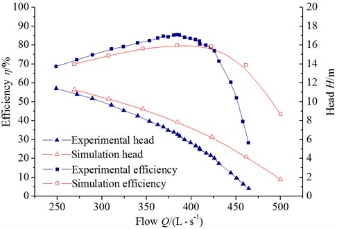
It can be seen from Fig. 7 that the calculated head is higher than model test results, while its efficiency is slightly less. Under low flow operating condition, the result of numerical simulation is close to test result. The minimum errors of head and efficiency can reach 2.45 % and –2.60 %, respectively, while the head error at design point is 16.7 %, and the efficiency error is 6.5 %. The error under large flow rate is larger due to the serious internal flow cavitation of the mixed-flow pump, which shows the numerical simulation near design operation condition and under low flow operation condition is more in line with the actual operation condition of pump. Due to the local structure difference for pumps used in the comparison of numerical calculation model and test measurement and other effects such as mesh quality, it is inevitable to avoid the error of numerical calculation and test measurement. However, as a whole, the head and efficiency of numerical simulation are generally consistent with the performance of test measurement, which indicates that the mesh type and turbulence model adopted in this calculation can accurately predict the overall characteristic of the mixed-flow pump.
5. Results of numerical simulation and discussion
5.1. Distribution of unsteady static pressure
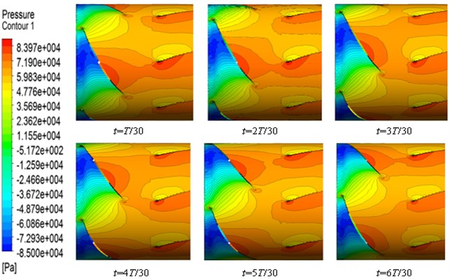
Due to the interference between impeller and guide vane, the interaction between internal pressure field of impeller and static pressure field of guide vane exists. The change process of the interaction pressure between impeller and guide vane under design guide vane thickness with time is shown in Fig. 8, it can be seen that the rotor-stator interaction between rotating impeller and static space guide vane causes the disorder of internal flow field of annular space between impeller outlet and space guide vane inlet, and with the rotating of impeller, higher-pressure zone formed in impeller outlet pressure surface and low-pressure zone formed in impeller outlet suction surface continuously exchange pressure energy with the inlet flow field of guide vane, where periodic pressure pulsation is formed, and higher-pressure zone and low-pressure zone emerge alternately. Meanwhile, with the interference of static space guide vane to outlet flow field, periodic pressure pulsation also emerges in the flow field outlet of impeller.
In the different thickness of the guide vane, the high-pressure zone in the interaction flow field is increase obviously with the increase of vanes thickness. When the vanes thickness increase to 50 %, as the vanes flow channel is narrowed and the flow velocity is increased, the most disorder flow field appears in the annular space between impeller outlet and space diffuser inlet, but change of the pressure fluctuation in the interaction flow field is basically the same trend over time. In order to thoroughly investigate the influence of guide vane thickness on pressure pulsation in the interaction flow field, it is necessary to analyze the time-domain and amplitude of the pressure pulsation.
Fig. 8Pressure change process in interaction flow field
5.2. Analysis of pressure pulsation
Pressure pulsations at 15 points in impeller inlet and outlet and middle of guide vane in the mixed-flow pump are obtained through unsteady numerical simulation, and the results are expressed with pressure coefficients. The expression of pressure coefficient is as follows:
where is the difference between monitoring pressure and average pressure Pa, while is the peripheral velocity of impeller outlet m/s.
Fig. 9 is the comparison figure between pressure pulsation time domain of impeller monitoring point with different guide vane thickness and pressure amplitudes at every monitoring point. It can be seen that the guide vane thickness has little impact on pressure pulsation of impeller inlet of the mixed-flow pump, and the pressure coefficient at this monitoring point almost has no change, but the impact of guide vane thickness on pressure amplitude close to casing is slightly larger than that of hub. The peaks and valleys of pressure pulsation of the impeller inlet are consistent with the number of blades, 4, namely, 4 peaks and valleys emerge, whose main frequency is blade passing frequency, which indicates that pressure pulsation is related to the number of impeller blades.
Fig. 10 is the comparison between pressure pulsation of impeller monitoring point with different guide vane thickness and pressure amplitudes at every monitoring point. It can be seen that 4 peaks and valleys also emerge for pressure pulsation at the impeller outlet, which is the same as the number of impeller blades, which indicates that the number of blades is also the main factor affecting pressure pulsation frequency of impeller outlet. The pressure coefficient at the impeller outlet increases with the increasing of guide vane thickness, and the pressure amplitude also rises with the increasing of guide vane thickness. The pressure amplitude reaches the maximum when guide vane thickness increases by 50 %, but the variation of pressure amplitudes along radial direction at each monitoring point are roughly consistent.
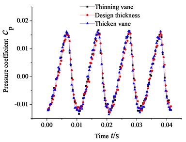
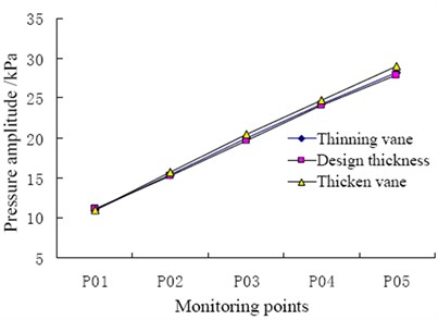
Fig. 11 is comparison between pressure pulsation of impeller monitoring point with different guide vane thickness and pressure amplitudes at every monitoring point. It can be seen that the guide vane thickness has obvious impact on internal pressure coefficient and pressure pulsation amplitude of guide vane: with increasing of guide vane thickness, the pressure coefficient in the middle of guide vane increases, as well as the pressure pulsation. Compared with reduction vane, the internal pressure amplitude of thicken vane increases relatively considerably, by up to 7.8 %. Meanwhile, obvious 4 peaks and valleys emerge, the same as that of number of impeller blades, due to the impact of the interaction flow field of impeller and guide vane on internal pressure pulsation of guide vane. Blade passing frequency plays dominant role in the interior of guide vane. In a word, guide vane thickness has large impact on the interior of guide vane and flow field downstream, so appropriately reducing the thickness of guide vane blades is beneficial to the stability of the internal flow of guide vane.
Fig. 9Pressure pulsation at impeller inlet
a) Time domain diagram at point
b) Pressure amplitude
Fig. 10Pressure pulsation at impeller outlet
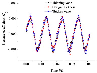
a) Time domain diagram at point
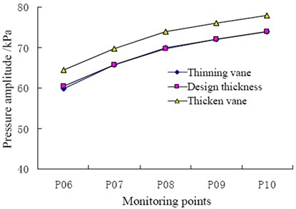
b) Pressure amplitude
Fig. 11Pressure pulsation in middle of guide vane
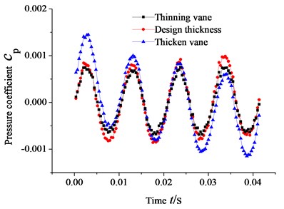
a) Time domain diagram at point
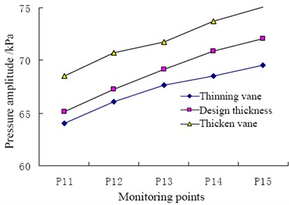
b) Pressure amplitude
6. Conclusions
The main frequency of internal pressure pulsation of mixed-flow pump in large pump station is related to the number of impeller blades, which also mainly affects the peaks and valleys number of pressure pulsation, and blade passing frequency plays the dominant role all the time, which indicates that the number of blades is the key factor affecting pressure pulsation frequency, so the number of impeller blades should be carefully selected in the hydraulic design of a mixed-flow pump.
The guide vane thickness mainly affects the pressure pulsation of impeller outlet and internal flow field of guide vane, but it has less impact on the inlet flow field of impeller. With the increasing of guide vane thickness, flow channel area reduces, which results in the increase of the shock loss of guide vane inlet and obvious increase of the internal pressure pulsation amplitude of guide vane. Thus appropriately reducing the thickness of guide vane is beneficial to the stability of the internal flow of guide vane and the safe operation of large pump station units.
References
-
Shi Weidong, Zou Pingping, Zhang Desheng, et al. Unsteady flow pressure fluctuation of high-specific-speed mixed-flow pump. Transactions of the CSAE, 2011, Vol. 27, p. 147-152.
-
S. Varbak Nese, O. Kilic, T. C. Akinci Analysis of wind turbine blade deformation with STFT method. Energy Educ. Sci. Technol. Part A, Vol. 29, 2012, p. 679-686.
-
Masahiro Miyabe, Akinori Furukawa, Hideaki Maeda, et al. Investigation of internal flow and characteristic instability of a mixed flow pump. ASME Conf. Proc. FEDSM, 2009, Vol. 1, p. 315-321.
-
Cheng Li, B. P. M. Van Esch Blade interaction forces in a mixed-flow pump with vaned diffuser. ASME Conf. Proc. FEDSM, 2009, Vol. 1, p. 165-173.
-
Zhu Rongsheng, Yan Hao, Fu Qiang, et al. Numerical calculation of characteristics of tubular pump internal pressure pulsation. Journal of Hydroelectric Engineering, Vol. 31, 2012, p. 220-225.
-
Zhang Desheng, Shi Weidong, Chen Bin Unsteady flow analysis and experimental investigation of axial-flow pump. Journal of Hydrodynamics, Ser. B, Vol. 22, 2010, p. 35-43.
-
S. Toksoz, G. Coskun, C. Celik, E. Buyukkaya, H. S. Soyhan, F. Halici Modeling of an HCCI engine by using CFD and detailed chemical kinetic model. Energy Educ. Sci. Technol. Part A, Vol. 29, 2012, p. 427-432.
-
Liu Houlin, Ren Yun, Tan Minggao, et al. CFD calculation and test of pressure fluctuation in double-channel pump. Journal of Drainage and Irrigation Machinery Engineering, Vol. 28, 2010, p. 278-281.
-
González J., Blanco E., Santolaria C., et al. Unsteady flow structure on a centrifugal pump: experimental and numerical approaches. Proceedings of the ASME Fluids Engineering Division Summer Meeting, Montreal, Canada, 2002, p. 761-768.
-
H. Jia, S. Liu, B. Yin, Z. Xu, T. Guan Numerical simulation on the effect of pilot injection on combustion and NOx emission characteristics of light-vehicle diesel engine. Energy Educ. Sci. Technol. Part A, Vol. 29, 2012, p. 75-82.
-
Yuan Shouqi, Zhou Jianjia, Yuan Jianping, et al. Characteristic analysis of pressure fluctuation of unsteady flow in screw-type centrifugal pump with small blade. Transactions of the Chinese Society for Agricultural Machinery, Vol. 43, 2012, p. 83-87, 92.
-
Zhu Lei, Yuan Shouqi, Yuan Jianping, et al. Numerical simulation on pressure fluctuations and radial hydraulic forces in centrifugal pump with step-tongue. Transactions of the Chinese Society for Agricultural Machinery, Vol. 41, 2010, p. 21-26.
-
Wang Fujun, Zhang Ling, Zhang Zhimin Analysis on pressure fluctuation of unsteady flow in axial-flow pump. Journal of Hydraulic Engineering, Vol. 8, 2007, p. 1003-1009.
-
Liu Qi, Yuan Shouqi Numerical simulation of 3D turbulent flow in the mixed-flow pump with high specific speed. Journal of Agricultural Mechanization Research, Vol. 7, 2007, p. 75-79.
-
Shi Weidong, Zhang Desheng, Guan Xingfan, et al. Numerical and experimental investigation on high-efficiency axial-flow pump. Chinese Journal of Mechanical Engineering, Vol. 23, 2010, p. 38-44.
-
Felix A., Muggli P. H., Philippe Dupont CFD calculation of a mixed flow pump characteristic from shutoff to maximum flow. Journal of Fluids Engineering, Transactions of the ASME, 2002, p. 798-802.
-
ISO 9906 Rotodynamic Pumps – Hydraulic Performance Acceptance Tests – Grades 1 and 2. International Standardization Organization, Geneva, 1999.
About this article

This work was sponsored by the National Natural Science Foundation Project of China (No. 51079063), the Natural Science Foundation Project of Jiangsu Province (No. BK2011505), PAPD, National Science and Technology Support Program of China (No. 2011BAF14B01).
