Abstract
Vibration system's performances are the key facts affecting the manufacturing precision of the ultrasonic compound micro-fine electrical-machining. The synchronous way is analyzed about the ultrasonic vibration and the power pulse in frequency and timing; the synchronous cutting wave electrical circuit and the ultrasonic vibration synchronous system are designed and made. A few of ultrasonic compound micro-fine electrical-machining tests are carried. The reliability and stability are proved about the ultrasonic synchronizing system, it is proved the synchronous machining method can get better precision and surface quality too.
1. Introduction
Precise and micro nontraditional machining technology is an important method and study focus in fine-micro manufacturing [1-3]. The micro-fine ultrasonic machining has steady good machining accuracy and excellent surface quality, but when the machining depth and the area increase, the machining process stability would become worse, even stop machining; the micro-fine electrochemical machining has excellent productivity and less surface roughness, but when the gap between electrical poles increases, the accuracy would decrease; the micro-fine electro-discharged machining could get steady good machining accuracy, but the productivity would decrease when the better machining accuracy is required [4-8]. A new micro-fine machining way is prompted, that is micro-fine ultrasonic machining combines the electro-discharged and the electrochemical micro-fine machining. The machining method would combined the three single micro-fine way’s technology advantages, at the same time, the new micro-fine machining technology could eliminate the single micro-fine way’s technology defects. Ultrasonic vibration synchronous system was designed. The synchronous way the ultrasonical vibration and the power pulse in frequency and timing are analyzed, the synchronous electrical circuit is designed and made. The ultrasonic compound micro-fine electrical-Machining tests are carried, the processing characteristics are studied.
2. Synchronous micro-machining system design
2.1. Synchronous micro-fine machining system’s principle
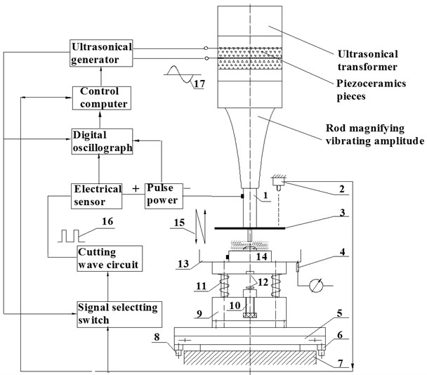
The pulse electrical micro-fine system compound synchronization ultrasonic vibration is built, it is shown in Fig. 1. Ultrasonic wave generator is a positive feedback amplifier that can track frequency automatically, it provides ultrasonic frequency signal to the energy transformer, the later changes electrical energy to mechanical energy, and generates ultrasonic frequency vibrating in piezoceramics pieces energy transformer end surface. The ultrasonic frequency can be adjusted from 16 KHz to 24 KHz, the ultrasonic frequency vibrating power can be adjusted from 0 W to 150 W continuously. The rod magnifying vibrating amplitude can enlarge the vibrating amplitude, and connects with the energy transformer by screw thread, micro-electrode connects with the screw hole of rod magnifying vibrating amplitude, and connected surface is full of plant oil for to decrease energy losses. The rod makes the electrode doing ultrasonic frequency vibrating, when machining starts, the frequency should be adjusted achieving resonance, the vibrating amplitude will get maximum value. The pulse power supply positive role connects with tool electrode; the negative role connects with the micro work piece. Definite micro-pressure remains between workpiece and cathode ensuring the cathode and micro-workpiece contacts with stable micro-pressure (0.30 N ~ 5.0 N).
Other units are labeling in Fig. 1: 1 – electrode, 2 – laser sensor, 3 – vibrating measuring benchmark chip, 4 – axis measuring meter, 5 – feed table, 6 – axis feed driver, 7 – base, 8 – axis feed driver, 9 – working table base, 10 – screw measuring meter, 11 – spring, 12 – magnetic pole, 13 – workbench, 14 – workpiece, 15 – ultrasonic vibrating, 16 – cutting signal, 17 – ultrasonic signal.
Fig. 1Synchronizing micro-fine machining system
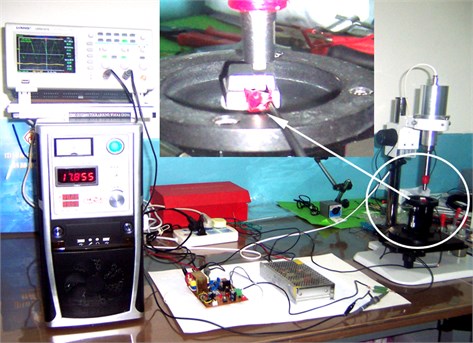
The ultrasonical vibrating combined synchronizing pulse electrochemical micro-machining system is shown in Fig. 2.
Fig. 2Picture of synchronizing micro-machining system
2.2. Synchronizing electrical circuit design
The ultrasonic combined micro-machining experiment system is shown in Fig. 3, the outer end line of ultrasonic electrical signal, the outer end line sends ultrasonic electrical signal for synchronizing modeling electric circuit.
The modeling circuit generates the cutting electric pulses, which turn on or turn off the power supply of electrochemical machining. Synchronizing way of turn on or off power supply is shown in Fig. 3(a). When the gap between workpiece and cathode become lesser than the given gap, turn on the power supply, the micro machining starts. When the gap between workpiece and cathode becomes bigger than the given value, turn off the power supply, the micro machining stops for to remove outcomes and to renew electrolyte. Synchronizing modeling electric circuit is shown in Fig. 3(b).
Fig. 3Principle of synchronization modeling circuit
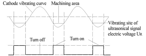
a) Synchronizing way of turn on or turn off power supply
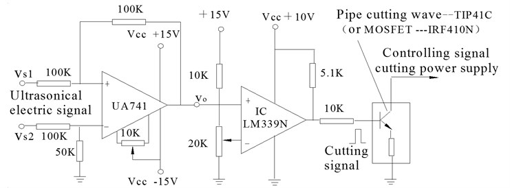
b) Synchronizing modeling electric circuit
2.3. Test of vibration system
The laser-CCD sensor for to measuring micro-displacement, device connecting is shown in Fig. 4(a).Test result is shown in Fig. 4(b).
The following is the result. The amplitude of vibration system prior to optimization is 0.0025 mm as is shown in Fig. 5(a). The amplitude of optimized system is 0.008 mm as is shown in Fig. 5(b) [9-10].
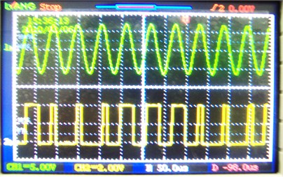
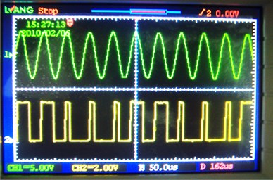
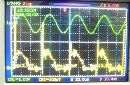
That circuit can turn on or turn off the power supply. As the signal synchronizing errors are little, and it can be also adjusted, the synchronization of the micro-machining electric pulse with ultrasonic vibrating may be realized. The synchronizing micro-fine pulses with ultrasonic signal waveforms measuring by the digital oscillograph are shown in Fig. 6(a).
Using laser-CCD sensor to measure ultrasonical vibrating signal, based the gap between tool and workpiece, turn on or turn off the pulse power, the ultrasonic electric signal and synchronizing pulse can be seen in Fig. 6(b), by contrasting the two waveforms, the good synchronising accuracy can be gotten using the cutting wave electrical circuit designed.
Fig. 4Test of vibration system
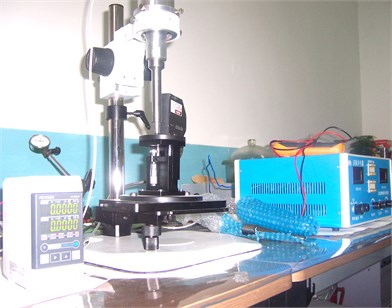
a) Device connecting
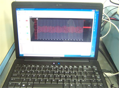
b) Display image of micro-displacement
Fig. 5Contrast of amplitudes of the vibration system
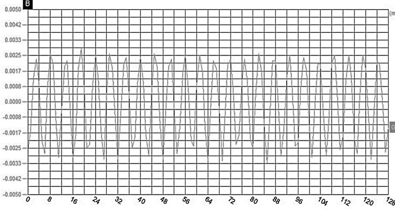
a) Amplitude of previous system
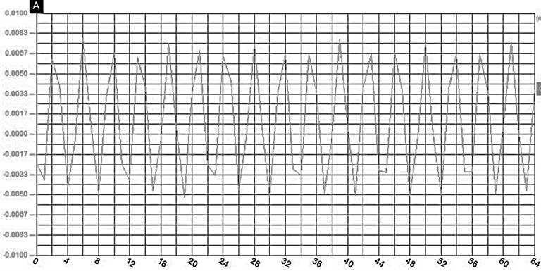
b) Amplitude of optimized system
Fig. 6Comparative study about ultrasonic electrical signal and synchronising pulse
a) Vibrating system
b) Laser sensor
3. Machining test of the micro-fine machining system
3.1. Micro-pits with square array
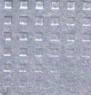
The electrolysis voltage amplitude 3 V, 5 % NaNO3 electrolyte aqueous solution, the static pressure 2.0 N, ultrasonic power 50 W B4C-W10 powder mixed, processing materials is hard alloy YG8, machining time is 2 min. The ultrasound a composite electrolytic square array photomicrograph micro-pits is shown in Fig. 7.
The phenomenon almost is elimiated about the square corner becomes round (as the electrolytic scattered corrosion) and side length becomes larger, reliable machining accuracy is ±1 μm.
Fig. 7Photos of the square array of micro-pits
a) 0 V (ultrasonic machining)
b) Direct electric current
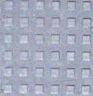
c) Pulse frequency 5000 Hz
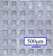
d) Synchronizing pulse
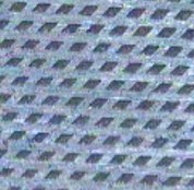
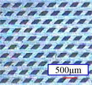
3.2. Micro-pits with diamond array
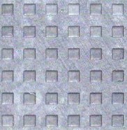
The electrolysis voltage amplitude is 3 V, 5 % NaNO3 electrolyte aqueous solution, the static pressure 2.0 N, ultrasonic power 50 W, B4C-W10 powder mixed, processing material is stainless steel S25, the processing time is 2 min. Ultrasonic composite electrolytic machining diamond array micro-pits, the photoes are shown in Fig. 8(a) – Fig. 8(d). By microscopic images, the synchronous composite machining can get better precision and surface quality.
Fig. 8Photos of the diamond-shaped array of micro-pits
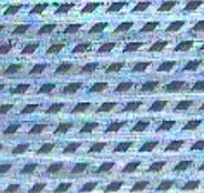
a) 0 V (ultrasonical machining)
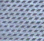
b) Direct electrical current
c) Pulse frequency 5000 Hz
d) Synchronizing pulse
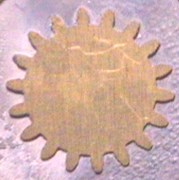
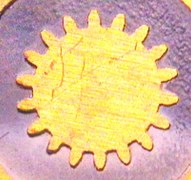
3.3. Micro gear
Electrolysis voltage amplitude are 2 V, 3 V, 4 V, 5 V, 2 % NaNO3 electrolyte aqueous solution, the static pressure is 2.0 N, ultrasonic power is 60 W, B4C-W10 powder mixed, processing material is hard alloy (YBD151), the processing time is 3 min.
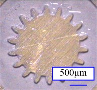
The micro gear machined by different voltage are shown in Figure 9. Figure 9, gear parameters: 18, 0.20 mm, forming precision is very good, with the machining voltage amplitude increases, the productivity increases (machining depth increases), but when the voltage is 5 V, the gear edge has a slight electrolytic stray corrosive effect [9-10].
It can be seen in Fig. 9, the voltage 4 V, the micro gear machining by ultrasonic synchronized electrolytic has both the effects of electrolysis and spark discharge, the reason is that electrolyte of 2 % NaNO3 aqueous solution has lower conductivity, and processing interpole generating ultrasonic cavitation, and the hydrogen bubbles, so that the electrolyte conductivity decreased further, the working fluid is the breakdown in specific location point, this will produce micro-spark discharge [11-12], the waveform, bubbles and micro-spark discharge shown in Fig. 10(a) and Fig. 10(b).
Fig. 9Different voltage ultrasonic composite synchronous processing of micro gear

a) 2 V
b) 3 V
c) 4 V
d) 5 V
Fig. 10Ultrasound synchronous processing micro gear (voltage is 4 V)
a) Current signal waveform diagram
b) Bubbles and micro-spark discharge
4. Conclusions
(1) The ultrasonical compound synchronizing micro-fine machining system can get good synchronising accuracy between ultrasonic vibrating and pulse power, and the ultrasonical compound electrical machining system works reliably, the corrrectness of the design of the cutting electrical circuit is proved.
(2) The possibility and the technology advantages are verified by the tests about ultrasonic compound electrical micro-fine machining, the combined technology has good machining precision and high productivity.
(3) Adopting the lower voltage, and the passivation electrolyte with the lower electrical conductivity, the better machining precision and the good surface quality, the lower cost can be acquired by the ultrasonic compound synchronizing micro-fine machining.
References
-
Wang Zhennong Micro Manufacturing Technology. National Defense Industry Press, Beijing, 2005.
-
Fan Zhejiang, Wang Tiancheng Electrochemical Machining Technology and Study Approaches. National Defense Industry Press, Beijing, 2005.
-
Rolf Schuster, Viola Kirchner Electrochemical micro machining. Science, Issue 289, 2000, p. 98-101.
-
B. Bhattacharyya, J. Munda Experimental investigation into electrochemical micromachining (EMM) Process. Journal of Materials Processing Technology, Issue 140, 2003, p. 287-291.
-
Zhao Wansheng, Wang Zhenlong Ultrasonic and electric discharge machining to deep small hole on titanialloy. Journal of Materials Processing Technology, Issue 120, 2002, p. 101-106.
-
Kock M., Kirchner V., Schuster R. Electrochemical micromachining with ultrashort voltage pulses – versatile method with lithographical precision. Electro-Chemical Acta, Issue 48, 2003, p. 3213-3219.
-
Kozak J., Rajurkar K. P., Makkar Y. Selected problems of micro electrochemical machining. Journal of Materials Processing Technology, Vol. 149, Issue 1-3, 2004, p. 426-431.
-
Zhu Yongwei, Wang Zhanhe, Yun Naizhang The micro-machining system and the test study of ECM combined ultrasonic vibrating. Mechanical Science and Technology for Aerospace Engineering, Vol. 27, Issue 3, 2008, p. 986-991.
-
Xinlei Miao, Yongwei Zhu Optimal design and test of ultrasonical vibration system. Applied Mechanics and Materials, Vol. 226, Issue 1, 2012, p. 21-25.
-
Zhu Yongwei, Wang Zhanhe, Li Hongying, Yun Naizhang The mechanism and test study on micro-machining of ECM combined ultrasonic vibrating. Chinese Mechanical Engineering, Vol. 19, Issue 17, 2008, p. 1786-1792.
-
Zhu Yongwei, Wang Zhanhe, Fan Zhongjun, et al. Ultrosonic combined electrical micro-machining technology and its application. Jixie Gongcheng Xuebao, Vol. 43, Issue 6, 2010, p. 186-197.
-
Ai Xing Study on high efficiency machining technology and its applications. Engineering Science, Vol. 2, Issue 11, 2000, p. 41-51.
About this article

China National Science Foundation (51075355), Jiangsu Province Science Foundation (BK2009194) support the paper study works. Authors give cordial thanks for the two funding organisations.
