Abstract
The article deals with the influence of the shot recoil of various weapons mounted on the armored vehicle HMMWV M1151 influencing the vehicle vibration when driving on uneven road surfaces. The solutions are given to ensure the safety of the crew when installing the non-standard weapon systems on the off-road vehicles.
1. Introduction
Tactical armoured vehicles are characteristic of a good protection of a crew and transportation of troops against small arms bullets and small calibre projectile fragments. They are widely used in contemporary military conflicts and international peacekeeping operations. Therefore a great attention is paid for their development and improvement in armed forcers of NATO countries [1].
A modern vehicle consists of a number of mechanisms and systems the functioning of which is interrelated. The principles of vehicle design and theoretical background of their operation are presented in the publications of T. K. Garrett, H. Heisler, J. Y. Wong and other researchers [2, 3, 4]. Modern vehicles and particularly military often are operated in difficult off-road conditions where dynamical parameters of suspension, wheels, road and other systems are of crucial importance for achieving the necessary performance parameters what is presented in the publications of R. N. Jazar, H. B. Pacejka, K. Popp, W. Schihlen and other researchers [5, 6, 7, 8]. Great influence on dynamical properties and stability of a military vehicle has the armament installed in it as during shots it plays the role of powerful excitation source [9, 10].
At the moment of firing, the gun shot creates vibrations that are transmitted to the combat vehicle corps. The carrier corps oscillation has a large influence on the security of the carrier movement; high amplitude of oscillation increases the drivers and crew fatigue, driving becomes dangerous. When firing with armoured mounted machine gun additional vibrations appear and having assessed the influence of these vibrations it would be possible to assess the driving safety with the machine gun firing in different directions and to make assumptions whether more powerful weapons can be mounted on the armoured vehicle.
The Lithuanian army use a number of HMMWV M1151 vehicles with mounted 12.7 heavy machine guns. The article will investigate the influence of armoured gun recoil on the dynamics of vertical vibrations of the armoured vehicle and possibilities to install on the HMMWV M1151 heavier weapons such as 14.5 mm heavy machine gun and the 20 mm cannon.
When firing from the 12.7 mm HMMWV M1151 heavy machine gun mounted on a vehicle, additional forces appear which also influence the vehicle chassis. This effect increases when driving on a rough road surfaces. Since the Lithuanian army plans to use these tactical armoured vehicles for a long period in future, it is important to have a possibility to mount more powerful weapons on these vehicles. When the maximum vertical displacements of the chassis are identified, conclusions can be drawn on the meaning fullness of modernization and its costs.
2. Recoil effect on the shooter
Recoil – weapon’s movement backwards at the moment of firing. A shot causes the sound, a weapon moves backwards and the shooter experiences a shock. Thus, recoil is a mechanical and psychological effect on the shooter. Recoil shock value largely depends on the shooter's physical parameters that are determined by the skeletal and muscular structure, and the handling conditions of a weapon [9]. When the weapon is mounted on a heavy armoured vehicle, recoil size largely depends on the fortification design and vehicle weight.
If a weapon and a bullet weights are the same, then, a weapon during the firing moves at the same speed as a bullet, but in the opposite direction. We can state that the heavier is a weapon, the smaller is the recoil and vice versa, the heavier is a bullet and the stronger is the powder power that gives higher initial velocity to the bullet, the stronger will be the recoil.
Fig. 1“Barrett” with a recoil measurement connected equipment
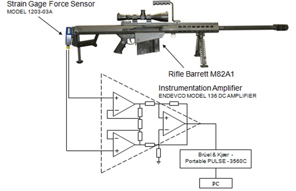
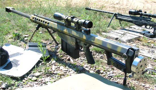
Fig. 2“Barrett” in the butts with the scheme
When a weapon is mounted on the armoured tactical vehicle, the vehicle weight is as if added to the weapon’s mass and a heavier weapon effect are observed. Higher weight resists the recoil therefore the recoil will be smaller. To the contrary, if there was no resisting mass, the recoil would be much greater.
Therefore, when the recoil is measured or calculated, the term “free recoil” should be defined, which a recoil velocity or energy caused by a weapon to which no additional weight is added, i.e. the influence of vehicle mass on the movement of a weapon is ignored. A weapon is as if hanging in the air and a shot is made. “Barrett” rifle recoil measurements were made when firing with 12.7 mm bullets.
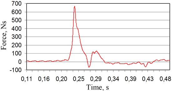
Fig. 3“Barrett” recoil measurement results
Instrumentation amplifier equipment was used to measure the recoil (Fig. 1, 2). The equipment was connected to the strain gage force sensor. Signal was stored by Brüel & Kjær portable Pulse 3600C software and displayed on a portable computer screen.
We see that the recoil reaches the peak value of 980 N and the force impulse is 15.07 Ns approximately, what does not cause any particular problems to the shooter (Fig. 3).
3. Recoil components and principles of its parameters’ identification
Weapon recoil is caused by three factors [9]:
• reaction accompanied by the bullet acceleration from the still position till the moment the bullet leaves the weapon at the so called muzzle velocity at a weapon muzzle;
• reaction accompanied by gunpowder charge acceleration up to a half of the muzzle velocity. When a bullet leaves a weapon, gunpowder gas fills the entire barrel and cartridge slot. Part of the gas moves together with a bullet at the same speed, the other part of the gas remains in the cartridge slot. Therefore, gunpowder gas average city in the barrel is calculated by dividing the speed of a bullet by two.
• reaction accompanied by the explosion of gunpowder gas going out of the weapon barrel when the bullet leaves the weapon and releases the gas, which thus causes a “rocket” effect.
The main recoil calculation principles are based on the principles of Newton's third and momentum conservation laws.
Having assessed the bullet movement in the barrel acceleration and the length of the gun barrel, it is possible to calculate the gas-generated gunpowder force :
here – mass of the bullet; – muzzle velocity at a weapon muzzle; – the gun barrel length. The expressions of this section are used to determine the absolute magnitudes of the recoil.
The recoil is composed of two parts: primary and secondary recoil. The primary recoil is caused by the force acting on a weapon. The same size only the opposite direction force is acting on a bullet. Based on the dynamics of linear momentum theorem:
– mass of the weapon, – velocity of the weapon recoil velocity.
When 853 m/s, 0.0428 kg, 14 kg (“Barrett” sniper rifle 12.7x99 mm is used):
The bullets kinetic energy is calculated as follows:
The recoil force influencing the weapon:
where – the barrel length ( 0.736 m).
The secondary recoil is reduced to the minimum having made the cuts at the barrel end. Outgoing gas is dissipated and it does not significantly influence the movement of a weapon at the moment of firing. Therefore, we will further analyze the weapon recoil, paying no attention to the effect of the gas.
We see that the theoretically calculated recoil significantly differs from the recoil measured with the device support. This shows the efficiency of the gas compensator, which creates good conditions for the shooter. We make a scheme of forces acting on HMMWV M1151 vehicle moving at the speed of 15 m/s and firing at the maximum rate of 2 seconds. We write down the differential equations of a weapon planar motion.
4. Development of the mathematical model and research of the planar motion of a vehicle with a weapon
4.1. Dynamic model of the HMMWV vehicle
Planar motion of a vehicle with a weapon at the moment of firing is analyzed considering the spring and damping characteristics of a vehicle. For that purpose dynamic and mathematical models of a vehicle at the moment of firing in planar were made. We consider a vehicle with a weapon as an entire body mass as the weapon is mounted on the heavy armoured vehicle.
Fig. 4Dynamic model of the M1151 HMMWV vehicle
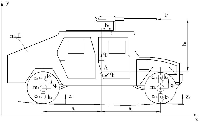
Planar movement of the vehicle is analysed. The gravity centre of the vehicle is point . The weapon and vehicle interaction in the model is simulated by the mechanical springs with rigid elements and dampers with viscous elements . Force initiating the weapon recoil was calculated in section 3. We write down the system’s kinetic energy [12]:
Potential energy of the system:
Suppressive function of the system:
We use second degree equation of Lagrange:
We write down the differential equations of the planar motion of the vehicle:
The force acting on the car is described according to the variable function:
where is the force acting on the car during the firing, – angular frequency, – time. This function shows that the recoil force of the firing with a machine gun mounted on the armoured vehicle is 600 rounds per minute.
Differential equations of the planar motion of the vehicle with the weapon were solved with the Maple mathematical package using the Runge-Kutta method. We assume that the initial displacements, velocities and accelerations are equal to 0. Data values used in differential equations and the main weapons parameters are given in Table 1 [13].
Table 1Weapons parameters
Round, mm | Bullet weight, kg | Muzzle velocity | Muzzle energy, J | Length of the barrel, m | Rate of fire, rds/min |
12.7x99 | 0.0429 | 887 | 16876 | 1.14 | 600 |
14.5x114 | 0.06344 | 976 | 30215 | 1.346 | 600 |
30x113 | 0.237 | 800 | 81000 | 1.55 | 720 |
4.2. Vehicle dynamics using 12.7 mm machine gun Browning 50
The calculation process and formatting of the results are carried out with Maple mathematical package.
When shooting with the machine gun Browning at the maximum speed, every shot occurs approximately every 0.1 s.
Displacements of the key elements of the vehicle chassis are illustrated in Fig. 5.
Fig. 5Displacements of the main chassis components of the vehicle HMMWV M1151 when firing with a 12.7 mm heavy machine gun Browning 50
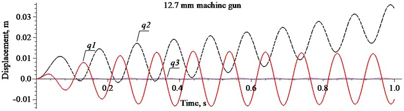
The obtained result shows that the recoil force influences the vehicle at its maximum force in a sinusoidal curve every 0.1 s, and the most dangerous situation for the vehicle occurs when driving on rough road and firing in the direction of movement as shown in Fig. 5, 6.
We see that the displacement of the centre of the vehicle at the moment of firing with a weapon of 12.7 mm calibre is about 0.02 m and its amplitude does not increase.
Fig. 6Oscillations of the mass centre of the carrier HMMWV M1151 when firing with the heavy machine gun Browning 50
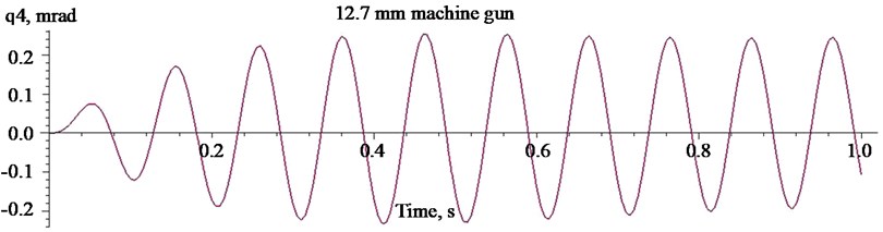
The carrier center variations in the picture are stable. We may conclude that the vehicle swinging when driving with the existing chassis over a rough road at the speed of 15 m/s and firing at the maximum rate of fire in the direction of movement can be considered not dangerous.
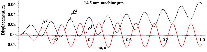
4.3. Vehicle dynamics using more powerful 14.5x114 mm and 30x113 mm weapon systems
Using the same parameters and the chassis of the vehicle and travelling at the same speed and on the same road, but firing with a large calibre machine gun, such as using KPVT using 14.5x108 mm ammunition, we get the chart of the displacement of the main chassis components.
Fig. 7 shows that after 4th shot the displacement of the chassis element sharply increases and firing in the direction of movement is complicated. It shows that the vehicle swinging after the fourth to fifth shot the system does not set back in place, which suggests the need for armoured vehicle to stop or stop firing.
Fig. 7Displacements of the main chassis components of the vehicle HMMWV M1151 when firing with a machine gun KPVT
Having mounted on the current carrier's chassis cannon firing 30x113 ammunition, we calculate displacement of the carrier's chassis key elements depending on the time shift under the same conditions but the shooting rate is 720 shots per minute.
When shooting with bullets 14.5x114, displacement becomes higher than 0.04 m after sixth shots, however, when shooting with a 30 mm cannon ammunition 30x113, after two shots (Fig. 7, 9).
Fig. 8Oscillations of the mass centre of the carrier HMMWV M1151 when firing with the heavy machine gun KPVT
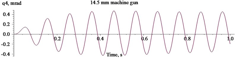
Fig. 9Displacements of the main chassis components of carrier HMMWV M1151 when shooting with 30 mm cannon
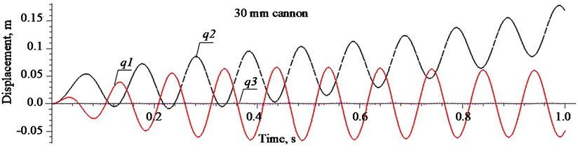
Fig. 10Oscillations of the mass centre of the carrier HMMWV M1151 when firing with the 30 mm cannon
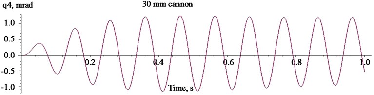
In the Fig. 10 the oscillations of the mass centre of the carrier HMMWV M1151 are presented. From the data presented in Figs. 6, 8, 10 it can be observed that amplitudes of angular oscillations of the vehicle chassis grow from 0.2 to 1 mrad in case of weapon’s calibre increase and correspond the tendencies of displacement change of other chassis elements.
5. Conclusions
Having performed the theoretical calculations and assessed the obtained results, we can judge that shooting while driving on an uneven road surface with standard 12.7x99 mm calibre cartridges has no significant effect on armoured tactical vehicle HMMWV M1151.
In order to be able to use the chassis of the off-road tactical carrier HMMWV M1151 in more powerful weapon systems, vehicle chassis – weapon systems modification is necessary.
In case of military emergency, having installed on the tactical carrier HMMWV M1151 chassis more powerful weapon systems it is absolutely necessary to strictly avoid shooting longer than 3 to 4 shots volleys.
References
-
Priegnitz J. Future armoured and non-armoured vehicles in the German army. Military Technology, Vol. 23, Issue 2, 1999, p. 43-49.
-
Garrett T. K., Newton K., Steeds W. The Motor Vehicle. 13th ed., Oxford, Elsevier Butterworth–Heinemann, 2001, p. 1188.
-
Heisler H. Advanced Vehicle Technology. 2nd ed., Oxford, Elsevier Butterworth–Heinemann, 2005, p. 664.
-
Womg J. Y. Theory of Ground Vehicles. John Wiley & Sons, Inc., Hoboken, New Jersy, 2008, p. 560.
-
Jazar R. N. Vehicle Dynamics: Theory and Application. Springer, 2008, p. 1015.
-
Pacejka Hans B. Tyre and Vehicle Dynamics (Second Edition). Published by Elsevier Ltd., Oxford, UK, 2006, p. 238-256.
-
Popp K., Schihlen W. Ground Vehicles Dynamics. Springer, 2010, p. 350.
-
Sapragonas J., Makaras R. Investigation of movement of the off-road vehicles under roadless conditions. Journal of Vibroengineering, Vol. 13, Issue 3, 2011, p. 334-341.
-
Szmit L., Wozniak R. Specificity of design and action of the weapon‘s jump and recoil laboratory test stand. Problems of Mechatronics (Armament, Aviation, Safety Engineering), Vol. 3, Issue 9, 2012, p. 29-39.
-
Droppa P., Stiavnicky M. Vibrations simulation of wheeld vehicles. Problems of Mechatronics (Armament, Aviation, Safety Engineering), Vol. 2, Issue 8, 2012, p. 17-28.
-
Lyman R. 48th Edition Reloading Handbook. Lyman Publishing Corporation – Connecticut, 2003, p. 480.
-
Bela L. Sandor Engineering Mechanics Statics and Dynamics. 2nd ed., Prentice Hall, Inc., Englewood Cliffs, N. J., 1987, p. 928.
-
Dapkevičius G. The Reference Book of the Foreign Countries Land Force. Military Academy of Lithuania, 1996, p. 197-216.
About this article

