Abstract
According to the characteristics of rotating synchronous fixed-length cutting system and the principle of vector coordinate transformation, it respectively analyzes the mathematical model of three loops which are the position loop, speed loop and current loop of the servo fixed-length cutting system in this paper. In view of the different working conditions of the system and its nonlinear problem, it puts forward that the function of the speed loop is realized by the parameter adaptive fuzzy algorithm; the function of the position loop using is realized by feed forward proportional control algorithm; the function of the current loop is realized by the conventional PI control algorithm. It uses MATLAB to make simulation and verification, the results show that the combined control algorithm can make that the fixed-length cutting system has characteristics of fast speed, high precision and strong robustness properties.
1. Introduction
The flying shears is one of the indispensable and crucial equipment in the continuous rolling production line, which cut the moving plate in accordance with the setting fixed-length. Especially with the increasing production and varieties of modern steel production, the development of high-speed and continuous mode of production, it puts forward higher requirements for the design and manufacturing quality of the flying shears, such as the characteristics of response sensitivity, accuracy of movement, stability and reliability. Therefore, it is one of the hotspots to improve the speed and performance of the flying shear [1-3].
Currently, the speed and position control of the flying shears is achieved by AC servo motor to achieve fast tracking and accurate positioning. AC servo system have the high requirements of the control strategy, the traditional control methods (such as the conventional PID controllers) can not satisfy the requirements. This is mainly due to the AC servo system exists time-varying parameters, uncertainties of load disturbance, the severe nonlinear characteristics of the AC motor itself and the controlled object and the Strong coupling factor. Therefore, the ideal control strategy requires not only meets the dynamic and static performance, but also should have the ability to inhibit various nonlinear factors impact the system, so that the system has the capacity of the decoupling and robustness.
In view of these factors for AC servo system, based on analyzing the characteristics, the process and the mathematical model of rotating synchronous fixed-length cutting system, the study on servo control Strategy of the fixed-length cutting system has the vital significance in this paper.
2. The process of the servo fixed-length cutting system
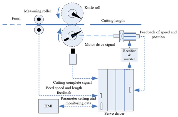
The structure of the servo fixed-length cutting system is shown in Figure 1, when the feed material goes by the measuring roller and the knife roller with a certain speed, the servo drive can obtain the length and speed of the feed material by the measuring roller, after control algorithm processing, the servo drive motor to rotate in order to drive the flying shear cut off the feed material when it reaches the preset set length.
Based on the feed continuity and the movement way of the knife roller, the servo fixed-length cutting system can be divided into three types [4-6], as shown in Table 1.
Table 1The types of the servo cutting in fixed-length
System | Feeding way | The motion type of the knife roller | The cutting way of the flying knife |
Go and stop mode | Intermittent feeding | Fixed | Static cutting |
Reciprocating mode | Fixed speed and continuous feeding | Linear return movement | Dynamic synchronous cutting |
Rotation mode | Fixed speed and continuous feeding | Rotating repetitive motion | Dynamic synchronous cutting |
Compared with the first kind of static cutting, the second and the third mode belong to the dynamic and synchronous cutting system. It requires that the horizontal linear velocity of the servo flying is same with the horizontal speed of the feed plate, so called it as “flying shear”. While the structure and the control method of rotary synchronous cutting system are the most complicated, it will be the focus of our research.
Fig. 1Servo cutting in fixed-length structure
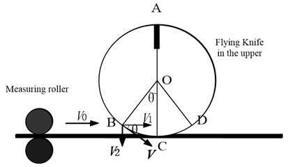
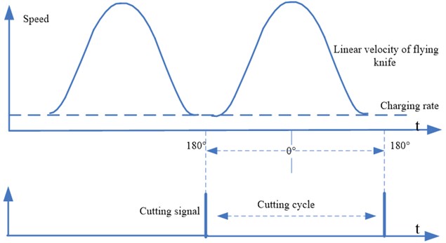
During the cutting cycle of a dynamic loop, the motion mode of the flying shear mechanism is divided into asynchronous period DAB part and synchronous period BCD part (as shown in Figure 2). In the synchronous period, the horizontal component value of the flying knife’s linear velocity and the horizontal speed of the feed material are maintained synchronization by control system, i.e., . Servo motor drags flying knife to rotate, when the blade arrives to the point C, the upper and lower cutting knife will cut off the plate. After the flying knife of flying shear mechanism arrives at the point D, system will enter into the asynchronous period.
Fig. 2A mathematical model analysis of the cutting knife
In the cutting cycle of a dynamic loop, the motion curve of the flying knife and the cutting length set by human-computer interface and the rotation circumference of the flying shear are related, is an important parameter in the system, the flying knife motion curve can be divided into 5 kinds of cases in accordance with the ratio. Specific as follows:
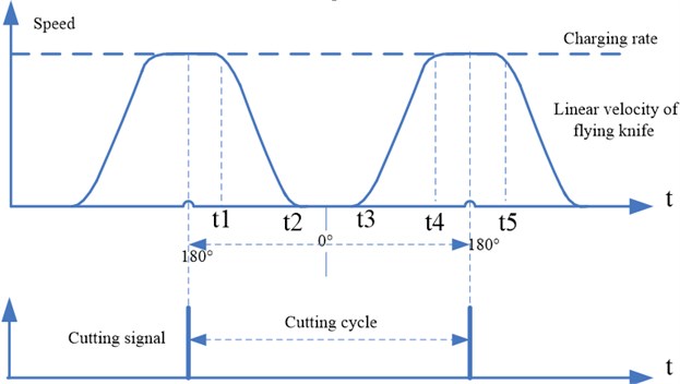
(1) :2. When the cutting length is two times greater than the circumference of the knife blade moving track, the motion state of the flying knife can be regarded as the following four states: synchronous period → deceleration process → stop motion → start acceleration → synchronous period (as shown in Figure 3). After all the setting parameters is completed, the servo fixed length cutting system starts to work and constantly collects the encoder signal of measuring roller to get the length and speed signal of the feed plate. Based on the control algorithm, servo motor drives fly cutter movement according to a given curve to obtain accurate motion trajectory. At the beginning with the tangency point of the first 180°, the horizontal component of flying knife’s linear velocity has been the same as the speed of the feed plate until the point D which is the end of the synchronization period. After the precise operation of the servo drive, the speed of flying knife drops to zero moment ,while the azimuth angle of the knife is just stops at 0°, and stops for a period of time. The ratio of is larger, the flying knife has more long stagnant time in the wave trough in order to prepare for the next cutting cycle.
Fig. 3Curve of the flying knife motion
(2) 2. When the cutting length of the material is equal to the circumference of the knife blade moving track two times, the curve of the flying knife motion is: synchronous situation → reduction process → zero state → acceleration process → synchronous situation. This is the special form of the first case, when the flying azimuth angle is zero, the instantaneous velocity of flying knife also drops to zero, but it don't stay here.
(3) 21. When the cutting length of the material is less than two times and greater than one time of the moving track circumference of the knife blade, the curve of the flying knife motion is: synchronous situation → reduction process → acceleration process → synchronous situation (as shown in Figure 4). Unlike the above two cases, the speed of the flying knife is reduced after the point D on the trajectory, but not reduced to zero, and thus there is no zero regions. Based on the accurate calculation and control of the servo driver, the speed of the flying knife drops to a certain value and then starts to accelerate, when the horizontal component of the flying linear speed reaches the speed of the feed plate, it just able to enter the synchronous period and maintain this state until the next cutting cycle.
(4) 1. When the cutting length of the material is equal to the circumference of the knife blade moving track, the curve of the flying knife motion is: flying blade does uniform circular motion in accordance with the speed of the feed plate.
(5) 1. When the cutting length of the setting plate is less than the circumference of the knife blade moving track one time, the curve of the flying knife motion is: synchronous situation → acceleration process → reduction process → synchronous situation (as shown in Figure 5). The flying knife immediately begins to accelerate while it is out of the synchronous period. Based on the accurate calculation and control of the servo driver, the speed of the flying knife accelerates to a certain value and then starts to drop, when the horizontal component of the flying linear speed reaches the speed of the feed plate, it just able to enter the synchronous period and maintain this state until the next cutting point. Note, if the ratio is too small will not only cause severe vibration of the servo motor, also cause great influence on the cutting precision.
Fig. 4Curve of the flying knife motion
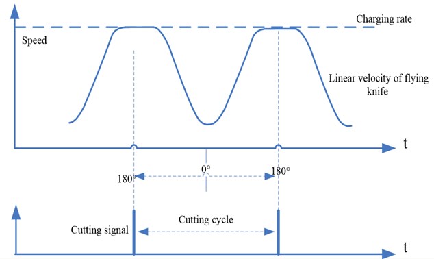
Fig. 5Curve of the flying knife motion
Based on the analysis, the operation speed of the servo system affects the production efficiency of the production line, the cutting accuracy and the quality of the products.
3. Control strategy of servo driver
The Fixed-Length Cutting System is a position control system. There are three loops in order from outside to inside which are the position loop, speed loop and current loop (as shown in Figure 6) [7].
3.1. Analysis of the current loop
The current loop is one of the three loops in servo system, which is mainly responsible for the regulating the excitation current and torque current after vector decoupling. In order to quickly and accurately control the torque of the induction motor and the motor internal excitation control, Two current loops’ controller output voltage quantity, through the corresponding transformation, the processor sends out six pulses to drive the six switches of IGBT in IPM based on the method of space vector pulse width modulation. Therefore, the controlled object also can be regarded as the synthesis which is consisted of intelligent power module and induction motor stator loop. According to its characteristics, the inverter can be processed as a first-order inertia link, the stator loop of induction motor can be regarded as a first-order inertia link constructed by the resistance and inductance, the current detection can be processed as a proportional link, and the filter also can be used as a first-order inertia link. The control model of the current loop can choose proportional integral model. The structure of the current loop is formed by the mathematical model of each link, such as shown in Figure 7 [10-12].
Fig. 6Structure diagram of servo three loops
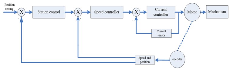
Fig. 7Current loop structure diagram
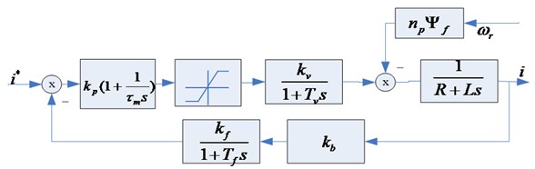
Without considering the influence of link of back electromotive force, the closed-loop transfer function of the current loop can be obtained from Figure 7:
In the formula: and are respectively proportional and integral coefficient of the controller, and are respectively the gain of the inverter and the time coefficient, and are respectively resistance and inductance values in the winding of induction motor stator, and are respectively the gain of the current filter and time factor, is the ratio coefficient of current detection link.
The current loop is not considered the impact of back electromotive force in the design, the current filter and inverter are processed as a small inertia, and ultimately, the transfer function about the current loop can be obtained as follows:
In the formula:
In the design of servo loop, eventually the current loop is treated as a part of the speed loop, the actual current filter and time constant of inverter link is smaller and the speed loop is generally considered to have a low cut-off frequency, thus, the current loop can be reduced order as:
From we can infer. If the requirements of the overshoot 5 %, the preferable damping ratio, , . By the above reasoning and bringing the actual data into the transfer function, we can obtain the values of the proportional and integral parameters of the current loop.
Through the principle of vector control discussed, we learned that the torque is proportional to the current component of the decoupled torque current. In order to improve the accuracy and rapidity of the torque control, it has a direct significance that we study the control strategy of the current loop.
P or PI control algorithm is often used in the controller, from the difference between P and PI, we could see that the latter PI algorithm can eliminate the static error and meet the accuracy and rapidity, so the PI control algorithm is frequently used in the current loop.
3.2. Analysis of the speed loop
The speed loop is the more important loop in servo control, which plays an essential role. Its importance is self-evident. From comprehensive analysis of the system structure, it is known that the current loop can be handled into an inertial link in the speed loops, the part of speed detection constructed by the encoder can be handled into the proportional link. The structure diagram of the speed loop is shown in Figure 8.
Fig. 8Speed loop structure diagram
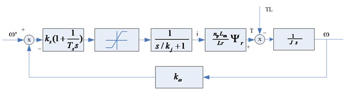
Open-loop transfer function is known from the above diagram:
In the formula: is the ratio of the torque and the decoupled current , and are the proportion and the time coefficient of the speed controller, is the proportion coefficient of speed sampling link, is the load inertia.
According to the open-loop transfer function of the speed loop, we design and calculate the related parameters based on the type II system:
is frequency width in the system.
At present, the speed loop of the servo system uses the proportional integral algorithm to adjust the speed. The each link of the speed loop elaborated in the front, which makes us have a clear and understanding algorithm to control the speed loop. However servo system is a nonlinear, more serious coupling system, especially for the speed loop, it contains the current loop. Thus, the parameters of the induction motor tuning is a higher technical requirement, for complex models of servo system, inappropriate Parameters severely affect the control effect of the speed loop and the whole accuracy and system stability. So further researching on control strategy about speed and self-tuning parameter in controller has an important practical significance.
The application of fuzzy control strategy makes testing and verification as follow, it provides reference and guidance for the practical application. In the general servo mechanism, the technician typically through a touch screen to set PID parameters and other parameters of the system. However, the conventional PID generally do not have the function of tuning , , parameters by the online, it can't effectively adjust PID parameters in different deviation case, so that it affects control effect to the system. Industrial field environment may be more complicated where has more electromagnetic interferences, sometimes the system itself has the nonlinear characteristics, it would be influenced by other factors, so that the system operating point may have a certain offset, the original set of parameters that are available may not necessarily suitable for the system. The result is that the system may produce errors.
If the application of look-up table based on fuzzy control strategy can adjust the PID parameters in real time, which will make the PID parameters keep at the right value. The following Figure 9 shows a fuzzy PID controller structure, its application is very extensive. We will further study its role in the servo speed loop.
Fig. 9Fuzzy PID controller structure diagram
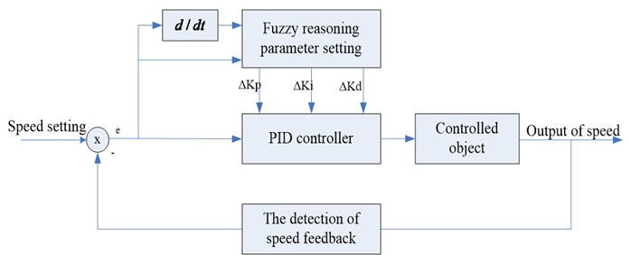
In this paper, the fuzzy PID controller structure is two dimensions of a single variable, the input deviation of the controller and the deviation change can fully reflect the dynamic characteristics of the controlled system. The effect of its control is better than one-dimensional controller, and the control structure is not three-dimensional complexity of the controller.
From the nature of fuzzy controller, it is the selection of input variables and output variables as well as the structure design of fuzzy controller. Fuzzy statement is constituted by the permutation and combination of different language value of input and output linguistic variables, which reflects a control method based on the artificial experience.
The vocabulary of the fuzzy language variables is an aggregate set by the grammar rules generated language value, therefore, the sub-file variable values for the language is more important, the more values, control rules is the more detailed, the control effect is better, but it undoubtedly is a major challenge for the actual control. If the partition is too simple, it will become very rough, more details were not taking into account that the control effect is difficult to meet the requirements.
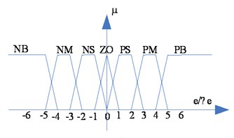
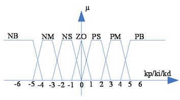
In the design of the automation engineering control, designers often make a compromise choice from the control complexity and control effect, the language variable usually has 2-10 values, in this case, seven values are chosen, which are NB (Negative Big), NM (Negative Median), NS (Negative Small), ZO (Zero), PS (Positive Small), PM (Positive Median), PB (Positive Big). In this case, the error, the error changes, and / / are quantized into 13 levels, which are expressed as {-6, 5, 4, 2, 1, 0, 1, 2, 3, 4, 5, 6}. The fuzzy language value and the number of language variable are as follows, and make a simple process:
{NB (Negative Big), NM (Negative Median), NS (Negative Small), ZO (Zero), PS (Positive Small), PM (Positive Median), PB (Positive Big)};
{NB (Negative Big), NM (Negative Median), NS (Negative Small), ZO (Zero), PS (Positive Small), PM (Positive Median), PB (Positive Big)};
{NB (Negative Big), NM (Negative Median), NS (Negative Small), ZO (Zero), PS (Positive Small), PM (Positive Median), PB (Positive Big)};
{NB (Negative Big), NM (Negative Median), NS (Negative Small), ZO (Zero), PS (Positive Small), PM (Positive Median), PB (Positive Big)};
{NB (Negative Big), NM (Negative Median), NS (Negative Small), ZO (Zero), PS (Positive Small), PM (Positive Median), PB (Positive Big)}.
After the input and output of the fuzzy controller is analyzed, the amplitude and width of membership function has great influence on the regulator's performance, we choose ladder and triangle because they are the simple mathematical formula with certain advantages, such as shown in Figure 10.
Fig. 10Linguistic variables of the input and output
a)
b)
Because the fuzzy control rule is a set of fuzzy conditional statements based on human experience, the fuzzy rules of the two-dimensional fuzzy controller are equivalent to a collection of a series of statements, as if: if and then , , and so on, shown in Table 2.
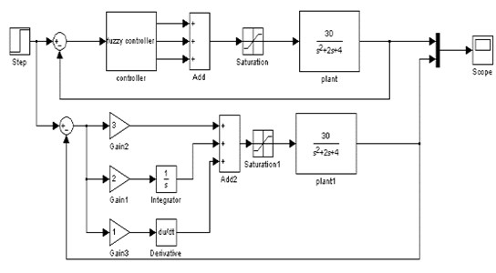
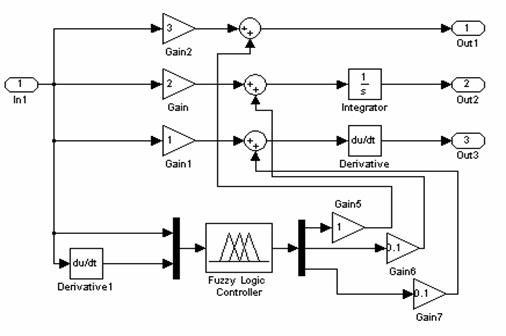
For this fuzzy controller, we have adopted the Mamdani inference method, and then the results are obtained by the MOM maximum membership degree method of fuzzy decision to get a clear quantity, all of which is easy to implement on the computer. By the above elaboration, the fuzzy strategy can be simulated by matlab/simulink, the structure chart of simulation and the controller subgraph are shown in Figure 11.
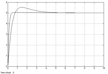
The simulation results are shown in Figure 12, it can be seen from the figure that the larger overshoot waveform is the waveform of the common PID, and the faster response, overshoot small waveform is a waveform obtained by the fuzzy PID controller. This shows that fuzzy PID has important significance to improve the control performance of the servo system.
Table 2Fuzzy rule table
NB | NM | NS | ZO | PS | PM | PB | |
NB | PB/NB/PS | PB/NB/NS | PM/NM/NB | PM/NM/NB | PS/NS/NB | ZO/ZO/NM | ZO/ZO/NS |
NM | PB/NB/PS | PB/NB/NS | PM/NM/NB | PS/NS/NM | PS/NS/NM | ZO/ZO/NS | NS/ZO/ZO |
NS | PM/NB/ZO | PM/NM/NS | PM/NS/NM | PS/NS/NM | ZO/ZO/NS | NS/PS/NS | NS/PS/ZO |
ZO | PM/NM/ZO | PM/NM/NS | PS/NS/ZS | ZO/ZO/NS | NS/PS/NS | NM/PM/NS | NM/PM/ZO |
PS | PS/NM/ZO | PS/NS/ZO | ZO/ZO/ZO | NS/PS/ZO | NS/PS/ZO | NM/NM/ZO | NM/PB/ZO |
PM | PS/ZO/PB | ZO/ZO/PM | NS/PS/PS | NM/PS/PS | NM/PM/PS | NM/PB/PS | NB/PB/PB |
PB | ZO/ZO/PB | ZO/ZO/PM | NM/PS/PM | NM/PM/PM | NM/PM/PS | NB/PB/PS | NB/PB/PB |
Fig. 11MATLAB simulation chart of speed loop
a)
b)
Fig. 12Simulation results of speed loop fuzzy algorithm
3.3. Analysis of the position loop
The position loop plays an important role in the servo control system. The deviation counter chip of the position loop at auxiliary shaft in the servo system processes the instruction pulse signal of PC or control card, in addition, it also counts the pulse signal gotten by position sensor’s (encoder) feedback, and then it is processed by adjusting deviation algorithm of position controller, the output drive servo motor to run. As a closed loop system, it completed the accurate positioning of position until the deviation disappearance or the allowable error in a certain range.
The servo system usually works in start, stop, acceleration, and deceleration of the repeat state, the servo driver requires a higher response speed of the system. In view of the fact that it has a higher requirement for the control system response speed, and the servo position control itself has a high request of the accuracy, therefore, appropriate and reliable processing algorithm is an important indicator to the reasonable position loop.
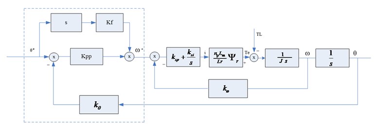
The driver based on the advanced control algorithm often helps to improve the performance of the control system, the proper feed-forward control can greatly improve the response speed of the instruction, and does not produce stability problems for servo system. Most of the speed feed-forward are provided by the motion controller, a speed command generated by the pulse command generator is multiplied by a factor, and then add the output of the position loop to form the speed command. The position loop is mainly proportional control and auxiliary feed-forward control to enhance the effect of the system's control. The structure diagram is shown in Figure 13 by the dashed box.
Fig. 13Position loop structure diagram
In accordance with the design requirements of the crossover frequency in the servo three loops, the crossover frequency of the current loop is more than 5 times the crossover frequency of the speed loop, the closed-loop transfer function of the current loop is treated as 1, the structure diagram of the position loop is to be dealt with accordingly.
If the ratio of the crossover frequency of the speed loop in the control system and the crossover frequency of the position loop is high enough, the closed-loop transfer function of the speed loop is also treated as 1, so we can get the closed loop transfer function of the position control system:
In the formula: is the feedback coefficient of the position loop, is the feedforward coefficient of the position loop. is the reciprocal of the crossover frequency of the position loop, so the feed-forward coefficient is a key parameter, it cannot be set too big.
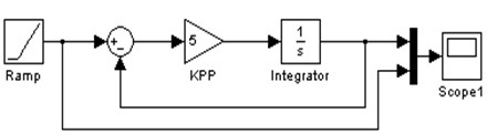
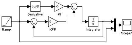
With the improvement of the accuracy requirements of the modern servo, the position loop also requires no overshoot and fast response. Only relying on P control algorithm, static error can not be eliminated, which is a fatal defect to the higher requirements system, so the P + feedforward control method can greatly reduce the static error. More importantly, the error remains within a certain range by debugging related parameters. The function of the position loop with feedforward link can be simulated by the MATLAB/SIMULINK in Figure 14.
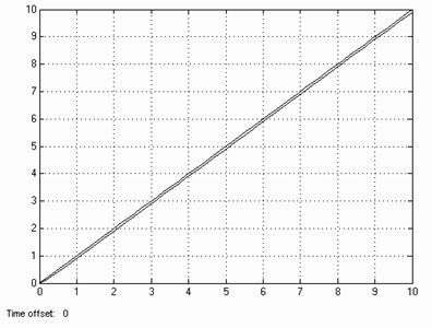
The simulation results without feed-forward link of the position loop is shown in Figure 15, compare with Figure 15 and Figure 16, the feed-forward of the position loop with high precision has a great significance.
Fig. 14Simulation diagram of position loop without feedforward and with feedforward
a)
b)
Fig. 15Tracking response of sloper of position loop without feedforward
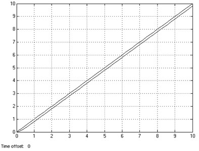
Fig. 16Tracking response of sloper of position loop with feedforward
4. The hardware structure of the driver
The hardware structure of the servo driver is ARM + FPGA. The combination of the ARM and FPGA forms the control module, which solves the defects of the conventional microprocessor to realize the motion control algorithm. FPGA builds the position loop, which simplifies the workload and the design difficulty of the peripheral digital logic circuit. FPGA constantly obtains the speed and length signal of the feed plate, and then, processes into a speed signal and passes to the ARM controller unit. ARM controller builds the speed loop and the current loop, ARM itself has the advantages of low cost, relatively mature design as the setting of the speed loop. Chip was integrated asynchronous serial interface, Ethernet interface, SPI interface, I2C BUS interface and CAN interface for easy networking and upgrading of the system. The hardware structure diagram of flying shear servo controller based on ARM and FPGA is shown in Figure 17.
Fig. 17The hardware circuit structure
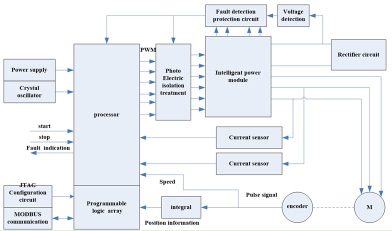
Fig. 18The actual flying shear cutting system
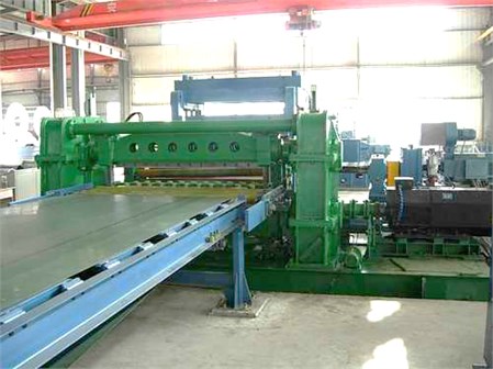
Based on the mathematical model of the induction motor, the principle of vector control and the hardware structure of the above, the control strategy has been successfully applied in the fixed-length cutting system. The actual flying shear cutting system is shown in Figure 18.
5. Conclusions
It analyzes the process of the rotating synchronous fixed-length cutting system in this article. According to the different ratio between the length of the cutting sheet and the rotation perimeter of flying shear, it analyzes 5 different motion curves of the flying shear, and puts forward the study on structure and control method of the rotating synchronous fixed-length cutting system. Through the establishment and analysis of mathematical models of the position loop, speed loop and current loop of fixed length cutting servo system, it is proposed that the fuzzy self-tuning PI algorithm is used in the speed loop, the feed-forward + Proportion algorithm is used in the position loop, conventional PI control algorithm is adopted in the current loop. Simulation of MATLAB software shows that the overshoot of the system is greatly reduced to improve the quality of the servo system. The driver uses a hardware configuration of the ARM + FPGA, by measuring the actual stator current waveform, it indicates a good control effect.
References
-
Grigaitis A., Gelezevicius V.-A. Development of electropneumatic servo system with reference model based signal adaptive force controller. Journal of Vibroengineering, 2007, Vol. 9, Issue 4, p. 45.
-
Grigaitis A. A flexure-based long-stroke fast tool servo for diamond turning. International Journal of Advanced Manufacturing Technology, 2012, Vol. 59, Issue 9-12, p. 859.
-
Bajodah A. H. Servo-constraint generalized inverse dynamics for robot manipulator control design. International Journal of Robotics & Automation, 2010, Vol. 25, Issue 1, p. 38.
-
Xudong Zhang Start-stop flying shear control system. Journal of Electric Drive, Vol. 36, Issue 11, 2006, p. 43-46.
-
Yonghu Zhang, Baining Chen The machine design and structure analysis of rotary flying shear. Journal of Mechanical Engineer, Vol. 32, Issue 1, 2008, p. 68-69.
-
Fahai Li, Yan Wang Motor and Drive Foundation. Qinghua University Press, Beijing, 2006.
-
Xu Liu, Yi Ruan A kind of the method about asynchronous motor rotational inertia identification. Journal of Motor Control and Application, Vol. 39, Issue 6, 2009, p. 1-3.
-
Kui Lin The analysis of 170 mm crosscut flying shear control system. Journal of Family Garden BBS, Vol. 160, Issue 1, 2005, p. 42-45.
-
Hui Xu, Lan Xiao Research on SVPWM inverter digital voltage regulation technology. Journal of Nanjing University of Aeronautics & Astronautics, Vol. 34, Issue 5, 2012, p. 456-458.
-
YuYao He Motion Control System. Xian University of Electronic Science and Technology Press, Xian, 2009, p. 305-308.
-
Xueming Zhang, Guohou Li Application of fuzzy control in the servo system. IEEE 2009 Chinese Control and Decision Conference (CCDC 2009), 2009, p. 1641-1644.
-
Cheng Ying, Hai Chen Qin Synchronized control of dual linear motors position servo system based on multi-axes motion control card. Journal of Advanced Materials Research, Vol. 433, 2012, p. 7152-7158.
-
Cao Rongmin, Zhou Huixing The linear motor control based on ELVIS. Proceedings of International Conference on Control and Decision Conference (CCDC), Taiyuan University of Science and Technology, China, 2012, p. 2505-2509.
About this article

