Abstract
This study measures the accuracy of two radio signal-based positioning methods to track targets in an indoor environment using radio frequency identification (RFID) and a wireless sensor network (WSN), the advantages and disadvantages of which are compared, analyzed, and discussed. We propose a specific configuration to perform measurements in a real environment using various positioning algorithms. The experimental results show that the number and the quality of the reference tags influence the accuracy of positioning when using RFID devices. Although WSN devices require fewer sensors, the unit price of sensors is comparatively high. In addition, adjusting the antenna angle achieves a stronger received signal strength indicator variation when using RFID devices. For WSN devices, the key is to avoid interference between sensors because it causes large errors when estimating the distance between 2 points. The proposed positioning methods are suitable for patrol systems, and can be employed to obtain security service personnel location data and confirm their patrol routes. This study adopts active RFID technology and nano real-time positioning WSN technology to test the indoor positioning accuracy of these technologies and related system construction issues. The findings provide a reference for future research on indoor positioning method selection.
1. Introduction
Global positioning systems (GPSs) have been widely adopted in outdoor positioning applications. However, a regional positioning system is necessary to achieve precise indoor positioning of the target. Indoor positioning data can be used to locate fixed or moving objects. Furthermore, the location of moving objects can be tracked to ensure that its coordinates are known after being moved.
Previous research on logistics management promoted the use of radio frequency identification (RFID) systems to locate indoor objects. During delivery, objects can be traced by recording data as they pass through transfer nodes [1]. A recent study employed wireless sensor network (WSN) nodes to collect environmental information such as the temperature [2]. WSNs have also been applied to wearable physiological monitoring systems. The radio wave feature of WSN devices also makes them suitable for research on indoor positioning [3].
Numerous indoor positioning system theories and methods have produced varying levels of accuracy. Accuracy is crucial because it influences the time required to trace an object [4]. Therefore, this study employs active RFID and a nano real-time accurate positioning WSN to test various positioning algorithms. The transmission frequency bands for both systems is set at 2.4 GHz. Based on preliminary results [5], this study examines the accuracy of these technologies when applied to an indoor positioning system, and analyzes the difficulties associated with developing such systems. This study employs the following two positioning system measurement methods: (a) time of arrival (TOA); and (b) received signal strength (RSS). The performance of these methods is compared based on the experimental results and the actual location of measured objects. The experimental results are discussed to examine the effectiveness of these methods for indoor positioning system applications, which serves as a reference for future studies on selecting appropriate indoor positioning methods.
2. Positioning sensors and applications
WSNs comprise a wireless network structure and sensor modules that transmit data via interconnected devices. These devices are capable of transmitting wireless signals because they have their own power source. The feasibility of implementing WSNs in areas where it is difficult to install wired devices can be improved. Examples include indoor environment sensors or personnel positioning systems [3], debris flow detection in mountainous areas [6], and the monitoring of bridge conditions [7]. Thus, WSNs are suitable for collecting data from remote or scattered locations via radio transmission.
ZigBee-based WSN systems adopt the IEEE802.15.4 protocol, and feature compact modules that are cost efficient with low power consumption. They transmit radio frequencies at 2.4 GHz, 868 MHz, and 915 MHz. The IEEE802.15.4a protocol supports TOA technology for wirelessly measuring distances [8], which reduces the time for measuring the distance between modules.
RFID technology identifies tags via radio transmission. An RFID module comprises a reader and a tag. These components communicate at various frequencies that determine the transmission distance, which in turn leads to various effects in application. The methods used for data exchange via RFID radio transmission include the electromagnetic induction method and the electric wave method.
Wireless positioning can be categorized into indoor or outdoor applications. Outdoor positioning is typically performed using a GPS device combined with mapping software packages for navigation or locating nearby recreational areas to provide location-based services (LBS). The most common positioning method is the receiving-end range positioning method, where positioning is relative to the immediate area of the GPS device [9]. By using this approach, a GPS device identifies the approximate location of a target tag based on a specific receiving frequency range, which can be modified or narrowed by adjusting the power or placement of the GPS antenna to confirm the location of an object. For example, an RFID tag can be fixed to a target object that is beyond visual range, such as the underside of a manhole cover on an asphalt road. High-frequency signals from the RFID tag penetrate the asphalt, and regional features can be useful for improving the regional positioning for locating the RFID beneath the asphalt [10].
3. Positioning algorithms
After obtaining distances between multiple endpoints and a target object, the following method can be adopted to estimate the location of the target by ensuring that the obtained positioning data match the actual distances between the target and the endpoints [11].
When there are three endpoints, the triangulation positioning method is typically adopted [12]. The principle is identical to the mentioned approach. The procedure for estimating the location of an object by obtaining three distances between three known locations and the object is detailed as follows.
Set , which are the distances to the endpoints, which can be obtained using Eq. (1):
By subtracting the first equation from the second and third equations in Eq. (1) and using the least squares method, we obtain:
The terms in Eq. (2) are subsequently transposed to obtain Eq. (3) as follows:
Before applying the triangulation positioning method, the TOA method must be applied to measure the distance between any pair of RFID devices [13]. Ensuring the consistency of paired devices is the key. Two approaches are currently employed to ensure consistent readings between any two RFID devices, which are crucial when applying the TOA method. The two-way ranging method is used to calculate the distance by timing the signal transmissions between two unsynchronized transmitters, whereas the one-way ranging method is used to obtain the distance by timing the transmission signals sent from one device to another.
This study adopts an IEEE802.15.4a ZigBee device to calculate the transmission time using the symmetric double-sided two-way ranging (SDS-TWR) method [14]. The SDS-TWR method transmits signals to measure the distance from the endpoints, and subsequently transmits signals to measure the distance from the receiving end. To reduce research costs, certain studies have applied the asymmetric double-sided two-way ranging (ADS-TWR) method to measure distance. For this method, a signal is sent to Node B immediately after Node A receives ACK1, thereby reducing the latency for REFRAM2 [15].
The difference between the transmission times of both endpoints is used to calculate the distance between them. Based on the principle that the difference between the distances from any point on a hyperbola and Foci A and B are fixed, a simultaneous equation can be obtained. This principle can also be applied to obtain the simultaneous equation for Foci A and C. Finally, the solution of these equations can be used to calculate the coordinates of a tracking tag [16].
Previous research has also used the angle of arrival (AOA) method to estimate the position of an object. The AOA can be calculated using an antenna matrix comprising two antennas that independently obtain the angle of incidence of a signal. The intersection of these angles can subsequently be used to estimate a target’s location [17].
A received signal strength indicator (RSSI) represents the transmission strength of a received signal [18], and is suitable for measuring the distance between two points. After a receiver is implemented, with a positioning tag, according to the planned routs on a map, signal strengths at all the points with fixed intervals are recorded in a database. Subsequently, a signal strength index map can be constructed. When a positioning device is activated, the closest signal strength on the index map can be used to locate a target based on the measured signal strength.
The LANDMARC positioning method is based on RSSI values. This method employs 16 reference tags, eight positioning tags, and four RFID readers. The signal strengths of the tags employed in this study can be categorized from Levels 1 to 8. If Tag is a tag to be positioned, then the positioning strength vector of Tag is expressed as , where is the number of readers, and is the signal strength received by Reader , where . If Tag is the reference tag, the positioning strength vector of Tag is , where is the strength of Tag received by Reader . Equation (4) shows that the relationship between Tag and Tag can be obtained. If the value of is small, Tag is proximal to Tag :
After obtaining the values from Eq. (4), they are ranked in ascending order. Starting from the smallest value, neighbors of the tracking tag are selected, , and Eq. (5) is subsequently applied to obtain the target object’s coordinates:
where is the weight of the th neighbor, as shown in Eq. (6):
Error can be obtained by Eq. (7) by using the positioning coordinates and the actual coordinates:
The Virtual Reference Elimination (VIRE) method [19] uses an algorithm derived from the LANDMARC method. There are more tag strength levels, and the concept of virtual tags, reducing signal interference on systems from tags. The interpolation method is employed to configure virtual tags based on the physical reference points on both sides. Signal values are calculated using the interpolation method according to numbers of virtual tags to be generated. In practice, the amplitude attenuation of equipment must be significant and stable enough to avoid large errors caused by generated virtual tags.
Based on this discussion, when applying AOA, it is necessary to employ specific equipment to obtain the directions of signals, which is difficult to source. For the TOA and TDOA methods, specific equipment is necessary to measure the transmission speeds. However, in the aspect of calculation, the triangulation method is simpler than the hyperbola method. Therefore, this study adopts two techniques. In Experiment 1, we use WSN ZigBee devices to measure the distance between points by applying the TOA method, and the coordinates are obtained using the triangulation method. Consequently, the influence of unstable SSR signals on distance measurements is avoided. For Experiment 2, we apply an RSSI to measure the strength of active RFID transmissions by adopting the original LANDMARC structure model. The RSSI values are compared against the reference points to improve the accuracy of the obtained positioning information.
4. Research design and experimental environment
This section presents a comparison of the construction processes and positioning effects of the discussed WSN and RFID systems. The indoor positioning systems were constructed based on specific assumptions regarding the experimental environments discussed in this section. Following the actual measurements, the signals from both systems were analyzed using various statistical tools. The errors in these experiments are the absolute errors of measured values and their corresponding actual values.
The equipment for the active system research comprised a 2.45G active RFID device (SYRIC) and four readers that were connected to a server via an Ethernet connection. Because the server had only one RS232 port, this study employed wired connections to the server through an Ethernet adapter through a hub. The RFID tags used were SYTAG245-2C active sheet tags with two battery cells and a 125M maximum reading range.
The active RFID signal experiment was conducted in an indoor environment with a length greater than 10 m. The active RFID equipment was employed to obtain the relationships between the measured distances and RSSI values, and the ZigBee equipment was used to record the errors between measured and actual distances. The measurements were taken at 1-min intervals. For the active RFID positioning experiment, we installed the four readers in the field tests, and we placed the active reference tags on the ground. Based on the recorded signal strengths, signal strength data were collected in advance to calculate the average signal strength, thereby ensuring signal stability. For models of reference tags at various distances, the reference tag closest to the tracking tag was identified. For different numbers of neighbors (3, 4, and 5 in this experiment), eight tracking points were identified. We subsequently applied the LANDMARC method to measure the points to be positioned.
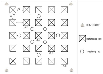
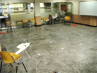
(1) For the experiments, we adopted the LANDMARC method for positioning the tracking object. When calculating the coordinates, we applied weights as multipliers. Consequently, the coordinates of the first tag at the top left of Fig. 1(a) is (1, 1). For subsequent experiments, we positioned the reference tags at various distances.
(2) In Experiment 1, the reference tags were positioned at 1-m intervals, which is the LANDMARC default distance between devices. Figure 1(a) shows the verification of the applied LANDMARC algorithm.
(3) In Experiment 2, we positioned the reference tags at 2-m intervals, and examined the changes in data as the intervals were increased (Fig. 1(b)).
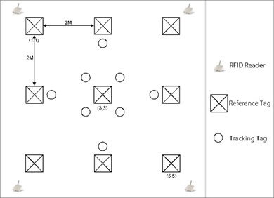
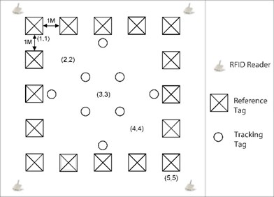
(4) In Experiment 3, the reference tags were placed along the perimeter at 1-m intervals. The influence of this arrangement on the accuracy is shown in Fig. 2(a).
Fig. 1Configuration of active RFID tags with: a) 1 m interval and the actual implementation, b) 2 m interval and the actual implementation
a)
b)
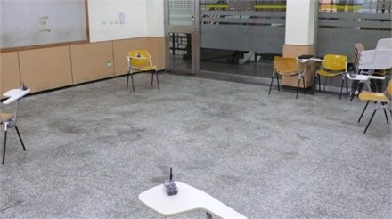
For the WSN system, we employed an HBE-Ubi-nanoLOC transmitter (HANDBACK) operating at 2.4 GHz, and adopted IEEE802.15.4a communication standards. The programming languages for Atmega128L were TinyOS and NesC. We employed the SDS-TWR method to measure the distances between devices. The signal distance experiment for ZigBee was conducted in the same environment as the RFID system experiment. For the ZigBee positioning measure, we installed three ZigBee reference devices, and employed an additional ZigBee device as the tracked target (Fig. 2(b)). Based on the measured transmission speeds, we selected five points for calculating the distances between the target object and other devices. These distances were subsequently applied to obtain the positioning data by using the least squares method with coordinate data.
Fig. 2Configuration of: a) active RFID tags with surrounding tags, b) ZigBee positioning test
a)
b)
5. Experimental results and analysis
This study performed three experiments with positioning equipment. The first experiment was conducted to estimate the signal distances and examine the influence of distance on accuracy. The second and the third experiments were positioning experiments that applied positioning models for the active RFID system and the Zigbee system within actual environments for measurement.
For the signal distance experiment with RFID tracking, we measured the signal strengths between the active RFID tags and readers at various distances ranging from 1 to 10 m. A minimum of five measurements were taken at 1-m intervals. For the ZigBee tracking system, we employed two ZigBee devices. The distances were calculated based on the actual distances from the transmitter and the corresponding arrival time of the transmitted signal. The measurements were performed at distances ranging from 1 to 10 m, with at least 20 measurements taken at 1-m intervals. The results for both experiments were recorded for subsequent analysis.
The positioning experiment was conducted in Classroom 619 in the Ta Yi building of the university. The size of the classroom was 10.0 × 7.5 m. We arranged a 4 × 4 m space in the center of the classroom as the environment for the positioning experiment.
The RFID positioning experiment was conducted with three positioning models. Measurements were performed at eight specific locations inside the measurement range. Five positioning measurements were performed at each tracking point, and eight measurements were taken at all reference points, except for those with low-strength signals. The purpose of this design was to examine how the number of references tags and neighbors influenced the positioning accuracy (Fig. 3(a)).
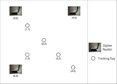
For the ZigBee positioning experiment, three positioning devices were established at Point 1 (0, 0), Point 2 (4, 0), and Point 3 (0, 4) (Fig. 3(b)). Five tracking points were selected within this space for subsequent measurement, and calculation of distances between the tracking points and the devices. Next, the least squares method was applied to calculate the positioning information. The results were recorded for analysis.
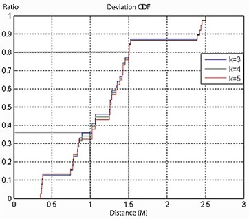
To measure the accuracy of the active RFID system, we first calculated the mean of the recorded signal strength data. Next, the LANDMARC algorithm was applied to calculate the errors corresponding to the evaluation models. The experimental results for the 1-m tag intervals are shown in Fig. 4(a). The errors at most 35 % of points were less than 1.0 m, and 50 % between 1.0 and 1.5 m. Regarding the choice of neighbors, the average error was the smallest, with the number of neighbors being five.
Fig. 3Field test for: a) active RFID positioning experiment, b) ZigBee positioning experiment
a)
b)
Fig. 4a) CDF with tags of 1 m interval, b) ZigBee positioning experiment
a)
b)
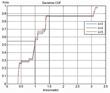
Figure 4(b) shows the experimental results of the tags placed at 2-m intervals. The errors for approximately 55 % of the points were less than 1 m, and 30 % ranged between 1.0 and 1.5 m. For neighbor selection, the average error was the smallest with five neighbors. However, the minimum error in this experiment was the largest among the three experiments.
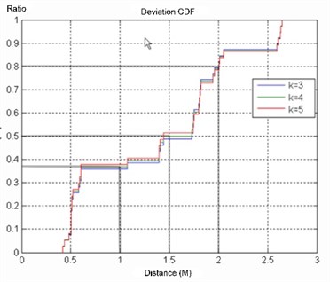
For the experiment with the surrounding tags placed at 1-m intervals, Fig. 5(a) shows that the errors for approximately 37 % of points were less than 1 m, 13 % were between 1.0 and 1.5 m, and 30 % were between 1.5 and 2.0 m. Regarding neighbor selection, the average error was the smallest with five neighbors. Furthermore, the minimum error was the smallest among the three experiments.
According to the comparisons of these experiments, the accuracy of Experiment 2 is higher than that of Experiment 1 or 3, primarily because there were fewer tags in Experiment 2, which reduced the errors from selecting points caused by RSSI abnormal surge waves. Furthermore, the circling block in Experiment 2 was better than that of Experiment 3. Although the experiment accuracy in Experiment 2 was superior, the maximum error in Experiment 2 was the largest among all the experiments.
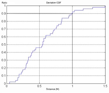
The experiment with the ZigBee system was conducted in a 4 × 4 m environment. The distance measurement formula was used with the least squares method to obtain the data of the tracking points. The data obtained are shown in Fig. 5(b), which indicates that almost 90 % of errors were less than 1 m, although the error fir Point 2-2 was greater than 1 m. This static positioning value was measured in a laboratory with the environmental consumption of a plane with no shelters. However, the maximum error at (4, 4) was 3 m. In this experiment, the distance between the tracking tag to (0, 0) changed from 6 to 7 m, leading to overlarge positioning errors.
Fig. 5a) CDF with surrounding tags of 1 m interval, b) CDF for ZigBee positioning errors
a)
b)
6. Discussion
For this study, we adopted and analyzed the accuracy of two radio signal-based positioning methods using RFID and WSN systems in an identical environment. The various characteristics and construction of these systems provide a reference for the construction of similar systems. The key points regarding cost, convenience, antenna orientation, and device stability are discussed as follows.
When constructing indoor environments for positioning using LANDMARC, the number and quality of tags obtained the largest variation in accuracy in this study, which has a direct effect on cost. Before an ideal set of standards is realized, the mass production of active tags is highly unlikely. Therefore, the most crucial factor is the environment size. If a system is implemented in a large environment, the range of the readers would be larger, and readers would be cheaper. Conversely, if positioning is performed in smaller environments, the primary influence on higher system costs would be on the four readers.
Regarding the WSN equipment, all devices are independent and interchangeable, thereby improving convenience. In addition, the IEEE802.15.4a standards were developed for the equipment used in this study. The equipment employed in this study was still only used in the laboratory with a higher unit price. Based on the current prices, adding only one tracking device would have significantly increased the costs of the overall system. However, if devices based on this configuration are mass produced in the future, the system cost could be reduced substantially.
Comparing the convenience of using active RFID and WSN devices for indoor positioning systems, we found that WSN systems are more advantageous than RFID systems. When configuring the LANDMARC tags employed in these experiments, it was necessary to measure the locations of the reference points in advance. First, we marked the coordinates (1, 1) in the environment, and subsequently placed reference tags at 1-m intervals. Furthermore, it was necessary to consider the tags’ transmission ranges, the angles of antennas, and the locations of tags to ensure that the readers received signals from all the tags.
Regarding the WSN system configuration employed in this study, we identified the coordinates of three points in the environment, and placed the ZigBee devices at those points. Intercommunication between devices was achieved via radio signals, and each device had its own power supply. It was unnecessary to consider power connection issues when configuring the devices. However, the battery life of RFID devices is approximately 1 to 4 years. Therefore, we recommend supplying power to the three points establishing such systems to ensure the practicability of the product.
Our experiments also showed that the orientation of RFID antennas influences the accuracy of the positioning measurements. The active RFID devices employed in this study featured a linear antenna; consequently, the signal range was influenced by the direction of the device. Therefore, the measurable distances might vary. For example, along the front direction, the read range was 80 m. However, the ranges on both sides were smaller. Therefore, we recommend the selection of devices with a relatively uniform read range for signal transmission. In addition, the range of the ZigBee device was large. In the corridor, the measured read range was 20 m.
Regarding the device stability, we observed that the angles of the active RFID tag antennas caused large variations in RSSI. Thus, in this environment, if the antennas were arranged at a horizontal angle, or if the angle of a reader antenna was altered, the corresponding RSSI value would differ. Furthermore, the LANDMARC system positioning was based on the received RSSI values. Therefore, the quality of the equipment influences the accuracy of positioning. And movements of tags would cause RSSI value deviations. Thus, the reference tags in this experiment were stationary. Moving tags would cause problems with neighboring tags. If future LANDMARC systems are implemented for dynamic positioning, further consideration must be given on equipment stability to promote dynamic positioning systems.
The WSN system in this study used TOA devices, and time was a key factor in calculating the distance. Within the scope of line-of-sight equipment, the distance between two points could be measured precisely. However, if any interference occurs between points, the error of the measurement of the distance between them would increase, leading to larger errors in calculation of intersecting points. Thus, we recommend installing this equipment under a ceiling and placing transmitters on higher platforms to avoid interference, such as that caused by mobile working stations or robot platforms. In addition, this equipment can be installed on helmets or backpacks of staffs for positioning. For example, it can be installed on steel helmets and backpacks of an army inside a tunnel to identify soldier locations.
7. Conclusion
After we applied and compared the two positioning mechanisms, we learned substantially on how experimental data could be influenced by changes in radio waves in the air. This is a crucial factor that requires careful consideration to improve the accuracy of positioning. In the experiment with the LANDMARC system, we learned the importance of RSSI stability. Therefore, we recommend simulating RSSI changes based on measured data, a novel positioning algorithm, or a unique approach to arrange reference tags, to verify the accuracy of positioning. Alternatively, future positioning studies can apply additional RSSI positioning models. Regarding the calculations during the LANDMARC experiment, although the accuracy of the obtained information is potentially poor, the errors can be applied in other fields. For example, they can be applied to a patrol system to retrieve the location information of security service personnel and confirm their patrol routes.
In addition, as the stability of WSN systems improves, dynamic positioning systems may be applied to retrieve information of the real-time locations of personnel or objects, and record their routes. Another application is the smart rescue robot platform. Existing GPS signals can be combined with indoor signals to improve the management of valuables. Another application is the smart house. This equipment can be combined with other sensor components to return information regarding the temperature, humidity, and light around an equipment. Alternatively, a physiological sensor mechanism can be integrated with the positioning sensors to provide more information on target personnel that require location based services.
References
-
C. Saygin, B. Natarajan RFID-based baggage-handling system design. Sensor Review, Vol. 30, 2010, p. 324-335.
-
A. Leo, G. Rinaldi, I. Stiharu, R. Bhat Wireless sensing using acoustic signals for measurement of dynamic pressure and temperature in harsh environment. Sensor Review, Vol. 32, 2012, p. 142-148.
-
B. Aygun, V. C. Gungor Wireless sensor networks for structure health monitoring: recent advances and future research directions. Sensor Review, Vol. 31, 2011, p. 261-276.
-
J. Golby Advances in inductive position sensor technology. Sensor Review, Vol. 30, 2010, p. 142-147.
-
T.-C. Liu A Comparison of Indoor Positioning Using RFID and ZigBee. Master Thesis, Department of Information Management, Chinese Culture University, Taipei, 2010.
-
B. E. Bilgin, V. C. Gungor Adaptive error control in wireless sensor networks under harsh smart grid environments. Sensor Review, Vol. 32, 2012, p. 203-211.
-
K. Sukun, S. Pakzad, D. Culler, J. Demmel, G. Fenves, S. Glaser, M. Turon Health monitoring of civil infrastructures using wireless sensor networks. 6th International Conference on Information Processing in Sensor Networks, IPSN 2007, 2007, p. 254-263.
-
J.-E. Kim, J. Kang, D. Kim, Y. Ko, J. Kim IEEE 802.15.4a CSS-based localization system for wireless sensor networks. IEEE Internatonal Conference on Mobile Adhoc and Sensor Systems, MASS 2007, 2007, p. 1-3.
-
F. J. Gonzalez-Castano, J. Garcia-Reinoso Bluetooth location networks. Global Telecommunications Conference, GLOBECOM '02, IEEE, Vol. 1, 2002, p. 233-237.
-
A. Y. Chang, C.-S. Yu, S.-C. Lin, Y.-Y. Chang, P.-C. Ho Search, identification and positioning of the underground manhole with RFID ground tag. Fifth International Joint Conference on INC, IMS and IDC, Seoul, Korea, 2009.
-
K. Pahlavan, L. Xinrong, J. P. Makela Indoor geolocation science and technology. Communications Magazine, IEEE, Vol. 40, 2002, p. 112-118.
-
K. Kyung, S. Kim, Lee J. H., H. Myoung, M. Kim Accuracy verification of optical tracking system for the maxillary displacement estimation by using of triangulation. J. Korean Assoc. Maxillofac. Plast. Reconstr. Surg., Vol. 34, Issue 1, 2012, p. 41-52.
-
J. Fang, A. Lim, Q. Yang TOA ranging using real time application interface (RTAI). In IEEE 802.11 Networks Green Communications and Networking, Springer, Berlin, Heidelberg, Vol. 51, 2012, p. 88-98.
-
O. Daegun, K. Myung-Kyun, C. Jong-Wha Subspace-based propagation delay estimation robust to frequency offset for two-way ranging. Communications Letters, IEEE, Vol. 16, 2012, p. 216-219.
-
H.-S. Ahn, H. Hur, W.-S. Choi One-way ranging technique for CSS-based indoor localization. 6th IEEE International Conference on Industrial Informatics, INDIN 2008, 2008, p. 1513-1518.
-
K. Woo Chan, S. Taek Lyul, D. Musicki Mobile emitter geolocation and tracking using correlated time difference of arrival measurements. 15th International Conference on Information Fusion (FUSION), 2012, p. 700-706.
-
K. Maruyama, H. Kameda A data association algorithm for specific radio source using angle difference of arrival. Proceedings of SICE Annual Conference (SICE), 2012, p. 713-718.
-
X. Yang, W. Pan, Y. Zhang A positioning algorithm for node of WSN based on received signal strength advances in multimedia. Software Engineering and Computing, Springer, Berlin, Heidelberg, Vol. 128, 2012, p. 441-446.
-
Y. Zhao, Y. Liu, L. M. Ni VIRE: active RFID-based localization using virtual reference elimination. International Conference on Parallel Processing, ICPP 2007, 2007, p. 56-56.
About this article

