Abstract
This paper concerns the main landing gear of certain light aircraft, and the dynamic stress on the main landing gear during the landing process is analyzed. A complete dynamic drop test is developed for the landing gear of light aircraft on the main landing gear, and the changes of dynamic strain exerted on the strut in the process of drop are measured. Simultaneously, the simulation software LMS Virtual.Lab Motion is used to build the rigid-flexible coupling dynamic model and simulate the process of drop and the results of the dynamic stress is obtained by means of computer simulation. Afterwards, the results of the dynamic stress between simulation and test are contrasted, and the sources of data error are analyzed. To sum up, the study shows that the dynamic stress in the flexible part of landing gear possesses a high accuracy through combining the analysis results of simulation and test, which meets the safety design criteria of the landing gear. Moreover, the method used to build the rigid-flexible coupling model is an available and reliable way for the simulation of drop test, which can provide a deep basis for future research.
1. Introduction
The landing gear of aircraft bears large impact loads during the landing process, and the internal structure of the landing gear emerges high dynamic stress. Thus it is very important to study the dynamic stress response of landing gear in the process of landing. Nowadays, the research on drop test is the main method for airworthiness verification. It can be used not only to check overload, brace, buffer distance, but also verify whether the landing gear achieves the design requirements of the desired strength and stiffness when the landing gear absorbs the impact energy. With the rapid development of aviation industry, the aircraft landing gear drop test technology has received wide attention, and several key technologies have been broken through. The dynamic analysis and drop tests for specific aircraft landing gear have been extensively studied by scholars from various countries at different viewpoints.
In 1997, J. C. Underwood described the final system drop test of the Disk-Gap-Band parachute system. The system consisted of three Disk-Gap-Band parachutes of different designs, each of which was optimized for its own task within the mission [1, 3]. In 1999, X. Wang from University Hamburg simulated the operation of Airbus A320 as an example and set up the main landing gear model. The highly nonlinear aircraft dynamics coupled with varying landing and runway conditions were handled web with the proposed fuzzy controller [4]. In 2000, Ghiringhelli from Politecnico di Milano used a two freedom model to investigate the simulation of semi-active control landing gear test with different subsidence velocity [5]. In 2004, Ghiringhelli used a multi-body dynamics software ADAMS to set up a complete model without considering about flexibility of airframe, and the PID controller was designed and improved to carry out simulation research on the semi-active landing gear control [6]. In 2004, Douglas summarized the testing and analysis used to quantify the expected airbag landing loads for the Mars Exploration Rovers. The airbag drop test setup, landing instrumentation, and the test data reduction method was discussed in order to provide an understanding of the empirical loads. A favorable comparison was made between the empirical data and available computational airbag models boosting confidence in the results [7]. In 2006, R. Lernbeiss and M. Plöchl introduced a MBS-based landing gear model, and investigated numerical simulation of a simple static and dynamic load by comparing with finite element model [8]. In 2009, J. P. Kong conducted drop impact analyses for SUAV's landing gear using the explicit finite element code LS-DYNA®. And experimental data were used to revise the impact model for the landing gear [9]. What’s more, structural particularity and airworthiness specifications should be considered in the landing gear drop test of light aircraft. For the light aircraft landing gear drop test technology, a test and control system had been introduced by Xue in 2011 [10].
Whereas, most of the scholars only considered the simulation, they lacked the test verification and comparative analysis. What's more, most of them regarded the structure of the landing gear as rigid body in the simulation, so they could not study the dynamic stress of the flexible structure during landing process. To meet the research requirements of the dynamic performance of light aircraft landing gear, the drop dynamic test of landing gear is conducted which not only analyzes the dynamic strength, but also provide the data for the analysis of the fatigue life. And we make the landing gear strut flexible and promote a rigid-flexible coupling dynamics in simulation by taking advantages of multi-body dynamic software LMS Virtual.Lab Motion. Not only the buffer performance of the landing gear is analyzed, but also the results of the dynamic stress in the key parts of strut are obtained by the improved method. It is necessary to study the dynamic strength of the landing gear. By comparing the results of the simulation and test, the results have quite a high accuracy. Evidently, the research possesses high academic values and engineering application values. Meanwhile, the analysis results afford reliable guarantee for the safety of the landing gear.
2. Dynamic drop test of landing gear
2.1. Dynamic drop test system
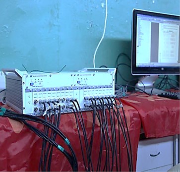
As the loading conditions of key parts on the landing gear are serious during the landing process, we must measure the dynamic strain on these key parts in the drop test. The dynamic drop test is conducted in the test system which is independently developed by Nanjing University of Aeronautics and Astronautics. The test system consists of the platform system, the low friction sliding system, the up and down system, the wheel's turning speed system, the impact platform system, the fixture system and the acquisition system. The test system uses the approach of reducing weight and falling freely from a specified height above the ground. The aircraft landing weight, angle of attack, sinking velocity, forward velocity, wing aerodynamic force and ratio of the friction between wheel and runway can be simulated at the moment of touchdown [1]. The drop test rig and the data collection device are shown in Fig. 1 and Fig. 2.
The expected results of the dynamic drop test on main landing gear of light amphibian aircraft include:
(1) Obtainment of the max dynamic strain results of landing gear parts (strut, rotating and shaft rocker arm) in the process of drop;
(2) Study on the force that the landing gear exerting on the road in different sinking speed and heading speed;
(3) Research on the relation of dynamic strain and the dynamic load that the platform exerts on the wheel, as well as the relation of maximalapp:addword:maximal load and minimalapp:addword:maximal strain. In addition, the phase of load and strain should be observed.
The strain of landing gear is caused by the impacting load in the dynamic drop test, which belongs to dynamic strain. The measurement accuracy of the dynamic strain is affected by the sampling frequency, dynamic response of strain gauges. Thus the following aspects should be considered in the measurement:
(1) System test frequency;
(2) Dynamic response and fatigue life of strain gauges;
(3) Anti-interference practice adopted in the measurement of dynamic strain.
Fig. 1Dynamic drop test rig for landing gear
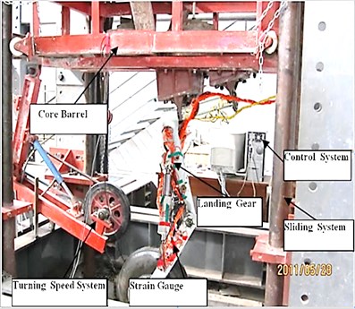
Fig. 2Data collection device for the test
In order to measure the dynamic stress correctly, the selection of strain measurement points must meet the following requirements:
(1) Superb reflection of the mechanical characteristics of the structure;
(2) Representation of the parts that bear the most serious load;
(3) Abilities to monitor structural damage conditions.
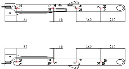
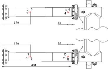
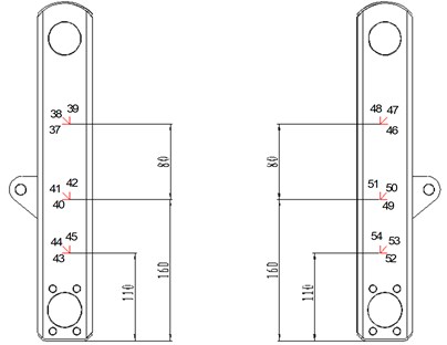
Based on the above selection criteria, the dynamic stress test points are arranged in key parts of the landing gear's shaft, pillar and rocker, which are shown in Fig. 3 (a-c). The initial parameters of the dynamic drop test are shown in Table 1.
Fig. 3a) gauges on the strut, b) gauges on the rotating shaft, c) gauges on the rocker arm
a)
b)
c)
Table 1Initial parameters of the dynamic drop test
Drop height /mm | Effective drop weight /kg | Diameter of main oil hole /mm | Diameter of one-way oil hole /mm | Initial pressure /MPa | Rolling speed /min |
410 | 329.8 | 2.6 | 1.8 | 0.6 | 1300 |
2.2. Test result of the dynamic drop test
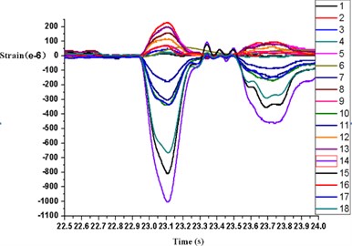
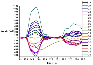
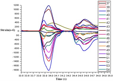
The desired results are obtained in the drop test. The time history responses of dynamic stain on parts of landing gear structure at different dropping height are obtained. Fig. 4 (a-c) shows the time history responses of dynamic strain at different strain measurement points in the drop process.
The test results show that a rebound off phenomenon exists on the landing gear when it is touching down, and the peak of dynamic strain increases with the increasing of the drop height. What's more, the vertical load holds a high-frequency oscillation phenomenon due to the operation of the wheel's turning speed system, while the dynamic strain of the landing gear structure are free of it. The dynamic strain of landing gear structure is less affected by the horizontal load than the vertical load.
Fig. 4a) gauges from number 1 to 18, b) gauges from number 19 to 36, c) gauges from number 37 to 54
a)
b)
c)
3. Rigid-flexible coupling dynamics simulation of landing gear
3.1. Rigid-flexible model
The model of landing gear needs to be simplified in the simulation software. In the case of not affecting the simulation accuracy, landing gear will be simplified for seven parts: landing gear strut, upper rod, lower rod, buffer bushing, piston-rod of buffer, rocker arm and the wheel. As the landing gear is connected with fuselage, we need to create a simple fuselage model, and the fuselage is used to connect with the landing gear, define the dropping weight, dropping direction and dropping height. In the fuselage model, we need to create three coordinates to replace three joints that are used to connect the landing gear. And another coordinate is created on fuselage which is used to define the dropping direction and the dropping height. Then, we build an entire model in one of the coordinates created above, and define the material properties for the entire model. By modifying the weight of entity model in LMS Virtual.Lab Motion software, we complete the definition of dropping weight.
After simplifying landing gear model and creating fuselage model, we need to define kinematic pair, road, parameter of buffer and tire, and set initial condition (dropping weight, dropping direction, dropping height and pre-speed of tire) in the LMS Virtual.Lab Motion software. Here, the process of retracting doesn't need to be considered unless in the process of drop. Except for a revolute joint that needs to constraint upper and lower rods, it is necessary that another cylindrical joint should be applied to them to constrain the rotational degree of freedom, so that the two rods will be locked. In addition, the buffer is defined by importing the formula and the empirical parameters, and the tire is defined as the nonlinear damping spring. Thus a rigid dynamics model is established, then it is saved as a Rigid. CATAnalysis file.
This article considers the landing gear strut as a flexible body, so we import CAD model of the landing gear strut into the finite element pre-processor software Patran, then divide the finite element grid and define material and element properties. It is quite necessary to create independent nodes in kinematic pairs. Otherwise, the connection between the flexible body and the other rigid bodies will fail. And then the Flex .bdf file is exported. The following processing procedures are as follows:
(1) Open Flexible Body Design module in the LMS Virtual.Lab Motion software. Then import the Flex. bdf file created above, and complete the creation of flexible body analysis file–Flex.CATAnalysis, this file is used to replace the rigid strut in the later step.
(2) Open the rigid dynamics model–Rigid.CATAnalysis file, then select the rigid strut in all the bodies in the model tree, choose Make Flexile With Existing Data, there will pop up a window, in the window we select the flexible body analysis file–Flex.CATAnalysis created just now. So the rigid strut is replaced by flexible body. Here the independent nodes created in the Patran are associated by the software automatically.
(3) Create the Rigid-Spider prepared for calculating the Craig-Bampton modal of the strut. The Rigid-Spider is similar to the multi-point constraints in the finite element method.
(4) Build a Nastran Craig-Bampton Case for creating a solving file for the finite element software Msc Nastran. According to the Flex.dat file modal frequencies will be calculated by Nastran. For the case the first nine modal frequencies are enough. And the modal frequencies are shown in Table 2.
(5) Import the Craig-Bampton modals that are calculated by Nastran into Nastran Craig-Bampton Solution. Then create a new Mode Set1, and choose Nastran Craig-Bampton Solution as its data. The damping ratio is 5 % in the strut.
Table 2Modal frequency of strut
Mode | 1 | 2 | 3 | 4 | 5 | 6 | 7 | 8 | 9 |
Frequency | 255.9 | 439.5 | 585.4 | 817.2 | 876.7 | 880.2 | 1140.7 | 1294.8 | 1420.1 |
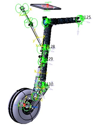
In the interface of Mechanism Design, Mode Set 1 created in last step is selected as Solution Set, and the solving type is set as dynamics. Last, set solving tolerance. Then, we finish building the rigid-flexible coupling dynamic model. It is shown in Fig. 5. In the figure, we can see that the rigid strut has been replaced with a flexible body.
Fig. 5Rigid-flexible coupling dynamic model
3.2. Dynamic simulation of landing gear
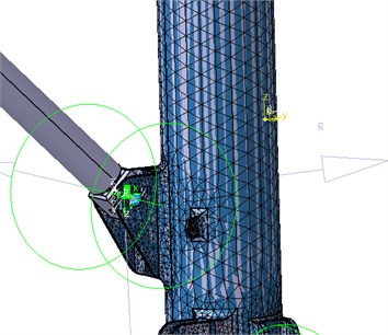
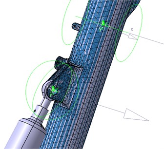
The focus of this paper is to study the dynamic stress of the landing gear in the process of drop, and analyze the dynamic stress response of the flexible strut. Here, we mainly analyze the dynamic stress in two dangerous parts of the flexible strut. One part is the joint that the piston-rod of buffer is connected to strut, and the other one is the joint that the lower rod is connected to the strut.The two parts transfer a large load relatively, which will cause stress concentration easily, and the load is complex. The structures are relatively weak, and they are damaged easily. Therefore, these two parts are selected to study their dynamic stress. And these two parts are shown in Fig. 6(a, b).
Fig. 6a) part including lower rod, b) part including piston-rod of buffer
a)
b)
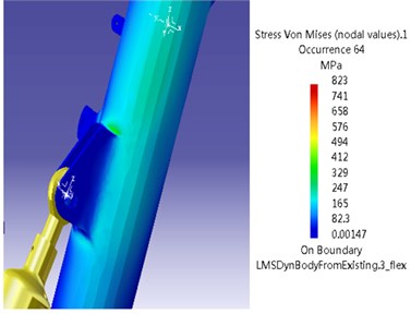
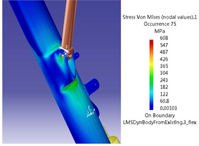
The models are calculated in the software LMS Virtual.Lab Motion, and we obtain the results. In the software, the dynamic stress is extracted. Then the dynamic strength is analyzed. The max dynamic stress nephograms of the two parts are shown in Fig. 7(a-b).
According to the nephograms above, the max dynamic stress of the strut beside lower rod is 608 MPa. And the material of strut is 30CrMnSiNi2A, the ultimate strength 1600 MPa. So the safety factor is 2.63, which meets the requirement of the dynamic strength. Besides, the max dynamic stress of the strut beside piston-rod of buffer is 823 MPa, the safety factor is 1.9, it also meets the requirement of the dynamic strength.
Fig. 7a) stress beside the lower rod, b) stress beside the piston-rod of buffer
a)
b)
3.3. Contrast analysis between the simulation and test results
In order to verify the the correctness of simulation model and accuracy of test data, the contrast of the dynamic stress between simulation and test is needed. In the test, the serials number of the gauge on the piston-rod of buffer and the lower rod connected to strut are listed in Table 3-4, and so is the max dynamic stress which is converted by calculation of the strain.
Table 3Stress distribution beside lower rod
Number of gauges | 19 | 20 | 21 | 31 | 32 | 33 |
Max dynamic stress (MPa) | 402.5 | 497.3 | 530.7 | 423.8 | 509.4 | 542.4 |
Table 4Stress distribution beside piston-rod of buffer
Number of gauges | 16 | 17 | 18 | 28 | 29 | 30 |
Max dynamic stress (MPa) | 567.2 | 687.6 | 751.3 | 594.7 | 645.2 | 743.1 |
According to the Table 3 and Table 4, the dynamic stress distribution of simulation is consistent with test generally, but there is a little error. The error of the max dynamic stress on the two parts is shown in Table 5.
Table 5Error analysis
Max stress beside piston-rod of buffer (MPa) | Max stress beside lower rod (MPa) | |
Simulation | 823 | 608 |
Test | 751.3 | 542.4 |
Relative error (%) | 9.54 | 12.09 |
The error of the simulation and experimental results is inevitable, and the reasons is listed below, which will benefit for future work:
(1) The dynamic model is simplified from the real landing gear, and the simplification would bring some error to the results;
(2) The quality of the finite element mesh of the flexible strut and several similar problems will affect the accuracy to a certain extent;
(3) The friction coefficient defined between the tire and the road can not be exactly the same with the real situation, which will have an influence on the simulation results;
(4) When defining the pre-revolution speed of the tire in the simulation, the tire has remained the same speed before the landing gear lands. But in the test, after the tire separates from wheel turn, the speed of tire will decrease gradually before landed due to all kinds of friction, which will lead to quite a smaller speed of the tire than the real condition.
4. Conclusions
Studies are carried out on the dynamic stress in the main landing gear of a light aircraft. A complete dynamic drop test has been developed which obtains the dynamic stress of key parts in the landing gear. Meanwhile, the rigid-flexible coupling dynamic model of the main landing gear has been built for light aircraft, and a dynamic simulation has been conducted in the LMS Virtual.Lab Motion software, and the dynamic stress has been gotten. Comparison has been made between the simulation results and experimental data. And the errors between them are analyzed. The results show that the dynamic stress of flexible part of landing gear possesses a higher accuracy through combining the analysis results of simulation and test, which meets the safety design criteria of the main landing gear. Simultaneously, the analysis results show that the dynamic stress distribution of simulation is consistent with test generally. Both of the maximum dynamic stress error can be controlled at around 10 %. That is to say, the method used to build the rigid-flexible coupling model is verified, which has provided a reliable and exact method about the dynamic stress simulation for the landing gear.
References
-
Daniels J. N. A Method for Landing Gear Modeling and Simulation with Experimental Validation. NASA CR 201601, 1996.
-
Horta L. G., Daugherty R. H., Martinson V. J., Veloria J. Martinson Modeling and Validation of a Navy A6-Intruder Actively Controlled Landing Gear System. NASA TP 1999-209124, 1999.
-
Underwood M. A. A system drop test of the Huygens probe. 14th AIAA Aerodynamic Decelerator Systems Technology Conference, San Francisco, AIAA Paper 1997-1429, June 1997.
-
Wang X., Carl Udo C. Fuzzy control of aircraft semi-active landing gear system. 37th Aerospace Sciences Meeting and Exhibit, Reno, NV, AIAA Paper 1999-265, Jan. 1999.
-
Ghiringhelli G. L. Testing of semi-active landing gear control for a general aviation aircraft. Journal of Aircraft, Vol. 37, No. 4, 2000, p. 606-615.
-
Ghiringhelli G. L., Gualdi S. Evaluation of a landing gear semi-active control system for complete aircraft landing. Aerotecnica Missili e Spazio, Vol. 83, No. 1, 2004, p. 21-31.
-
Adams D. S. Mars exploration rover airbag landing loads testing and analysis. 45th AIAA/ASME/ASCE/AHS/ASC Structures, Structural Dynamics and Materials Conference, Palm Springs, CA, AIAA Paper 2004-1795, April 2004.
-
Lernbeiss R., Plöchl M. Simulation model of an aircraft landing gear considering elastic properties of the shock absorber. Proceedings of the Institution of Mechanical Engineering, Part K, Journal of Multi-Body Dynamics, 221, No. 1, 2007, p. 78-86.
-
Kong J. P., Lee Y. S., Han J. D., Ahn O. S. Drop impact analysis of smart unmanned aerial vehicle (SUAV) landing gear and comparison with experimental data. Materialwissenschaft und Werkstofftechnik, Vol. 40, No. 3, 2009, p. 192-197.
-
Xue C.-J., Qi W.-G., Nie H. Test and control system development and application of a landing gear drop test rig. Transactions of Nanjing University of Aeronautics & Astronautics, Vol. 28, 2011, p. 145-151.
-
Xue C.-J., Han Y., Qi W.-G., Dai J.-H. Landing-gear drop-test rig development and application for light airplanes. Journal of Aircraft, Vol. 49, No. 6, 2012, p. 2064-2076.
About this article

This work is supported by Jiangsu Provincial Natural Science Foundation of China (No. BK2012795), Operating Expenses of Basic Scientific Research Project (No. NS2012081) and Priority Academic Program Development of Jiangsu Higher Education Institutions.
