Abstract
Nowadays, there are many diagnostic methods in medicine. A negative effect in implantology has been recognized since the 1980s. In general terms, if an implant is introduced into the body, it is sometimes not accepted by the organism. This effect is usually referred to as low level of implant stability. There are many reasons why such an effect takes place. This paper is focused on the mechanical point of view. There is a relation between mechanical movement of an implant and success of the surgery [1, 2]. Cervical implant was chosen for our research because there is no information about the stability thereof. Such knowledge can benefit surgeons. A device based on measuring response function was designed. This device is connected to an implant. The implant and its surrounding bone are the boundary conditions. It was expected that these boundary conditions can affect frequency response function in a connected structure. A beam with exactly defined mechanical properties was designed for cervical implant. A vibration head was attached to one end of the beam. The vibration head produces transversal vibration. An accelerometer to measure the response was attached to the other end. The vibration head utilizes a piezo actuator and inertia force. This device was tested in vitro on a cervical cadaver in a laboratory. Mechanical stability of the implant was simulated with axial force. The results were obtained in a frequency domain by Fourier transform. The focus is on resonance frequencies and resonance amplitudes. They show that there is a correlation between implant stability and response function evaluation. Further, a numerical model of the device designed was made. The model was built using the finite element method. Finally, the experimental and numerical models were compared.
1. Introduction
Measuring implant stability still constitutes a crucial issue. Many important factors can be measured in the human body implementing very sophisticated medical technologies. Nevertheless, very little is known of what happens when an implant is introduced into the body. It is well known that there are a lot of cases of implant failure. The reasons why this happens are not exactly known though. There are factors that affect success of the surgery. Generally, we divide these factors into two groups. Group one comprises biological factors while group two consists of mechanical factors. The biological factors include healthiness, smoking, diseases (for example osteoporosis) etc. Mechanical factors could be the following: density of the bone, stress and strain distribution in the bone. These factors strongly affect the primary and secondary implant stabilities. Simply put, the primary stability is affected by the mechanical factors while the secondary stability is affected by the biological factors. The primary stability can be described as a value that specifies how well an implant is placed in the bone. If there is a movement between the bone and the implant, you may assume that the primary stability is low. The secondary stability describes the interaction between the implant and the surrounding bone in time. The two stabilities relate to each other closely. The secondary stability depends on the primary stability. It is understood that implant stability affects success of the surgery. The method of detecting the stability utilizing a resonance frequency analysis is widely accepted in dental implantology [4, 6, 7].
The objective of this contribution is to measure the primary stability of an intervertebral cage expressed as a frequency spectrum of the vertebral system and intervertebral cage. The hypothesis is that the primary stability is affected by boundary conditions of the structure connected to the implant, especially the axial pre-stress. To our knowledge, no research has been carried out with respect to this issue yet.
2. Material and method
Two models were used to detect the primary stability: an experimental approach and a numerical model. The numerical model was built to estimate the dynamic properties of the detecting system proposed. The experimental model provided a process to evaluate the numerical model results.
The numerical model was built as a three dimensional model (Figure 1). We implemented the finite element method using a commercial package, MSC.MARC (MSC software s.r.o.). The model consists of two cervical vertebrae, an intervertebral cage, a connecting beam and an L shaped bracket with an actuator. The modal analysis and harmonic analysis with pre-stress varying from 0 to 100 N were performed. The range of frequencies between 0 and 5,000 Hz was researched.
Fig. 1Discretized model
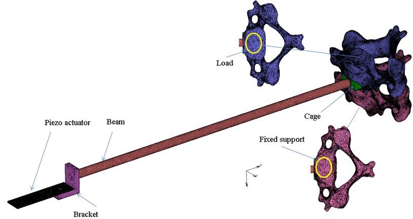
The simplified material model, which was used, is isotropic for all parts defined with the two engineering constants (Table 1). Zero displacement in all directions to all nodes of the C4 lower surface is prescribed. The pre-stress is prescribed to the upper surface of the C3 body. The glue contact is defined between all parts. A simple damping factor of the value 0.01 for all parts was specified.
Table 1Material properties of numerical model
Young modulus [MPa] | Poisson ratio [−] | Density [kg/m3] | |
Piezo actuator | 52,000 | 0.31 | 7,800 |
Bracket | 96,000 | 0.3 | 4,620 |
Beam | 96,000 | 0.3 | 4,620 |
Cage | 104,000 | 0.3 | 4,000 |
C3, C3 | 5,000 | 0.3 | 2,000 |
Experimental model is shown in Figure 2. The experiments were performed in a laboratory environment in vitro. An intact cadaver of a C3-C4 vertebrae segment from a 74-year-old male was used for the measuring. A hole was drilled into the cadaver and, consequently, an intervertebral cage (Implaspin Lasak s.r.o.) was implanted. Finally, the measuring device was connected to the cadaver with a beam. The measuring device is consisted of the parts shown in Figure 1. The vibration head was attached to an end of the bracket. The vibration head comprises a piezo actuator. The actuator rests on the L shaped bracket. It generated transversal vibrations based on the inertia force. Its driver was built for this experiment. An accelerometer to acquire the response was located on the top surface of the L shaped bracket. A personal computer was used to generate and acquire the data using software capable of generating any type of signal and, simultaneously, transferring the response to the frequency domain through a fast Fourier transform algorithm.
Fig. 2Experimental model
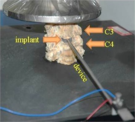
The primary stability is expected to rise with axial pre-stress. The implant primary stability was simulated with the axial force that was generated by a general-purpose testing machine. Initially, there was no axial force, thus low primary stability was detected. In the second measurement, the axial force was 100 N.
3. Results
All curves presented in the results were obtained from excitation in the - plane. From the anatomic point of view, the excitation was in the median plane.
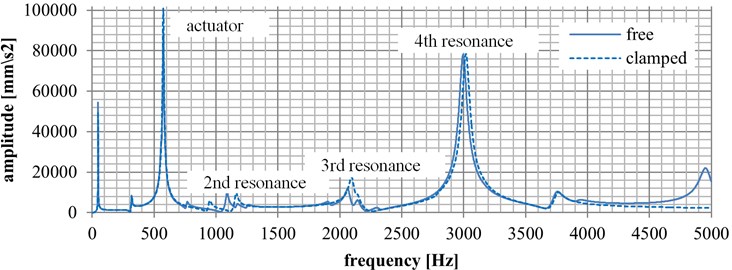
Numerical results from the finite element analysis are presented in Graph 1. The results were focused on natural frequencies with respect to the pre-stress environment. There are two curves. The solid curve represents the state before load (zero value) while the dashed curve represents the state after load (100 N). There are several resonance peaks. The first one occurs at 48 Hz. The second one occurs at 315 Hz. These two frequencies belong to the beam. At 574 Hz, the actuator’s resonance occurs. The marked measurement resonances occur in the range from 1,100 Hz to 3,01 Hz. In the state before load, the second resonance exists at 1,078 Hz. The third resonance is at 2,030 Hz. Finally, the fourth resonance occurs at 3,007 Hz. When measuring the state after load, the second resonance occurs at 1,147 Hz, the third resonance at 2,071 Hz, and the fourth resonance at 3,009 Hz.
As regards amplitudes, the second resonance peak had the amplitude of 0.09109 ms-2 before load, the third resonance had the amplitude of 0.1035 ms-2, and the fourth resonance had the amplitude of 0.77151 ms-2. After the force was applied, the second resonance had the amplitude of 0.09363 ms-2, the third resonance had the amplitude of 0.17116 ms-2, and the fourth resonance had the amplitude of 0.77930 ms-2.
Fig. 3Numerical results
The frequency responses measured as a function of axial pre-stress on the cadaver sample are presented in Fig. 3. The blue curve represents the condition when the axial force is not actuated (zero value). The other, dashed curve represents the condition when the axial force is applied (100 N).
The second resonance frequency is found at 847 Hz before load. The third and fourth resonance frequencies without load are not shown because of large damping effect. In the state after load, the second resonance is found at 1,034 Hz, the third resonance is at 1,961 Hz, and the fourth resonance is at 3,005 Hz.
Fig. 4Experimental results
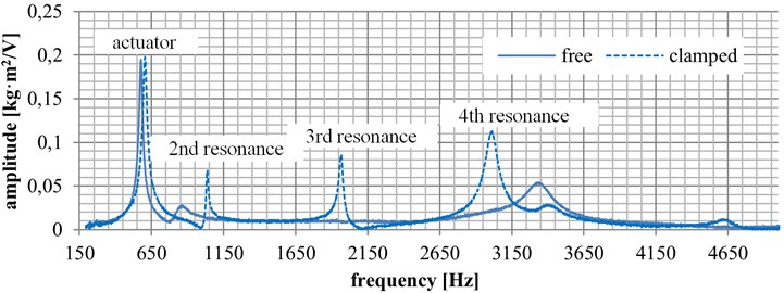
At the initial state (zero value), the second resonance amplitude is 0.027 ms-2, the third and fourth resonances are not shown, probably because of big damping. At the final state (load applied), the second resonance amplitude is 0.068 ms-2, the third resonance amplitude is 0.085 ms-2, and the fourth resonance amplitude is 0.112 ms-2.
4. Conclusions
In this paper, the system of cervical vertebrae and an intervertebral cage was analyzed from frequencies response. It is generally assumed that a frequency response of such a system relates directly to primary stability.
There is a good correlation between experimental and numerical results of the models proposed with respect to the resonance frequencies. The numerical results show resonance frequencies in the range from 150 to 5,000 Hz. These resonances belong to the beam and actuator. Frequencies in the range from 0 to 150 Hz are not considered in the experimental results. The actuator resonance is dominant in both models, and it is the lowest frequency resonance that can be measured in the real situation. For further evaluation, it is necessary to design a new vibration head with a resonance frequency higher than that measured this time. The experimental results suggest that the resonance amplitudes show more variance than the resonance frequencies. From this point of view, the numerical and experimental results do not support each other very well. This might be caused by the damping model simplification. The numerical model confirms that the resonance frequencies move to a higher range if a higher pre-stress force is applied. Either resonance measurement, of amplitude or of frequency, could be a way of defining the primary stability of an implant.
The approach selected is very sensitive to boundary conditions. It is necessary to find and describe all ambient conditions, such as the testing device position, the torque, etc. [3, 5]. After having reached these boundary conditions, correlations through evaluation of the response function can be found. Thus, paving the way to a real world application is difficult. On the other hand, there are not any objective methods to measure the primary stability of a cervical implant. This opens the space to nontraditional methods such as that described here in above.
References
-
Meredith N., Alleyne D., Cawley P. Quantitative determination of the stability of the implant-tissue interface using resonance frequency analysis. Clinical Oral Implants Research, Vol. 7, 1996, p. 261-267.
-
Varini E., Biablocka – Juszczyk E., Lannocca M., Cappello A., Cristofolini L. Assessment of implant stability of cementless hip prostheses through the frequency response function of the stem-one system. Sensors and Actuators A: Physical, Vol. 163, Issue 2, 2010, p. 526-532.
-
Pattijn V., Jaecques S. V. N., De Smet E., Muraru L., Van Lierde C., Van Der Perre G., Naert I., Vander Sloten J. Resonance frequency analysis of implants in the guinea pig model: influence of boundary conditions and orientation of the transducer. Medical Engineering and Physics, Vol. 29, 2007, p. 182-190.
-
Pérez M. A., Moreo P., García – Anznar J. M., Doblaré M. Computational simulation of dental implant osseointegration through resonance frequency analysis. Journal of Biomechanics, Vol. 41, 2008, p. 316-325.
-
Čapek L., Šimůnek A., Slezák R., Dzan L. Influence of the orientation of the Osstell® transducer during measurement of dental implant stability using resonance frequency analysis: a numerical approach. Medical Engineering and Physics, Vol. 31, 2009, p. 764-769.
-
Al-Jetaily S., AlFarraj Al-Dosari A. Assessment of Osstell and Periotest systems in measuring dental implant stability (in vitro study). The Saudi Dental Journal, Vol. 23, 2011, p. 17-21.
-
Schliephake H., Sewing A., Aref A. Resonance frequency measurements of implant stability in the dog mandible: experimental comparison with histomorphometric data. Int. Journal of Oral and Maxillofacial Surgery, Vol. 35, 2006, p. 941-946.
About this article

This work was funded from a Grant by the Ministry of Industry and Trade of Czech Republic FR–TI3/587.
