Abstract
An expansion chamber muffler with the use of a micro-perforated panel (MPP) was developed to improve the acoustic performance. A simulation was carried out using the SysNoise application in the LMS Virtual Lab based on the boundary element method, and the model was verified with the transmission loss measurement using the two-load method and showed good agreement. There was a 40 % accuracy improvement in the BEM model compared to the analytical approach for the simple expansion chamber muffler. The results showed that the performance of this muffler with an 80 mm air cavity depth improved by 75 %, where the transmission loss curve of the muffler became broader, and the hump-shape of the curve was more flat at the top when compared with the performance of a conventional simple expansion chamber muffler. The new muffler with the MPP was applied to a small utility engine with a displacement of 35 cc and the results showed that the noise level was reduced by 20 dBA for the frequency band of 125 Hz to 4000 Hz.
1. Introduction
Passive dissipative mufflers are widely employed to reduce industrial, domestic and vehicle noise. They are a key tool for acoustic comfort control. One of the basic geometries of the mufflers is the simple expansion chamber. The dissipative effect can be achieved by adding porous or fibrous materials inside the chamber resulting in large acoustic damping. It has been reported that fibrous materials are good candidates for noise insulation and can reduce the noise level significantly [1-4]. For cases where clean absorbent is desirable or when the muffler must support high air flux, it is not possible to use fibrous materials. In this kind of application a micro-perforated panel () can be used in a reactive muffler to improve the transmission loss of the muffler.
A is a plate where the perforations are punched or drilled. Typically, it is made of a metal plate or membrane with the diameter of the perforations in sub-millimetres, and where the air cavity between the plate and the backing wall forms the absorber system. The sound absorber with small diameter perforations will provide enough acoustic resistance and enhance the sound attenuation. The , which is made of a metallic plate, is considered to be non-combustible and recyclable, and is suitable for applications in a high temperature environment [5, 6].
Maa established the theory and the design basics for the sheet and characterised the acoustic impedance [7, 8]. The acoustical energy loss in the is similar to that of porous materials where a part of the acoustic energy is transformed into heat due to friction when the acoustic waves pass through the perforations. The rigid wall at the back creates a closed air space system similar to an improved Helmholtz resonator. Typically, the is mainly used for acoustic conditioning of rooms [9].
The has been extensively studied for its efficiency, in particular the parameters and their effects on the sound absorption coefficient [8, 10, 11], such as the acoustic impedance induced by perforations on the and the depth of air cavity backing. Some have considered the effects of vibrations on the which can change the acoustical absorption properties [6, 12-16]. Lee et al. [13, 14] proved that the panel, assisted by the Helmholtz resonator, enhanced the absorption bandwidth of the micro-perforated panel. Parametric studies have shown the different effects of vibrations on the panel and the membrane-type [16].
The improvement of the acoustic performance of the muffler can be achieved by the partitioning of the expansion chamber, the manipulation of the ratio of expansion, and the extending of the inlet and outlet tubes of the muffler [17-19]. The simple expansion chamber muffler has a transmission loss () curve with a typical dome-shape and it is difficult to get a wide band curve. The ability to have a high sound absorption coefficient over a specific frequency range is useful to improve the performance of the simple expansion chamber muffler and this paper discusses the approach to achieve this by careful application of the in the exhaust muffler.
The was applied to the simple expansion chamber muffler and the effect on the sound absorption was evaluated using the computer simulation software, SysNoise, and the model verified against experimental data. The effectiveness of the new muffler was tested on a small utility engine in order to determine its actual performance.
2. Theory
The characterisation of a muffling device used for noise control application in the exhaust of an engine can be described in several parameters. These include the noise reduction (), the insertion loss (), and the transmission loss (). Among these acoustic parameters, the is a relative term and can be calculated and measured relatively fast. Basically, the parameter is defined as the difference in the sound power level between the incident wave exciting the muffler, , and the transmitted wave, , to an anechoic termination [20]:
A simple expansion chamber muffler is a reactive muffler and its transmission loss, , can be determined by the following equation (2) [21, 22]:
Fig. 1(a) shows the general configuration of a simple expansion chamber muffler. In general, the diameters of the inlet and outlet tubes are similar, and is the area expansion ratio of a simple expansion chamber muffler. The maximum and minimum are located at the frequencies, and and can be predicted by the equation below [23]:
where, is the length of the simple expansion chamber muffler and is the integer number.
In the literature, most of the analyses on the performance of mufflers are determined by using the transfer matrix method (), which is based on the plane wave hypothesis. However, this method is limited by the cut-off frequency of the muffler, where it is the frequency response stop point for the muffler [24]. In order to calculate the of the muffler over a wider frequency range, the boundary element method () is used in the analysis of the performance of the muffler [25].
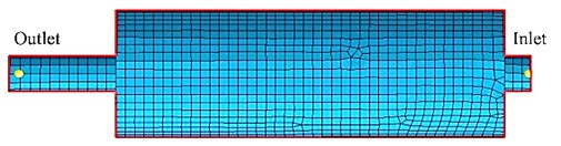
Fig. 1Simple expansion chamber muffler a) without MPP, and b) with MPP
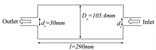
a)
b)
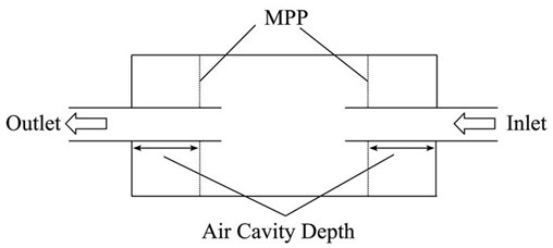
In this study, the is fitted in the simple expansion chamber muffler. For the new design of the muffler, the is installed at both the extended inlet and outlet of the muffler, with an expansion chamber in between, as shown in Fig. 1(b).
The acoustic properties of the sound absorber can be described as an electro-acoustical equivalent circuit, where the specific acoustic impedance is normalised by the air characteristic acoustic impedance and panel porosity [7, 8]. Fig. 2 shows the electro-acoustical equivalent circuit and the configuration layout of the MPP sound absorber.
where:
Fig. 2The typical configuration of a MPP sound absorber (left) and its electro-acoustical equivalent circuit (right) [7, 8]
![The typical configuration of a MPP sound absorber (left) and its electro-acoustical equivalent circuit (right) [7, 8]](https://static-01.extrica.com/articles/14542/14542-img3.jpg)
The acoustic impedance consists of the real and imaginary parts, which represent the acoustic resistance and the acoustic reactance respectively. For equations (6) and (7), the perforation constant is , which is defined as the ratio of the perforation diameter to the viscous boundary layer thickness of the air in the perforation. Typically, the sound absorber is formed by placing the in front of a solid surface and with an air cavity depth of in between. The acoustic impedance of the air cavity behind the is defined below as:
The acoustic impedance of the sound absorber is given by:
For the two-load method of measurement, it is assumed that plane waves are generated in the long impedance tube. The resulting sound field in the tube consists of one component traveling towards the specimen and one reflected component as shown in Fig. 3. The complex sound pressures at the four microphone locations in the tube can be expressed as [26]:
The amplitudes can be expressed in terms of the sound pressures for the four microphones and shown as below:
Fig. 3Schematic of two-load method TL measurement
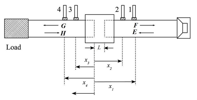
The two-load method of measurement is performed with two different conditions at the end of the tube by terminating with a rigid termination and anechoic termination. The equations (14) to (17) are solved and the transmission loss coefficient for the specimen can be obtained by [27]:
Once the transmission loss coefficient is determined, then the sound can be calculated in unit dB as below:
3. Methodology
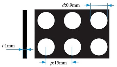
In this study, the simple expansion chamber muffler is fabricated based on the layout in Fig. 1. The general dimensions of the muffler are shown in Fig. 1(a), where the body diameter is 105.4 mm and 290 mm in length. The diameters for the inlet and outlet tubes are 30 mm. A layout of the simple expansion chamber muffler attached with the is shown in Fig. 1(b). In this figure, the application of the in a simple expansion chamber muffler consists of two applied at the extended inlet and outlet of the muffler. The inlet and outlet muffler walls are treated as the backing walls for the to form a sound absorber inside the muffler. The effect of the air cavity depth behind the MPP in the muffler is studied for depths of 20 mm, 40 mm, 60 mm, and 80 mm. The plate is made of aluminium of 1 mm thickness with perforations drilled using a CNC machine with a drill bit of 0.9 mm nominal diameter and arranged with a pitch of 15 mm between the perforations as shown in Fig. 4. The figure shows a one mm thick aluminium plate with square-aligned perforations of 0.9 mm diameter.
Fig. 4The square aligned and round perforation of the MPP
This study is divided into three sections. Section one is a simulation of the muffler for various configurations based on the calculated sound absorption coefficient data, section two is the application of the two-load method for the measurement to verify the data obtained from the simulation analysis, and the third section is the application of the new exhaust muffler design to a small utility engine to ascertain its effectiveness.
3.1. Simulation
In the simulation, the SysNoise software of the LMS Virtual Lab [28], which is based on the BEM acoustic analysis was employed. The value of the sound absorption coefficient of the used in the muffler was modelled based on its acoustic impedance obtained from equation (5). The frequency range of the analysis was between 500 Hz to 5200 Hz which was similar to the experimental measurement frequency range.
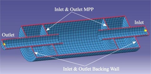
For the modelling process, the circular shape of the simple expansion chamber muffler geometry was constructed in three dimensions in the CAD application environment which was then discretised into small surface elements. Two conditions were investigated to observe the performance of the muffler. The first was where the muffler was modelled as a simple expansion chamber muffler, and all the components inside the muffler were treated as rigid walls with no acoustic impedance. The second condition was where the acoustic impedance was included for the inlet and the outlet of the in the muffler in order to account for the effects of the inside the muffler. The simple expansion chamber muffler model with and without the MPP are shown in Fig. 5 and the cross-sectional view is depicted in Fig. 6. Fig. 5(a) shows the meshing model for the simple expansion chamber muffler without applying the . Fig. 5(b) shows the meshing model for the simple expansion chamber muffler attaching with the MPP at the inlet and outlet tubes. In Fig. 6, it is shown, that the was attached at the inlet and outlet, coupled with the backing wall to form the sound absorbers inside the muffler. In these figures there are two nodes located at the inlet and outlet tubes of the muffler which are used as the points of measurement of the sound pressure at the inlet and outlet tubes for the calculation. There were also two applied in between the tubes to form an expansion chamber.
Fig. 5The meshing model for simple expansion chamber muffler: a) without the MPP or b) with the MPP
a)
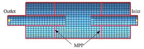
b)
Fig. 6Cross section view of meshing muffler model
The was modelled as a flat plane defined as an absorbent panel with the impedance values determined based on equation (5) [7, 8], and fed into the Absorbent Panel Properties section of the LMS Virtual Lab. The noise source was modelled as the panel velocity with 1 m/s at the inlet of the muffler [29]. In order to obtain the of the muffler, the sound pressure level of the inlet and outlet tubes of the muffler was determined based on the field point meshing.
3.2. Experimental set-up
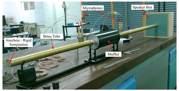
In this study, an experimental test rig was developed to measure the of the fabricated muffler as shown in Fig. 7(a) and 7(b). In Fig. 7(a), the schematic diagram shows the set up consisted of four microphones (BSWA, MA211), two brass tubes, a speaker, a data acquisition unit (LMS SCADAS Mobile, SCM01), and a computer with the analysis software (LMS Test Lab Sound Transmission Loss using impedance tube, TL-ACT.32.9). This experimental set up was based on the two-load method as described by Tao and Seybert [20]. Fig. 7(b) shows the actual system in the laboratory with the muffler installed in the middle of the tube. The frequency range for this study was 500 Hz to 5200 Hz, which was limited by the tube diameter of 30 mm and the distance of 30 mm between the two microphones [30].
Based on Fig. 7, the two-load method required measurement of the sound pressure at four points at the inlet and outlet of the muffler. The excitation signal was a random signal containing all the frequencies of interest coming from a random noise generator which gave the required signal to a loudspeaker at the end of the tube. The signals, which were picked up by the microphones mounted on the inlet and outlet of the muffler, were sent to the computer-controlled data acquisition unit. The measurement was carried out with two different termination conditions at the end of the tube, the anechoic termination and rigid termination as required for the two-load method of measurement of sound . After that, the computer software was used for the analysis of the data and the calculation of the muffler .
Fig. 7The two-load method TL experimental measurement set up: a) schematic diagram, and b) the measurement test rig in the laboratory
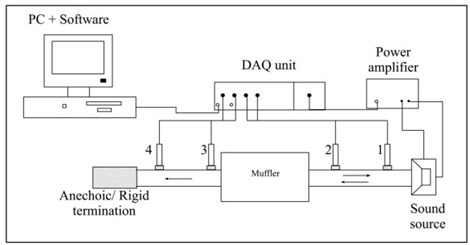
a)
b)
3.3. Engine testing
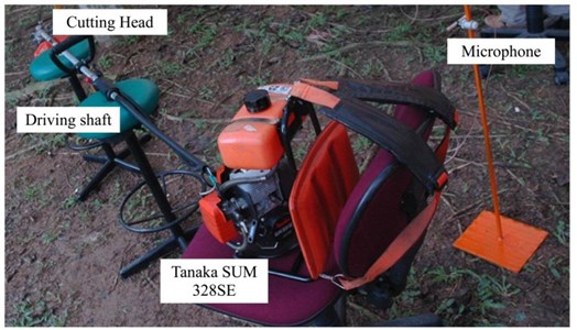
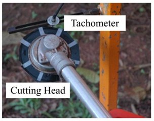
The effectiveness of the new muffler with the was tested by attaching it to the exhaust pipe of a small utility engine used for grass-trimming (Tanaka SUM 328SE). It is a two-stroke engine and it drives the cutting head of the grass trimmer at speeds between 1000 rpm to 6000 rpm. The actual operating speed was determined by using a tachometer (Optel-Thevon) as shown in Fig. 8(b) where it measures the speed of the cutting head and in this test a medium operating speed of 3000±200 rpm was taken as the reference speed for the noise level measurement. This machine is widely used for grass trimming in parks and open areas [31].
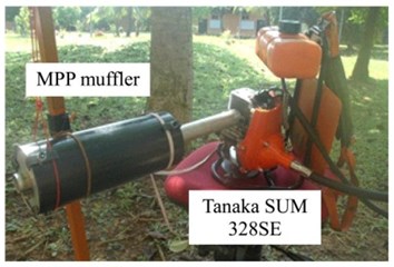
The noise measurement was conducted under two conditions of the un-muffled exhaust and the second when the muffler with the was attached to the exhaust. For the muffled condition, the simple expansion chamber muffler with the and air cavity depth of 80 mm was selected since it gives the broadest band of based on the simulation result (Sec. 5.1). The exhaust noise measurements were made 0.5 m from the end of the muffler outlet with the microphone connected to the LMS Test Express measurement system [32]. The measurement was carried out in an open space to avoid any reflective noise from buildings. The measurement set up as in Fig. 8(a) shows the small utility engine connected to the grass trimmer drive shaft. At the end of the shaft was the cutting head and a microphone was located 5 m from the engine exhaust pipe. The reflective tape was labelled on the cutting head for the tachometer data collecting purpose, which is shown in Fig. 8(b). The operating speed of the engine was determined by the tachometer measurement on the rotational speed of the cutting head. Fig. 8(c) shows the muffler with the mounted on the engine. The sound pressure level before and after the application of the newly designed muffler with the was plotted in 1/3 Octave band.
Fig. 8Exhaust noise measurement: a) measurement set up, b) the tachometer mounted on the top of cutting head, c) the muffler with MPP mount on the engine
a)
b)
c)
4. Results and discussion
4.1. Simulation
Fig. 9 shows the versus frequency for the simple expansion chamber muffler. In this graph, there were three curves obtained from the acoustic simulation analysis, the two-load method measurement, and the analytical model. The analytical was calculated based on the one-dimensional plane wave theory as described in equation (2). Basically, the three curves gave similar dome-shapes repeated every 600 Hz with the peaks and valleys shown for the range of frequency investigated. The maximum and minimum were located at the interval frequency and could be predicted using equations (3) and (4). The results followed a similar trend with the results of Gerges et al. and Potente where the TL curve was also dome-shaped with the peaks and valleys observed at the interval frequency [32, 33]. From this graph, the from the analytical model maintained the same peak level of 16 dB. It shows that the three approaches produce almost similar curves up to 3000 Hz.
For the frequency of 3000 Hz and above, the analytical approach was unable to predict the of the simple expansion chamber muffler accurately as compared with the experimental measurement and the analysis. This shows that the analytical approach is insufficient to predict the performance of the simple expansion chamber muffler compared with the analysis, especially at the higher frequency range. The analysis was able to predict the cut-off frequency of the muffler at 4000 Hz and the error was in the range of 1 % – 5 %. In general, the analysis improved the prediction with an error of 6 dB compared to the analytical approach with a higher error of 8.4 dB. The limitation of the analytical approach was also observed by Andersen where it was unable to capture the higher-order modes [34]. This is because the analytical approach treats the waveform as plane wave, and it does not yield correct results due to the occurrence of the two- and three-dimensional wave motion for the higher frequency range [25].
Fig. 9TL of a simple expansion chamber muffler
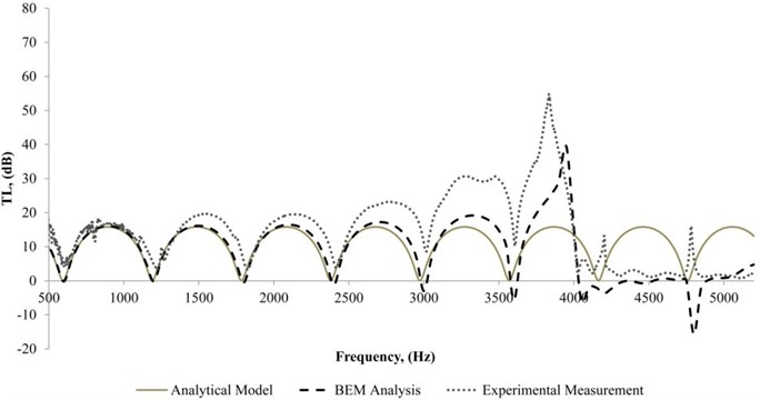
Both results from the and the measurement show that these are comparatively similar and well correlated. The peaks were slightly offset and this was caused by the inaccuracy of parameters, such as densities as mentioned in the study by Andersen [34]. Based on this observation, the simulation approach for the simple expansion chamber muffler is considered valid and correct for the muffler TL prediction since it is comparable with experimental measurements of up to 4000 Hz. The visible differences at frequencies higher than 4000 Hz could be due to the limitations of the muffler including the muffler size, area expansion ratio, and other factors [32]. Therefore, the simple expansion chamber muffler in this study will not work properly for frequencies of more than 4000 Hz.
4.2. Simple expansion chamber muffler – with
The simulation and measurement results after applying the at the inlet and outlet of the simple expansion chamber muffler are shown in Fig. 10-13. The simulation result is represented by the dotted line curve and the solid line is the measurement result. There are four muffler comparison graphs plotted for four different air cavity depths of 20 mm, 40 mm, 60 mm, and 80 mm. The purpose of performing the analysis for different air cavity depths was to determine the acoustic performance of the muffler at different air cavity depths. At the same time, it was also used to determine the reliability and characteristic of the sound absorber applied in the muffler, where the noise attenuation peak was shifted to the lower frequency band with the deeper air cavity depth [35, 36].
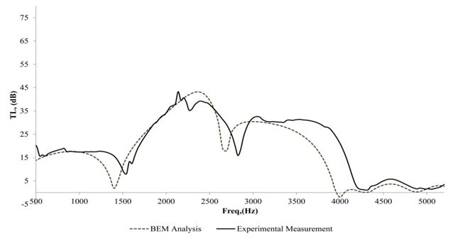
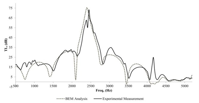
Fig. 10 shows the of the muffler attached with the for both the simulation and the experimental results for air cavity depth of 80 mm. The experimental result shows that the was fairly constant at 15 dB between 500 Hz to 1300 Hz and the was more than 25 dB for the frequency range of 1700 Hz to 2800 Hz. A second hump existed with a peak value of 37 dB. The third hump was quite broad with a relatively constant of 27 dB from 3000 Hz to 3900 Hz. Above 4000 Hz the muffler was no longer effective. It was found that the curve became wider and the humps were smoother. The phenomenon is because the sound absorber with 80 mm air cavity depth plays the dominant role as a noise attenuation component as compared with the relatively small expansion chamber. Therefore, the humps of the curve were insignificant and the curve became broader which matches with the sound absorption property [7, 8].
Fig. 10TL of a simple expansion chamber muffler attached with MPP, and 80 mm air cavity depth
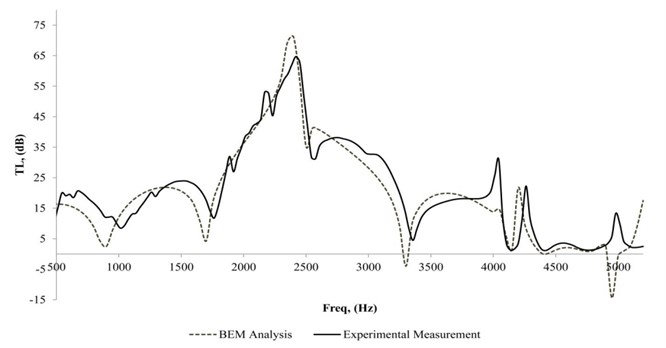
There is another result of the muffler attached with the for the air cavity depth of 60 mm for both the measurement and simulation results as depicted in Fig. 11. The experimental result shows the peak occurred at the third hump with 60 dB at 2400 Hz. The value of the was more than 20 dB for the frequency range of 1500 Hz to 3000 Hz. For the first hump and the third hump of the curve, there was generally more than 15 dB. Again, the muffler showed poor performance at 4000 Hz and above. The measured curve for air cavity depth with 40 mm showed an almost similar trend compared with the air cavity depth of 60 mm for the frequency range of 500 Hz to 3500 Hz as observed in Fig. 12. There was a peak at 2400 Hz and the value was 65 dB. It was found that the third hump of measurement gave a rather broad band from 1800 Hz to 3250 Hz effectiveness, which was 15 dB and above. For the higher frequency range of 4000 Hz and above, no significant was obtained. This same phenomenon was observed with the simple expansion chamber muffler, with poor performance at frequencies of more than 4000 Hz.
The smallest air cavity depth analysed in this study was 20 mm and its curve is shown in Fig. 13. The measured peak was observed to drop at 2500 Hz, and its value was 75 dB. It was the highest peak value among the air cavity depths of 80 mm, 60 mm, and 40 mm. When the air cavity depth of the sound absorber was the smallest, it resulted in the highest chamber length expansion ratio. This proves that the phenomenon is similar with the statement by Potente, where the larger muffler length expansion ratio resulted in the greater value of [32]. For the experimental measurement, it was noticed that the value was fairly constant for the frequency range of 500 Hz to 1500 Hz, which was 15 dB. There were three humps which were merged together and gave a wider band of from 1500 Hz to 3500 Hz. Another two small humps occurred at 3500 Hz to 4250 Hz. For 4500 Hz and above, the muffler was no longer effective. The dome-shaped curve was more obvious for the 20 mm air cavity depth since the reflective phenomenon was dominant and the sound absorption of the sound absorber was insufficient.
Fig. 11TL of a simple expansion chamber muffler attached with MPP, and 60 mm air cavity depth
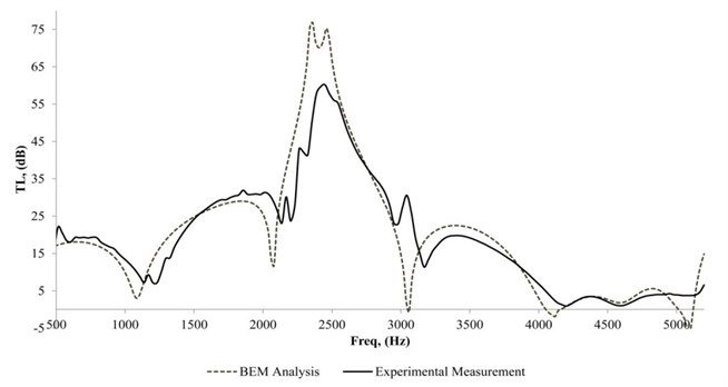
Fig. 12TL of a simple expansion chamber muffler attached with MPP, and 40 mm air cavity depth
For all the cases investigated above, the of the muffler improved significantly with the application of the , and the normal characteristic of the simple expansion chamber muffler was strongly affected by the new design. It was shown that both the curves obtained by the numerical analysis and measurement were in good agreement and comparable. The model [7, 8] used for the acoustic impedance determination was considered valid. At the same time, it was also found that there was no limitation of cut-off frequency analysis using the compared with the plane-wave theory [37]. By using the analysis, the high frequency range of the was also predicted correctly and matched the measurements.
It was observed that the characteristic of the simple expansion chamber muffler after attaching with the was similar to that with the sound absorber as described by Li [34] and Hou [38], where the larger air cavity depth causes the peak to shift to a lower frequency range, and the peak values decrease. Reflective mufflers use the phenomenon of destructive interference to dismiss the noise level and their curve is always dome-shaped as reported by Potente [32] and Gerges et al. [33]. Obviously, the conventional simple expansion chamber muffler gives a similar dome-shaped curve in this study since it is a reflective type of muffler. By considering the application of the , the curve of the muffler improves as the curve becomes smoother with a wider frequency band.
Fig. 13TL of a simple expansion chamber muffler attached with MPP, and 20 mm air cavity depth
Four different air cavity depths were used in order to validate the simulation model. All the four simulation results showed good agreement and matched the measurement results with an error of 4.7 dB. Thus it can be considered that the simulation model is able to model the characteristic of the real muffler, which is useful since it allows the designer to simulate the performance in the early stages of the design.
4.3. engine exhaust noise level measurement of a muffler with MPP
The un-muffled and muffled exhaust noise spectrums of the grass-trimming machine (Tanaka SUM 328SE) for idle and 3000±200 rpm running conditions are shown in Fig. 14 and Fig. 15. From Fig. 14, at the engine idle speed, the noise level for the un-muffled engine produced high sound pressure levels of approximately 100 dBA for the frequency bands of 630 Hz and 800 Hz. It can be seen from Fig. 14 that there was not much reduction for the low frequency bands and high frequency bands after applying the newly designed muffler with the . However, the sound pressure level was reduced to 70 dBA for the frequency bands of 160 Hz to 1000 Hz. There was about 5 dBA to 23 dBA decrement with the use of the new muffler for the engine.
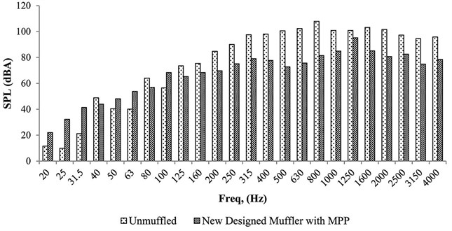
For the condition where the engine was running at higher speeds, the noise level also increased relatively. At 3000±200 rpm, the un-muffled and muffled noise spectra are shown in Fig. 15 where the highest noise level increased to 107 dBA compared to 95 dBA at the idle engine speed. At the same time, the new muffler reduced the noise level to 85 dBA for the broader frequency, which was between 125 Hz to 4000 Hz. However, it was observed that at 3000±200 rpm, the 1250 Hz band was the dominant frequency, where the muffler was unable to reduce the noise level significantly. The same phenomenon could also be noticed for the engine idle speed. This was most probably caused by the resonance of the new system due to the extra mass and stiffness associated with the muffler [32]. It was also observed that the noise level for certain bands at the lower frequencies of less than 125 Hz increased after attaching the new muffler. The undiminished noises were located at the low frequency range, which may have come from the plate vibration at the exhaust pipe connection, engine casing, and the drive shaft. This phenomenon can be reduced by introducing the vibration isolation treatment such as engine rubber mount, hard rubber mat between the exhaust pipe connection, and vibration isolation engine support frame [31, 32].
Fig. 14Muffled and un-muffled engine exhaust noise during idle condition
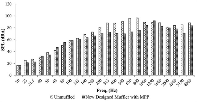
Fig. 15Muffled and un-muffled engine exhaust noise during 3000±200 rpm running condition
5. Conclusion
The acoustic simulation analysis on the simple expansion chamber muffler by using the LMS Virtual Lab – acoustic package was carried out successfully. The results of the simulation for the simple expansion muffler with and without the were in good agreement with the measurement which validated the simulation model. There was 40 % accuracy improvement in the numerical analysis compared to the analytical approach for the simple expansion chamber muffler. The numerical analysis was able to simulate the muffler performance accurately for the higher frequency range and capture the cut-off frequency of the muffler with an error in the range of 1 % – 5 %.
From this study, the of a simple expansion chamber muffler improved significantly with a wider frequency band after applying the . The improvement occurred at a frequency band in between 1000 Hz to 3500 Hz. The curve of the muffler also was affected by the length expansion ratio of the chamber. In general, both the simulation and the experimental measurement results had the same trend and were repeatable for different air cavity depths. The error of the numerical analysis for the muffler with was 4.7 dB. At the same time, the new muffler with the reduced the noise level of the exhaust of the small utility engine. There was a 20 dBA reduction in the sound pressure level of the engine running at 3000±200 rpm for the frequency band of 125 Hz to 4000 Hz.
References
-
Teli M., Pal A., Roy D. Efficacy of nonwoven materials as sound insulator. Indian Journal of Fiber and Textile Research, Vol. 32, 2007, p. 202-206.
-
Senguptaa S. Sound reduction by needle-punched nonwoven fabrics. Indian Journal of Fiber and Textile Research, Vol. 35, 2010, p. 237-242.
-
Na Y. J., Lancaster J., Casali J., Cho G. Sound absorption coefficients of micro-fiber fabrics by reverberation room method. Textile Research Journal, Vol. 77, Issue 5, 2008, p. 330-335.
-
Delany M. E., Bazley E. N. Acoustical properties of fibrous absorbent materials. Applied Acoustics, Vol. 3, Issue 2, 1970, p. 105-116.
-
Herrin D., Liu J., Seybert A. Properties and applications of micro perforated panels. Sound and Vibration, Vol. 45, 2011, p. 6-9.
-
Wu M. Q. Micro-perforated panels for duct silencing. Noise Control Engineering Journal, Vol. 45, Issue 2, 1997, p. 69-77.
-
Dah-You M. Theory and design of micro-perforated panel sound absorbing constructions. Scientia Sinica, Vol. 18, 1975, p. 38-50.
-
Dah-You M. Potential of micro perforated panel absorber. Journal of the Acoustical Society of America, Vol. 104, Issue 5, 1998, p. 2861-2866.
-
Sakagami K., Morimoto M., Yairi M. Application of micro perforated panel absorbers to room interior surfaces. International Journal of Acoustics and Vibration, Vol. 13, Issue 13, 2008, p. 120-124.
-
Sakagami K., Morimoto M., Yairi M., Minemura A. A pilot study on improving the absorptivity of a thick micro perforated panel absorber. Applied Acoustics, Vol. 69, Issue 2, 2008, p. 179-182.
-
Fuchs H. Alternative fibreless absorbers – new tools and materials for noise control and acoustic comfort. Acta Acustica united with Acustica, Vol. 87, Issue 3, 2001, p. 414-422.
-
Miasa I. M., Okuma M. Theoretical and experimental study on sound absorption of a multi-leaf micro perforated panel. Journal of System Design and Dynamics, Vol. 1, Issue 1, 2007, p. 63-72.
-
Lee Y., Sun H., Guo X. Effects of the panel and Helmholtz resonances on a micro-perforated absorber. International Journal of Applied Mathematics and Mechanics, Vol. 4, 2005, p. 49-54.
-
Lee Y. Y., Lee E. W. M., Ng C. F. Sound absorption of a finite flexible micro-perforated panel backed by an air cavity. Journal of Sound and Vibration, Vol. 287, Issue 1-2, 2005, p. 227-243.
-
Kang J., Fuchs H. V. Predicting the absorption of open weave textiles and micro-perforated membranes backed by an air space. Journal of Sound and Vibration, Vol. 220, Issue 5, 1999, p. 905-920.
-
Sakagami K., Morimoto M., Yairi M. A note on the effect of vibration of a micro perforated panel on its sound absorption characteristics. Acoustical Science and Technology, Vol. 26, Issue 2, 2004, p. 204-207.
-
Middelberg J., Barber T. J., Leong S., Byrne K. P., Leonardi E. Computational fluid dynamics analysis of the acoustic performance of various simple expansion chamber mufflers. Proceedings Acoustics 2004, Gold Coast, 2004, p. 123-127.
-
Selamet A., Denia F. D., Besa A. J. Acoustic behaviour of circular dual-chamber mufflers. Journal of Sound and Vibration, Vol. 265, Issue 5, 2003, p. 967-985.
-
Selamet A., Ji Z. L. Acoustic attenuation performance of circular expansion chambers with extended inlet/outlet. Journal of Sound and Vibration, Vol. 223, Issue 2, 1999, p. 197-212.
-
Tao Z., Seybert A. A review of current techniques for measuring muffler transmission loss. Proceedings of the SAE Noise & Vibration Conference and Exhibition, Traverse City, 2003.
-
Bhattacharya P., Panua R., Bose P. K., Ghosh B. Design of reactive muffler for study on the noise level and performance of a two cylinder four stroke 16 h. p. diesel engine. Noise & Vibration Worldwide, Vol. 39, Issue 8, 2008, p. 24-27.
-
Ma J. S., Yang B., Zhuang D. M., Liu Z. F., Dang Z. Q., Zhou L., Dia N. Study of the basic structure of reactive muffler. Advanced Materials Research, Vol. 452-453, 2012, p. 307-311.
-
Wu T. Control of diesel engine exhaust noise. Proceedings of SAE, New York, 1970.
-
Wu C. H., Wang C. N. Attenuation for the simple expansion chamber muffler with a right angle inlet. Journal of Mechanics, Vol. 27, Issue 3, 2011, p. 287-292.
-
Soenarko B., Seybert A. Visualization of wave propagation in muffler. Journal of Visualization, Vol. 3, Issue 3, 2000, p. 229-235.
-
Kinsler L. E. Fundamentals of Acoustics. New York, Wiley, 2000.
-
Yousefzadeh B., Mahjoob M., Mohammadi N., Shahsavari A. An experimental study of sound transmission loss (STL) measurement techniques using an impedance tube. Journal of the Acoustical Society of America, Vol. 123, Issue 5, 2008, p. 965-968.
-
Sysnoise R. 5.6 User’s Manual. Belgium: LMS Numerical Technologies, 2003.
-
Vasile O. Transmission loss assessment for a muffler by boundary element method approach. Analele Universitatii "Eftimie Murgu" Resita. Fascicula de Inginerie, Vol. 17, Issue 1, 2010, p. 233-242.
-
ASTM. E1050-98 Standard Test Method for Impedance and Absorption of Acoustical Material using a Tube, Two Microphones and a Digital Frequency Analysis System. 1998.
-
Ko Y. H., Ean O. L., Ripin Z. M. The design and development of suspended handles for reducing hand-arm vibration in petrol driven grass trimmer. International Journal of Industrial Ergonomics, Vol. 41, Issue 5, 2011, p. 459-470.
-
Potente D. General design principles for an automotive muffler. Proceedings of Acoustics 2005, Busselton, 2005, p. 153-158.
-
Gerges S. N. Y., Jordan R., Thieme F. A., Bento C. J. L., Arenas J. P. Muffler modelling by transfer matrix method and experimental verification. Journal of the Brazilian Society of Mechanical Sciences and Engineering, Vol. 27, Issue 2, 2005, p. 132-140.
-
Andersen K. S. Analysing muffler performance using the transfer matrix method. Proceedings of the COMSOL Conference 2008, Hannover, 2008.
-
Li G., Mechefske C. A comprehensive experimental study of micro-perforated panel acoustic absorbers in MRI scanners. Magnetic Resonance Materials in Physics, Biology and Medicine, Vol. 23, Issue 3, 2010, p. 177-185.
-
Cox T., D'Antonio P. Acoustic Absorbers and Diffusers: Theory, Design and Application. New York: Taylor & Francis Group, 2009.
-
Liu H., Lu S., Zeng F., Lu Z., Zhou J. A study on the effects of higher order mode wave on mufflers performance. Modern Applied Science, Vol. 3, Issue 1, 2009, p. 170-175.
-
Hou K. Measurement and Modelling of Micro-Perforated Panels. M. Sc. Thesis, Purdue University, West Lafayette, United States, 2009.
About this article

This study was completed with financial support from the Skim Latihan Akademik IPTA (SLAI), Ministry of Higher Education Malaysia and Universiti Malaysia Perlis (UniMAP). Support from the USM Incentive Grant A/C No 8021002 is also greatly acknowledged. The authors would also like to express their sincere gratitude to Mr. Baharom Awang, Mr. Wan Muhammad Amri, and Mr. Najib for their assistance in the experimental work in the Vibration Lab.
