Abstract
Acoustic/ultrasonic levitation is now widely used in industrial production processes employed in semiconductor, bioengineering nano-scale electronics and other industries where precise positioning is required. This paper describes the development of a new mixed levitation stage combining the ultrasonic and aerodynamic concepts. It is shown that the combination of these two levitation methods improves the levitation stability by reducing the system vibration caused by air vortices and hammer vibration. The proposed structure of the mixed levitation stage is described. The effect of ultrasonic levitation height and the aerodynamic levitation height is analyzed to determine their influence on the supporting ability of the mixed levitation stage. Both the experiments and modeling for the mixed levitation stage are conducted. The supporting ability of the mixed levitation stage is examined by varying the supporting masses and supporting states. A 3D computation model of the mixed levitation stage is constructed and is analyzed using the computational fluid dynamics (CFD) software. The computational and experimental results show that the levitation height of the mixed levitation is close to the sum of the ultrasonic levitation and the aerodynamic levitation heights; this result confirms that the mixed levitation promotes the supporting ability of the working stage.
1. Introduction
In recent years the aerodynamic levitation method has been developed and employed to improve the precision positioning of the working stage up to nanometer level. Many researchers have contributed to the development of aerodynamic levitation theory. Al-Bender has analyzed the dynamic stability of the air levitation and hammer vibration using an active control model [1]. Panzera introduced a new porous rubber mat in the air levitation bearings to improve the levitation stiffness and vibration [2]. Ye found that the recess shapes of the aerostatic bearings had effects on the phenomenon of pneumatic hammering [3]. Chen showed that hammer vibration is an inherent characteristic of the air levitation system based on his theoretical and experimental analysis [4]. Based on the investigations reported in [1-4], it can be concluded that the formation of air vortices is the main cause of vibration in aerodynamic levitation which reduce its supporting ability.
On the other hand, ultrasonic levitation has been successfully used to achieve both the linear and rotating levitation in a noncontact manner in areas requiring precise positioning such as lithography, etching techniques in IC (integrated circuit), semiconductor manufacturing processes etc. [5-11]. The addition of ultrasonic levitation to aerodynamic levitation is expected to promote the supporting ability of the aerodynamic levitation stage. This mixed levitation stage using both the ultrasonic and aerodynamic driving method is proposed in this paper and analyzed both computationally and experimentally.
In this paper, a 3D computational model of the mixed levitation stage is built and analyzed using CFD. The CFD results show that the vortex velocity can be reduced by almost a factor of three by adding the ultrasonic levitation. Experiments are designed to determine the levitation height of the mass under different supporting conditions and loads. The formula for the mixed levitation stage output force is deduced. The results show that the supporting height of the mixed levitation stage using both ultrasonic and aerodynamic levitation is nearly the sum of the individual levitation heights of ultrasonic levitation and of aerodynamic levitation. The results of this research provide the reference value for the vibration controlling field of IC ultra-precision machine stage [12, 13].
2. Design of mixed levitation driving method
The mixed levitation stage is designed and constructed to achieve the combination of ultrasonic levitation and aerodynamic levitation. The mixed levitation working stage is shown in Fig. 1. It consists of a Langevin vibrator to provide ultrasonic levitation and an air inlet to provide the aerodynamic levitation [14]. When the Langevin vibrator is actuated by an ultrasonic wave, it makes the working stage move upwards along the gravity axis. The upper part in the sketch of Fig. 1 is supported by the air using aerodynamic levitation. The lower part in the sketch of Fig. 1 employs ultrasonic levitation.
Fig. 1The mixed levitation working stage
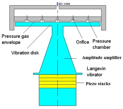
The Langevin vibrator consists of a group of piezoelectric stacks as shown in Fig. 1. The amplitude amplification structure is designed so as to increase the vibration amplitude of the piezoelectric stacks. The relevant parameters needed to determine the levitation characteristics of the Langevin vibrator are shown in Fig. 2.
Fig. 2Parameters required for determining the levitation characteristics of the Langevin vibrator
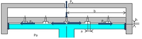
The supporting force of the mixed levitation is critical in determining the output ability of the working stage. We therefore obtain relations between the parameters needed for mixed levitation stage design and its expected resulting output force. The Langevin vibrator used in ultrasonic levitation stage creates an acoustic sine wave displacement of the vibration disk with frequency greater than 20 KHz. The vibration disk of the Langevin vibrator is actuated by the piezoelectric stack as shown in Fig. 1; its velocity output can be expressed as [15]:
where is the velocity amplitude of the vibrating disk, is the actuation time, and is the frequency of the actuating vibrator. For the near field acoustic levitation, the vibration disk can be considered is a flat surface over the ultrasonic Langevin vibrator. Let the levitation height (which is very close to the vibration disk surface) be defined in micron unit. Noting that this height is much smaller than the wavelength of the applied acoustic wave, the ultrasonic levitation pressure can be deduced as [16]:
where is ultrasonic levitation force, is specific heat ratio, is the density of the medium, is the sound velocity in the medium, is the vibration amplitude, and is the levitation height. It can be seen from the Eq. (2), that for the near field acoustic levitation, the ultrasonic levitation force is inversely proportional to the square of the levitation distance if the vibration amplitude remains unchanged. The vibration amplitude is determined by the acoustic levitation input. If the sine wave amplitude driving the Langevin vibrator does not change the vibration amplitude, remains constant. It is important to note from Eq. (2) that the ultrasonic levitation force is inversely proportional to the square of the levitation distance .
For aerodynamic levitation, the aerodynamic force is determined by the difference of the chamber output pressure and the ambient air pressure . The air levitation pressure can is given by [17]:
where is the output pressure of the chamber, is the ambient air pressure, is the chamber radius, and is the radius of the vibration disk. In Eq. (3), the aerodynamic levitation supporting force is proportional to . It has been shown in [18]:
where is height of the aerodynamic levitation. In Eq. (4), , , , and are the gas viscosity, the air flow mass, the gas constant, and gas temperature respectively. From Eq. (3) and Eq. (4), we obtain:
From Eq. (5), it can be noted that the aerodynamic levitation force has nonlinear decreasing functional relationship with the levitation height . Furthermore, the supporting force needed for the working stage becomes bigger as the supported mass becomes bigger as expected. Additionally, it can be seen from Eq. (2) and Eq. (5) that the supporting force and are directly related to the supporting height and .
In the experiment, we first pre-set conditions such that the supporting heights and do not change; they remain small with increasing loads. However it is found that in order to enhance the supporting ability for the same supporting load, the supporting heights and should be bigger. Therefore in the later experiments, the supporting heights are varied to quantify the supporting ability of the mixed levitation stage.
As demonstrated in a later section, the experiments validate that the levitation height of the mixed levitation stage using both the ultrasonic and aerodynamic driving method is the sum of the levitation height of the ultrasonic levitation and the aerodynamic levitation, i.e.:
3. CFD simulations of mixed levitation stage
As mentioned before, formation of air vortices and the hammer phenomenon cause the aerodynamic levitation stage to vibrate which reduces the stability of levitation. The self-excited hammer vibration is a phenomenon caused by the change in chamber output pressure , and is primarily related to the shape of the chamber. We employ the CFD method to investigate whether the air vortices become weaker when the ultrasonic levitation is added to the aerodynamic levitation.
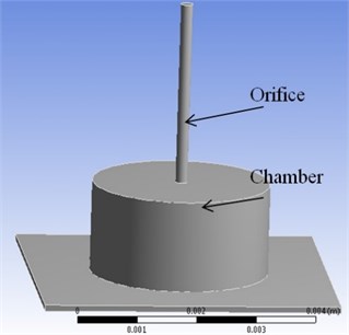
As shown in Fig. 3, the mixed levitation working stage contains several orifices arranged in a linear - distribution; these orifices are assumed to have the same operating conditions. In the simulation, we choose one orifice to analyze its influence on the mixed levitation working stage. For the simulation, the geometric model of the orifice and chamber is built using the actual sizes used in the experimental design of working stage. The height and the diameter of the orifice are 3.5 mm and 0.2 mm respectively. The height and the diameter of the chamber are 1.5 mm and 3 mm respectively. The levitation height and area are set to a size 0.1 mm and 5×5 mm2 respectively.
Fig. 3CFD model of the mixed levitation working stage
After building the geometric model, it is meshed using the ANSYS software GAMBIT. An unstructured mesh of approximately 420,000 tetrahedron cells is generated with average mesh size of 5×10⁻⁵ m. The airflow in the axi-symmetric model is determined and analyzed using the ANSYS CFD software FLUENT. Fig. 4 shows the results of simulation in 2D axial cross-sections.
From Fig. 4 one can notice the vortices at the bottom of the chamber when the working stage is supported only by the air. When air at 5×10⁻² Pa comes through the orifice at velocity of 4.23×10² m/s, its velocity reduces to 8.99×10⁻² m/s due to formation of vortices shown in Fig. 4.
Now the vibration of the Langevin vibrator is added to the aerodynamic levitation. The input sinusoidal velocity to the vibrator is taken as:
It is same as Eq. (1) with velocity amplitude of 500 m/s. Eq. (7) is given as an input in the FLUENT software as a user defined function (UDF). The results of CFD simulation for the mixed levitation stage are shown in Fig. 5.
Fig. 4CFD simulation results for the aerodynamic levitation working stage
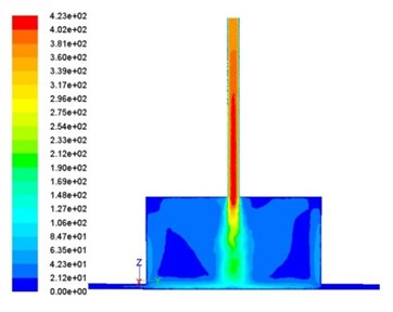
a) Contours of velocity magnitude
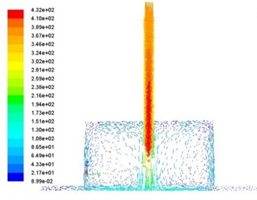
b) Velocity vectors
Fig. 5CFD simulation results for the mixed levitation working stage
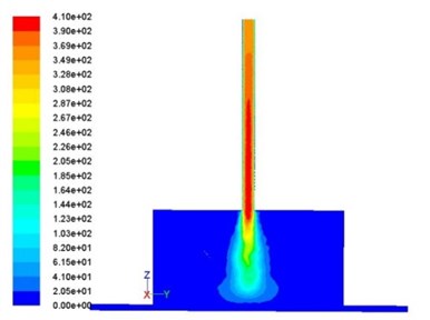
a) Contours of velocity magnitude
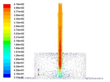
b) Velocity vectors
It can be seen from Fig. 5 that the vortices in the mixed levitation stage have become weaker and the air velocity has reduced to 2.37×10⁻² m/s, which is much smaller than 8.99×10⁻² m/s, the velocity at the exit of the orifice in case of aerodynamic levitation only. These simulations attest to the observation made in the introduction that the addition of ultrasonic levitation to the aerodynamic levitation will decrease the vibration of the working stage.
4. Description of the experimental system
We also conducted an experiment to determine the vibration characteristics and supporting force of the mixed levitation working stage. For this purpose, an experimental analysis system was used; the schematic of the experimental set up is shown in Fig. 6. The main components of the set up are the mixed levitation stage, ultrasonic signal control, oscilloscope, laser micrometer (use as the displacement sensor), the regulator valve (used for air control), and the damping workbench (to isolate the vibrations from the external environment). The mixed levitation stage prototype using both the ultrasonic and aerodynamic driving method is shown in Fig. 7. The experiment employed an in-house built piezoelectric disk.
Fig. 6Schematic of the experimental setup
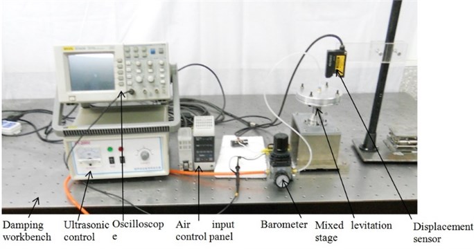
Fig. 7The experimental prototype of the mixed levitation stage
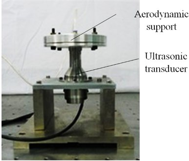
In the experiment, the ultrasonic signal control was adjusted to change the activation voltage of the transducer, which alters the acoustic radiation pressure associated with the Langevin vibrator. The high pressure gas from the air compressor enters into the regulator valve. The control of the regulator valve supplied a constant pressure for aerodynamic levitation.
The aerodynamic levitation floating support was fixed on the Langevin vibrator disk ensuring that the aerodynamic floating support and the Langevin vibrator disk were along the same axis. The ultrasonic signal activated the piezoelectric transducer for achieving the resonant state with changes in the load. The Langevin vibrator generates the radiation pressure driving the floating support to leave the surface of the disk and then the support becomes suspended. The air film due to aerodynamic levitation appears between the Langevin vibrator disk and the floating support.
The experiment includes three operating states: the ultrasonic levitation, the aerodynamic levitation, and the mixed levitation. The levitation heights of different operating states were measured by laser micrometer after the stabilization of the three states. It was found from the experiments that as the levitation load increases, the levitation height reduces as described in the next section.
5. Analysis of experimental results
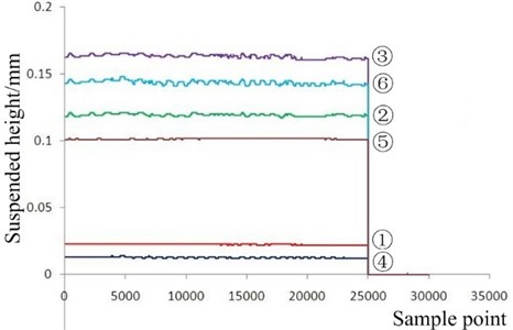
In the experiments, the activation voltage of the Langevin vibrator was kept fixed. 1 kg and 2 kg mass were added to the working levitation stage under three different operating conditions. The results are shown in Fig. 8. It can be seen from Fig. 8 that the suspended height of ultrasonic levitation, aerodynamic levitation and the mixed levitation decrease as the load increases. From Eq. (2), a larger load increases the ultrasonic levitation pressure which causes a decrease in ultrasonic levitation height . Also, from Eq. (5), the aerodynamic levitation height decreases with the aerodynamic levitation height . Therefore, the mixed levitation height decreases as the load increases. Finally as mentioned before, theoretically the levitation height of the mixed levitation is nearly the sum of the levitation height of the ultrasonic levitation and the aerodynamic levitation; the experimental measurements confirm this theoretical prediction.
Fig. 8Experimentally determined levitation height of three different types of levitation – ultrasonic, aerodynamics and mixed under 1 KG and 2 KG loads: 1 – Ultrasonic levitation under 1 KG load, 2 – Aerodynamic levitation under 1 KG load, 3 – Mixed levitation under 1 KG load, 4 – Ultrasonic levitation under 2 KG load, 5 – Aerodynamic levitation under 2 KG load, 6 – Mixed levitation under 2 KG load
6. Conclusions
A novel mixed levitation stage combining ultrasonic and aerodynamic levitation has been analyzed theoretically, computationally using CFD and by experiment. For the design used in this investigation, the CFD simulations show that the aerodynamic levitation stage has the orifice exit velocity of 8.99×10⁻² m/s, velocity which reduces by a factor of four to 2.37×10⁻² m/s after the addition of ultrasonic levitation stage. Both the CFD simulations and experimental data show that the mixed levitation weakens the vortices generated by the aerodynamic levitation and therefore increases the levitation supporting ability. Furthermore, the experiments confirm the predictions of theoretical analysis that the levitation height of the mixed levitation stage is the sum of the ultrasonic and aerodynamic levitation heights.
References
-
F. Al-Bender On the modeling of the dynamic characteristics of aerostatic bearing films: from stability analysis to active compensation. Precision Eng., Vol. 33, Issue 2, 2009, p. 117-126.
-
T. H. Panzera, J. C. Rubio, C. R. Bowen, et al. Microstructural design of materials for aerostatic bearings. Cement and Concrete Composites, Vol. 30 Issue 7, 2008, p. 649-660.
-
Y. X. Ye, X. D. Chen, Y. T. Hu, et al. Effects of recess shapes on pneumatic hammering in aerostatic bearings. Proceedings of the institution of Mechanical Engineers, Part J - Journal of Engineering Tribology, Vol. 224, Issue 3, 2010, p. 231-237.
-
X. Chen, H. Chen, Y. Ye, et al. Air vortices and nano-vibration of aerostatic bearings. Tribology Letters, Vol. 42, 2011, p. 179-183.
-
T.Rudolf, B. Sigurd K. C. The generation of octadecanol monolayers on acoustically levitated water drops. Physicochemical Eng. Aspects, Vol. 309, 2007, p. 198-201.
-
V.Vincent, L. Pierre D. Noncontact handling in microassembly: acoustical levitation. Precision Eng., Vol. 29, 2005, p. 491-505.
-
Y. S.Lee, J. H. Kwon A smart device for particle separation in water using ultrasonic standing waves. Water Science and Technology, Vol. 6, Issue 1, 2006, p. 173-183.
-
Xu G., Li X.T., Su J., et al. Precision evaluation of three-dimensional feature points measurement by binocular vision. J. Opt. Soc. Korea, Vol. 15, Issue 1, 2011, p. 30-37.
-
P. Y. Wang, X. L. Cai Vibrational analysis of planetary gear trains by finite element method. Journal of Vibroengineering, Vol. 14, Issue 4, 2012, p. 1450-1458.
-
Chang Kuotsi A novel ultrasonic clutch using near field acoustic levitation. Ultrasonics, Vol. 43, 2004, p. 49-55.
-
Takeshi Id, James Friend, Kentaro Nakamura A noncontact linear bearing and actuator via ultrasonic levitation. Sensors and Actuators, Vol. 135, 2007, p. 740-747.
-
Xu G., Li X.T., Su J., et al. A method for the estimation of the square size in the chessboard image using gray-level co-occurrence matrix. Meas. Sci. Rev., Vol. 12, Issue 2, 2012, p. 68-73.
-
J. L. Fan, W. P. Huang Numerical simulation research of vortex-induced vibrations of the long circular cylinders with high mass-ratio. Journal of Vibroengineering, Vol. 14 Issue 3, 2012, p. 969-976.
-
Jirí Bok, Vladislav Cápek Langevin approach to the Porto system. Entropy, Vol. 6 Issue 1, 2004, p. 57-67.
-
W. A. Gross Gas Film Lubrication. Wiley, New York, 1962.
-
S. Zhao, Jörg Wallaschek A standing wave acoustic levitation system for large planar objects. Arch Appl Mech, Vol. 81, 2011, p. 123-139.
-
J. P. Khatait, W. Lin, W. J. Lin Design and development of orifice-type aerostatic thrust bearing. SIMTech Technical Reports, Vol. 6, 2005, p. 7-12.
-
Adi Minikes, Izhak Bucher Levitation force induced by pressure radiation in gas squeeze films. Acoustical Society of America, Vol. 116, 2004, p. 217-226.
About this article

The research was funded by the National Natural Science Foundation of China (Grant No. 51075181) and the National Natural Science Foundation of China (Grant No. 50605027).
