Abstract
The propulsion of wing-mounted engine is a typical follower force and may cause significant influences upon wing flutter characteristics. An integrated flutter analysis method has been presented, within which the effects of engine thrusts and geometrical nonlinearities are both considered. Firstly the method has been applied to evaluate the effects of thrusts on the flutter boundary of a high-altitude, long-endurance aircraft wing. The numerical results have an excellent agreement with the published ones. Furthermore the finite element model of a wing carrying two engines has been established, and the influences of propulsion magnitude and position on wing flutter speed are mainly investigated. The results indicated that the effects of engine thrusts are indispensable for wing flutter analysis.
1. Introduction
Modern transporters usually have high-aspect-ratio wings under which the engines are mounted. For this configuration the engine thrusts will couple with the aerodynamics and structure deflection, and this kind of coupling could cause aeroelastic instability. This problem was first investigated by W. T. Feldt [1], where the influences of thrust value on wing flutter speed were presented. The aeroelastic stability of a high-altitude, long-endurance wing subjected to a lateral follower force has been studied by M. J. Patil and D. H. Hodges [2, 3]. The ratio of bending stiffness to torsional stiffness and the value of thrust were considered as key parameters, and their effects on flutter speed and frequency were investigated. It is indicated that under the action of an actual thrust, which was obtained by full-aircraft trimming for a real flight condition, the predicted flutter speed can be changed up to 11 %. S. A. Fazelzadeh and A. Mazidi [4] have studied the bending-torsional flutter characteristics of a wing containing an arbitrarily placed mass subjected to a follower force. Most recently the effects of wing sweep and dihedral angle were also considered by Zhang Jian and Xiang Jingwu [5].
Such problems are much more complicated than conventional aeroelastic analysis, so in the previous literatures wings were all modeled as slender beams. But for a real plane the wing structure is complicated and actually can’t be modeled by a beam accurately. A common method is using the FEM software to establish the structure model [6]. So far, to the author’s knowledge, the researches which study the effects of the engine thrusts on the aeroelastic characteristics of a real, complicated wing structure have not yet been seen.
Based on the secondary development of the MSC/Nastran software with its DMAP language, its static aeroelastic analysis module, nonlinear static analysis module and flutter analysis module were incorporated into an integrated nonlinear flutter analysis procedure. This method can be used for any metal or composite wings with complicated structure and configurations, and the effects of initial angle of attack, external stores, engine thrusts and the geometric nonlinearities are all considered simultaneously.
2. Aerodynamic theory
Since the aim of the present work is to study the subsonic aeroelastic stability of transporters, the non-planar effect of the aerodynamic load is very small and will be ignored here [9, 10]. Considering the design requirements, such delicate design won’t allow airplane to be operated under large angle of attack or even encounter dynamic stall. So the subsonic doublet-lattice theory is adopted here for the flutter analysis [11].
The wing’s lifting surface is discretized and divided into trapezoidal panels, and then the aerodynamic influence coefficients (AICs) are calculated. The non-dimensional downwash velocity at the collocation points can be written in terms of AICs as:
where are the non-dimensional pressures of the lifting elements, is the dynamic pressure of free stream. is the AICs matrix, which is a function of reduced frequency and the free stream Mach number . is the oscillation frequency, is the semi-chord length and is the free stream velocity.
The forces and moments on the wing can be calculated by integrating the pressures over each lifting element, i. e.:
where is the integrating matrix.
In terms of the initial angle of attack of the undeformed wing and the structural deflections, the downwash at collocation points can be written as Eq. (3) explicitly:
where are the displacement vector of structural nodes, is the transformation matrix from the structural deflections to the downwash at collocation points. is the downwash at collocation points caused by the initial angle of attack.
Thus, according to Eq. (1)-(3), the aerodynamic lift and moment can be rewritten in terms of the structural deflections as:
3. Static aeroelastic analysis
After building the nonlinear FEM model of the wing structure and coupling it with aerodynamic model, the steady AICs matrix and the transformation matrix for each Mach number can be extracted from the static aeroelastic analysis module by the DMAP tool. The static aerodynamic lift and moment can be written as:
Then using the nonlinear static analysis module, the structural nonlinear equilibrium equation of the restoring force, aerodynamic load and engine thrusts can be written as:
where is the restoring force due to the structural nonlinear deformation. is the engine thrust, which is a follower force. The structure deformation under the action of aerodynamic load and engine thrusts can be obtained by solving Eq. (6), which is a nonlinear algebraic equation and needs to be solved by iterative loops.
4. Flutter analysis
Ignoring the structural damping, the nonlinear aeroelastic equation of wing can be written as:
The solution for the above equation can be assumed as follows:
where is the steady state value obtained by solving Eq. (6), is the small perturbation with respect to this equilibria. Therefore the aeroelastic equation can be linearized at the steady state, given:
where and are the mass and stiffness matrixes at the steady state . The perturbation of engine thrust can be rewritten as:
where is the stiffness matrix of the follower force generated by engine thrusts.
The normal modes were calculated for the steady state and then the appropriate modes were chosen to reduce the equation. The aeroelastic equation can be rewritten via the generalized coordinates as:
where is the generalized coordinates vector, is the generalized mass matrix, is the generalized stiffness matrix, is the generalized stiffness matrix of follower force, are the generalized aerodynamic loads.
The above matrices were then incorporated into the MSC/Nastran flutter analysis module by DMAP tool and the method is applied to perform flutter analysis. The unmatched flutter velocity and the corresponding flutter Mach number are:
where is the local velocity of sound. Comparing to the initial free stream Mach number given at the beginning of the static aeroelastic analysis: if , then is the matched nonlinear flutter speed. Otherwise reset the free stream Mach number and solve Eq. (6)-(12) again, until the error is converged.
5. Analysis procedures
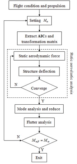
The analysis diagram of present work is shown in Figure 1. Flight condition parameters such as angle of attack, free stream Mach number and engine thrust are given before the analysis. Under this flight condition the steady AICs matrix and the transform matrix are obtained using the static aeroelastic module (Sol 144). Then the structural deflections under the action of aerodynamic loads and the engine thrusts are calculated by means of the nonlinear static analysis module (Sol 106).
In order to approach the steady state, the steady aerodynamic loads are computed again according to the new structural deflections. Thus iterative loops are applied to make the aerodynamic loads match the structural deflections, which finally turn into the actual equilibrium point of the wing. Reduce the equations at the steady state, incorporate the generalized mass and stiffness matrix into the flutter analysis module (Sol 145) and calculate the flutter speed. Repeat the above procedures until the difference between and is converged and the corresponding flutter speed is defined as the nonlinear flutter speed for this flight condition.
Fig. 1Diagram of nonlinear flutter analysis
6. Example 1: HALE wing
The first model to be studied is a high-altitude long-endurance wing and its structural properties and flight conditions are given in Table 1. Its finite element model is established through MSC/Patran software. The wing’s structure is a slender beam which was divided into 32 nonlinear beam elements, and its mass is modeled by 32 lumped mass elements. And 32×5 lifting elements were used for the aerodynamic panel. The wing root is clamped support and a lateral follower force is applied at the position of 15 m from the root in span. The initial angle of attack was not considered in this example. More details of the wing structure can be seen in reference [2].
The parameter , non-dimensional thrust and non-dimensional flutter speed were defined as:
where is the engine thrust, is the half span length, is the flutter speed, is the semi-chord length and is the first uncoupled torsional frequency.
Using the nonlinear flutter analysis method presented above, the influences of parameters and on flutter speed were investigated.
Table 1HALE wing data
Structure data | |
Half span | 16 m |
Chord | 1 m |
Mass per unit length | 0.75 kg/m |
Moment of inertia | 0.1 kg-m |
Spanwise elastic axis | 50 % chord |
Center of gravity of wing | 50 % chord |
Bending rigidity (spanwise) | 2e4 N-m2 |
Bending rigidity (chordwise) | 4e4 N-m2 |
Torsional rigidity | Varies with |
Flight condition | |
Altitude | 20 km |
Air density | 0.889 kg/m3 |
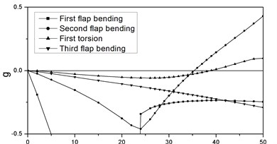
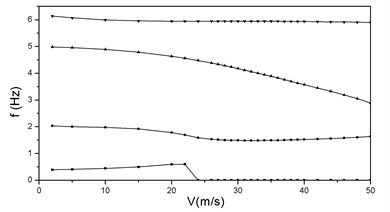
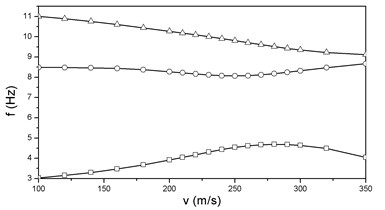
The and locus of HALE wing at the condition of 2 and 2 are shown in Figure 2. When the damping of the first torsional mode crosses the zero axes, the wing is at the critical condition of flutter which means aeroelastic instability. It is seen from Figure 2 that the flutter speed and frequency are 35.3 m/s and 3.76 Hz respectively. This instability is caused by the coupling of the first torsional mode and the second flap bending mode.
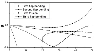
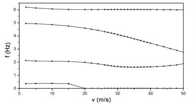
Figure 3 shows the and curves at the condition of 2 and 3. It is seen that there are two instability branches. The flutter speed and frequency are 35.4 m/s and 1.5 Hz, and the flutter modes are the first and second flap bending modes. In contrast with Figure 3, the component of torsional deformation in the flap bending mode increases as the engine thrusts increase, which could result in the variation of flutter form and consequently change flutter speed remarkably.
Fig. 2vg and vf curves at λ= 2, P= 2
a)
b)
Fig. 3vg and vf curves at λ= 2, P= 3
a)
b)
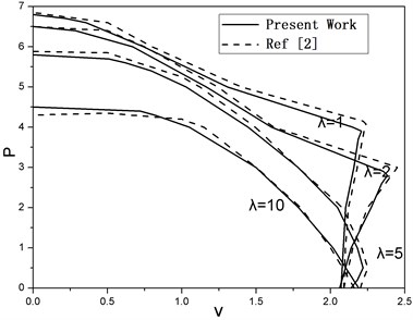
The effect of non-dimensional thrust on flutter boundary for several values of is illustrated in Figure 4. For low levels of thrust the flutter speed increases slightly as thrust goes up. But if the thrust level continues to increase, the curve displays an inflection point which indicates the variation of flutter mode, and this variation leads to a sharp decrease of the flutter speed. The inflection point moves down as increases and disappears gradually while is larger than 5.
Furthermore, for the purpose of method verification, present results are compared in Figure 4 with reference [2] and a good agreement can be achieved. Small differences are observed and can be explained by the fact that the doublet-lattice theory is used here instead of finite-state aerodynamic model used in reference [2]. But the errors are very small and can be ignored in engineering. This simulation example demonstrates the validity of the developed nonlinear flutter analysis procedures.
Fig. 4Effects of λ variation on flutter speed
7. Example 2: a transporter wing with two engines
The finite element model of a wing carrying two engines is shown in Figure 5. It is a traditional metal structural wing, its structure data are given in Table 2. The weight of each engine is 240 kg and the reference thrust is 20000 N. The following two cases are both considered: 1) the propulsion is applied at the front of the engine in order to simulate propeller engine; 2) the propulsion is applied at the end of the engine to simulate jet engine. The thrusts are assumed to be uniformly distributed along the circumferential direction.
Table 2Wing structure data
Half span | 12.43 m |
Chord | 6.06 m |
Taper ratio | 3.88 |
Swept angle | 25 degrees |
Length of store | 3.9 m |
Radius of store | 1.2 m |
Location of first store | 3.36 m |
Location of second store | 7.21 m |
The wing is clamped supported and flight is at sea level with 3° angle of attack, where the air density is 1.225 kg/m3. The parameter is defined as the ratio of engine thrust to the reference thrust.
Table 3 displays the wing tip static deflection for the flow velocity of 246 m/s. The flap bending value is defined as positive while tip goes up and the torsion displacement is positive for nose up. It is seen that the aerodynamic moment makes the wing nose down, while the engine thrusts decrease the torsional deflection and generate nose up pitching moment. This effect is much more obvious when the thrusts were applied at the end of the store. Since the torsional deflection could influence the aerodynamic force, the flap bending displacement will increase under the action of engine thrusts, especially for the case that the thrusts act on the end of the stores.
Fig. 5Model of a wing carrying two engines
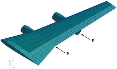
Table 4 compares the natural frequencies of linear and nonlinear models of the wing structure. The aerodynamic loads and the propulsion are not included in the linear model, while the nonlinear model takes such effects into consideration and the corresponding results are calculated for 246 m/s and initial angle of attack of 3°. It is seen that when 0, which means there are only aerodynamic loads acting on the wing, the 1st and 2nd flap bending and 1st torsion frequencies all increase because of the prestressed stiffness generated by structure deformation. When 1 the torsional frequency exhibits a slight decrease because the thrusts alleviate the torsional deflection of the wing structure.
Table 3Wing tip displacement of the nonlinear model at equilibrium position
0 | 1 front | 1 back | |
Flap bending (m) | 0.72 | 0.80 | 0.81 |
Torsion (deg) | -2.20 | -1.73 | -1.65 |
Table 4Comparison of natural frequency results using linear and nonlinear methods (Hz)
Linear | Nonlinear | ||
0 | 1 | ||
First flap bending | 2.77 | 2.83 | 2.83 |
Second flap bending | 8.78 | 8.93 | 8.89 |
First torsion | 10.29 | 11.33 | 11.22 |
Third flap bending | 19.37 | 19.26 | 19.24 |
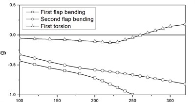
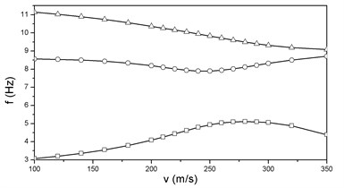
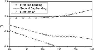
The and curves of the linear model are shown in Figure 6. The flutter speed and frequency are 265.7 m/s and 8.97 Hz respectively. It is clear that the flutter is caused by the coupling of the second flap bending mode and the first torsional mode.
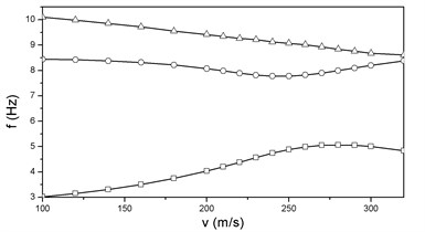
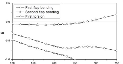
The nonlinear flutter analysis of the wing structure under the action of engine thrusts is performed via the method presented above. The and locus for 0 are illustrated in Figure 7. The corresponding flutter speed and frequency are 273.8 m/s and 9.53 Hz respectively. When 1 and the propulsions are applied at the back end of the engine stores, the flutter speed and frequency are 246.4 m/s and 9.85 Hz respectively, and the and curves are shown in Figure 8. It is observed that for both linear and nonlinear models the instabilities are all of the type of classical bending-torsion coupling flutter. While 1 and the thrusts act at the front of the engine store, the corresponding flutter speed is 249.2 m/s, which is a litter higher than that of the previous one. It’s and curves are similar to Figure 8 and are not necessary to be given again.
It is noted from Figures 6-8 that without propulsion the flutter speed of the nonlinear model is 3.05 % higher than that of the linear model. The flap bending and torsional frequencies are all increased by the effects of prestressed stiffness and geometrical nonlinearity. When the thrusts are applied at the front of the stores the nonlinear flutter speed is 7.26 % lower than the linear one, because of the follower force effect. And this effect is much more obvious when the thrusts are loaded at the back end of the engine stores.
Fig. 6vg and vf curves of linear flutter
a)
b)
Fig. 7vg and vf curves at μ= 0
a)
b)
Fig. 8vg and vf curves at μ= 1 and loaded at the back end
a)
b)
Fig. 9Effects of μ on the wing flutter speed
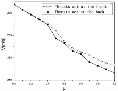
Figure 9 shows the effect of the non-dimensional thrust on the wing flutter speed. It can be observed that the flutter speed exhibits a significant decrease as the thrust level increases, especially when the thrusts are applied at the back end of the stores. Comparing to the case without thrust, the flutter speed of the wing with a reference thrust is decreased by 10.01 % and 8.98 % corresponding to loads acting at the back and front of the nacelle respectively.
8. Conclusion
The purpose of this paper is to investigate the flutter characteristics of a complex structure wing subjected to engine thrusts. To this end an integrated flutter analysis method, which includes the effects of thrusts and geometrical nonlinearity, has been developed based on the secondary development of MSC/Nastran software with its DMAP tool. The aeroelastic stability of a HALE wing, which is subjected to a follower force, has been studied with this method firstly and the effects of several parameters were investigated. The numerical results are compared with published results and an excellent agreement was observed.
The flutter characteristics of a complex wing structure carrying two engines are also analyzed. The influences of the thrust magnitude and location on wing flutter speed are considered. The results show that the flutter speed is 273.8 m/s without thrust and decreased to 246.4 m/s when a 20000 N thrust is applied at the back end of each nacelle. The influences reduce the flutter speed more than 10 %, so the effects of engine thrust are significant and cannot be neglected for wing flutter analysis.
References
-
Feldt W. T., Herrmann G. Bending-torsional flutter of a cantilevered wing containing a tip mass and subjected to a transverse follower force. Journal of the Franklin Institute, Vol. 296, Issue 11, 1974, p. 467-468.
-
D. H. Hodges, M. J. Patil, S. Chae. Effect of thrust on bending-torsion flutter of wings. Journal of Aircraft, Vol. 39, 2002, p. 371-376.
-
D. H. Hodges. Lateral-torsional flutter of a deep cantilever loaded by a lateral follower force. Journal of Sound and Vibration, Vol. 247, 2001, p. 175-183.
-
S. A. Fazelzadeh, A. Mazidi. Bending-torsional flutter of wings with an attached mass subjected to a follower force. Journal of Sound and Vibration, Vol. 323, 2009, p. 148-162.
-
Zhang Jian, Xiang Jinwu. Stability of high-aspect-ratio flexible wings loaded by a lateral follower force. Acta Aeronautic et Astronautic Sinica, Vol. 31, Issue 11, 2010, p. 2115-2123.
-
Xie C. C., Leng J. Z., Yang C. Geometrical nonlinear aeroelastic stability analysis of a composite high-aspect-ratio wing. Shock and Vibration, Vol. 15, Issue 3, 2008, p. 325-333.
-
Ran Yuguo, Han Jinglong, Yun Haiwei. Development of aeroelastic response solution sequence with DMAP language for freeplay nonlinear structure. Journal of Nanjing University of Aeronautics and Astronautics, Vol. 39, Issue 1, 2007, p. 41-46.
-
Ran Yuguo, Liu Hui, Zhang Jinmei, Han Jinglong. Analysis of the nonlinear aeroelastic response for large-aspect-ratio wing. Acta Aerodynamic Sinica, Vol. 27, Issue 4, 2009, p. 394-399.
-
M. J. Patil, D. H. Hodges. On the importance of aerodynamic and structural geometrical nonlinearities in aeroelastic behavior of high-aspect-ratio wings. Journal of Fluids and Structures, Vol. 19, 2004, p. 905-915.
-
Xie Changchuan, Wu Zhigang, Yang Chao. Aeroelastic analysis of flexible large aspect ratio wing. Journal of Beijing University of Aeronautics and Astronautics, Vol. 29, Issue 12, 2003, p. 1087-1090.
-
Guan De. Unsteady Aerodynamic Calculation. Beijing University of Aeronautics and Astronautics Press, Beijing, 1991.
About this article

