Abstract
The Hongshan road tunnels in Nanjing cross up the metro Line 1 tunnel, the closest distance between Hongshan road tunnels and subway tunnels is only 4.14 m. In order to ensure the safety of the subway structure during the Hongshan road tunnels group excavation blasting, the vibration of the subway tunnel was monitored real time. The monitoring results showed that the main frequency distributions of the radial, tangential and vertical vibration of subway tunnel were significantly different. The main frequency and energy of tunnel vibration is mainly concentrated in the high frequency band. This characteristic is very beneficial for the protection of the subway tunnel and catenary. A series of techniques to reduce the vibration were taken during tunnel excavation blasting, which reduced the impact of the blasting vibration to subway tunnel and catenary, and ensured the operation subway safety. The vibration of subway tunnel can be controlled within a certain safety standard with proposed of reducing vibration techniques. It is shown that real-time monitoring and the comprehensive application of the reducing vibration technique are able to guarantee the security of adjacent cross operation subway, which provides references for similar tunnel projects.
1. Introduction
In order to alleviate the congestion status of the city ground transportation, many cities vigorously carry out the underground rail traffic construction. Because of the shallow form of the subway tunnel and the limitation of space near the surface of underground, a large number of cross-tunnel construction emerged in many cities. Mining tunneling method is the common method of tunnel excavation construction [1]. Explosion of the charge complete tunnel excavation, blasting seismic waves inevitably have an adverse impact on the adjacent cross subway. However the blasting vibration safety criterion of the operation subway is not clearly defined in China's current Blasting Safety Regulations. How to ensure the subway normal operation under the effect of blasting seismic wave is particularly important when the adjacent cross subway is operating. Therefore, the study on vibration effects on operation subway induced by blasting of an adjacent cross tunnel and reducing vibration technique is of great significance to ensure the operation subway safety.
Nan Jiang and Jong-Ho Shin studied the effect of excavation blasting on adjacent cross tunnel by numerical method combined with different engineering practice [2-3]. X. Xia analyzed the damage of the surrounding rock and the lining system under adjacent tunnel blast loads and proposed a feasible PPV-based damage control method for different portions of the tunnels [4]. Taking the new-built Line 3 metro under-passing the existing metro Line 4 in Shenzhen as the engineering background, Bo Wang analyzed the interactive dynamic responses between the new-built metro tunnel by blasting construction and the existing operation subway tunnel numerical simulation [5]. However there is little study on the influence of blasting vibration on the subway catenary.
Based on the project of the Nanjing Hongshan Road tunnel group which crosses up the metro Line 1 tunnel, the blasting vibration was real time monitored in this work. The vibration effect on operation subway induced by blasting of an adjacent cross tunnel was researched, and reducing vibration measures for ensuring the metro Line 1 safety are introduced, which can provide references for similar projects.
2. General information of the project
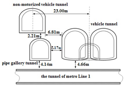
The Nanjing Hongshan Road tunnel group passes through the Red hill. The tunnel group locates in the formation of strong and medium weathered breccia limestone. Parts of the tunnel group locate in eluvium. The groundwater is abundant. The tunnel group consists of two vehicle tunnels, a non-motorized vehicle tunnel and a pipe gallery tunnel used to set the pipeline. The vehicle tunnel and the pipe gallery tunnel cross metro Line 1 tunnel. The distance between the subway tunnel vault and the vehicle tunnel floor is 4.66 m and the distance between the subway tunnel vault and the pipe gallery tunnel floor is 4.14 m. The tunnel group specific positional relationship is shown in Figure 1. The excavation section of the pipe gallery tunnel is horseshoe-shaped. The height of excavation section is 6m, the width is 7.5 m.
The metro Line 1 runs from 6:00-23:00, the time interval between departure trains is about three minutes. The form of the subway tunnel section is horseshoe-shaped, the clear width is 5.3 m and the clear height 5.18 m. The tunnel lining is composite lining structure which consists of the primary support, waterproof layer and secondary lining. The primary support is the anchor spraying C20 concrete, the thickness is 0.3 m. The secondary lining is waterproof reinforced C30 concrete, the thickness 0.3 m. The form of catenary is rigid suspension catenary, the span of the generally is 8 m, but not more than 10 m [6].
Fig. 1Relation position of tunnels in Hong-Shan South Road
3. Field tests of subway blasting vibration
3.1. Real-time blasting vibration monitoring
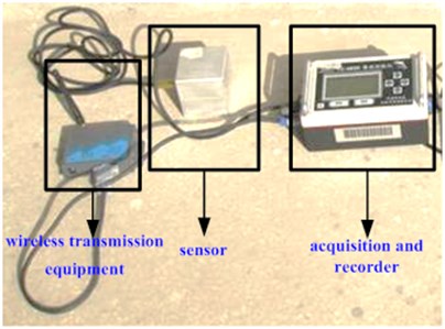
Because the tunnel of metro Line 1 is in the condition of closed management, the vibration signals collected by the blasting vibration meter cannot be read real-time. Therefore, the TC-4850 blasting vibration monitoring system connecting with wireless transmission equipment was used to monitor the tunnel vibration, which is shown in Figure 2. The portable equipments are especially designed for blasting vibration monitor. It has three parallel channels and supports GPRS wireless transmission and SMS alarm. The sampling frequency is 1 KHz-50 KHz. The trigger value can be adjusted.
After the blasting vibration monitoring system record the vibration data, the data including the peak of velocity and the main frequency of tunnel vibration are sent to the designated mobile phone using the GPRS wireless communication means. According to the feedback data of every blasting, the blasting design parameters can be adjusted, so that the blasting vibration does not exceed the safe threshold to ensure the subway safety. In order to avoid vibration of train running in the subway tunnel triggering blasting vibration meter, the trigger value is set as 0.5 cm/s.
Fig. 2TC-4850 blasting vibration monitoring system
3.2. Monitoring points of blasting vibration
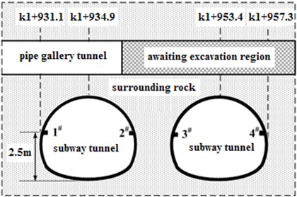
The arrangement of blasting vibration monitoring points includes the position sensor and the number of monitoring points. Research indicates that the maximum vibration speed occurs on tunnel wall and arch section facing the blasting side. The vibration speed at the foot of the wall is relatively small [7]. The upper part of the subway tunnel is electrical equipment for the subway to run. According to the test results that vibration of the floor of subway tunnel is small, so the measuring points were set in the lower part of the tunnel side wall. Considering the relatively location of the tunnels, there are two monitoring points in each subway tunnel, and the total number is four. The specific arrangement of the monitoring points is shown in Figure 3.
Fig. 3Arrangement of subway tunnel vibration monitoring points
3.3. Control criterion of blasting vibration
Table 1The allowable safety standard of tunnel in blasting safety regulations [8]
Protected objects | Allowable safety particle vibration velocity (cm/s) | ||
10 Hz | 10 Hz 50 Hz | 50 Hz | |
Hydraulic tunnel | 7~8 | 8~10 | 10~15 |
Traffic tunnel | 10~12 | 12~15 | 15~20 |
Mine tunnel | 15~18 | 18~25 | 20~30 |
Currently, the popularly used blasting vibration control criterion is a combination of particle vibration velocity and vibration frequency at home and abroad. China's current Blasting Safety Regulations stipulate the safety permitted criterion of different kinds of tunnel under the effect of blasting vibration, which is shown in Table 1. However, there is not the clearly criterion about the operation subway tunnel under the effect of blasting vibration. The safety criterion of general traffic tunnel is unsafe for the operation subway tunnel. A similar project in Hong Kong adopted a more flexible control criterion of velocity, according to the blasting time and the distance between the blasting point and the subway structure. The specific criteria are shown in Table 2. Before blasting monitoring, an investigation to similar project of Shenzhen metro Line 3 was conducted. Comprehensive consideration of the various factors, the blasting vibration control criterion of metro Line 1 is 2 cm/s.
Table 2The control standard of blasting vibration in similar project in Hong Kong [9]
The distance between blasting area and subway structure (m) | Allowable (cm/s) |
3 | Not allow blasting |
3-10 | 2.5 (the period of traffic peak) |
7.5 (not the period of traffic peak) | |
10-20 | 2.5 (the period of traffic peak) |
6.0 (not the period of traffic peak) | |
>20 | 2.5 (the period of traffic peak) |
5.0 (not the period of traffic peak) | |
The period of traffic peak: 7:30-10:30 (Mon.-Sat.), 16:00-19:30 (Mon.-Fri.), 12:30-13:30 (Sat.) | |
4. Analysis of subway tunnel blasting vibration
4.1. Results of blasting vibration tests
The total 369 times blasting were conducted in the process of pipe gallery tunnel construction. The number of the blasting vibration velocity located in the range of 0.5 cm/s~1 cm/s in the monitoring point 1 is 53, 22 located in the range of 1 cm/s~1.5 cm/s, 6 located in the range of 1.5 cm/s~2 cm/s. The number of blasting vibration velocity greater than 2 cm/s is 7. The maximum blasting vibration velocity is 3.54 cm/s in monitoring point 1. Table 3 lists a part of the test results of the pipe gallery tunnel blasting in monitoring point 1. The letters meanings in the table are as follows: , total explosive quantity; , the maximum segment explosive quantity; , radial velocity; , tangential velocity; , vertical velocity; , peak particle velocity; , main frequency. Table 4 shows the delay time of every detonator segment. The high detonator segments are outside the low detonator segments in the same tunnel cross-section.
Table 3The blasting parameters and result of vibration monitoring
Serial number | (kg) | (kg) | Detonator segments | ||||||
(cm/s) | (Hz) | (cm/s) | (Hz) | (cm/s) | (Hz) | ||||
1 | 2.3 | 0.4 | 3,5,7,9,11,12,13 | 0.5790 | 142.9 | 0.5947 | 285.7 | 0.5558 | 250.0 |
2 | 2.0 | 0.4 | 3,5,7,9,12,14 | 0.4359 | 222.2 | 0.587 | 285.7 | 0.5117 | 250.0 |
3 | 1.6 | 0.4 | 5,9,11,12 | 0.4568 | 181.8 | 0.7033 | 285.7 | 0.5393 | 333.3 |
4 | 1.9 | 0.4 | 3,5,7,9,10,11 | 1.0842 | 90.9 | 0.6379 | 285.7 | 0.5161 | 250.0 |
5 | 2.0 | 0.4 | 3,5,7,9,15 | 0.5668 | 100 | 0.8627 | 285.7 | 1.0135 | 399.9 |
6 | 1.8 | 0.4 | 5,7,10,11,12 | 0.5360 | 105.3 | 0.5981 | 285.7 | 0.4918 | 181.8 |
7 | 2.4 | 0.4 | 3,5,7,9,10,11,12 | 0.5756 | 222.2 | 0.639 | 285.7 | 0.5282 | 285.7 |
8 | 4.2 | 1.1 | 3,5,7,13,14,15 | 0.2410 | 250.0 | 0.5061 | 285.7 | 0.2713 | 222.2 |
9 | 2.2 | 0.4 | 3,5,7,9,10,11 | 0.3940 | 222.2 | 0.5172 | 250.0 | 0.5095 | 285.7 |
10 | 2.4 | 0.4 | 5,7,9,10,11,12,13 | 0.4227 | 200 | 0.5981 | 285.7 | 0.5790 | 333.3 |
11 | 2.8 | 0.4 | 3,5,7,9,10,11,12,14 | 0.3885 | 105.3 | 0.6158 | 285.7 | 0.4356 | 285.7 |
Figure 4 shows the radial, tangential and vertical blasting vibration waveform diagram of 11 times blasting in the monitoring point 1. The tangential velocity is maximum in the three directions, the value is 0.6158 cm/s. There are eight detonator segments in this blasting, which can be seen from Table 3. According to the delay time of every detonator segment in Table 4, the waveform of every detonator segment can be identified. The interval time of adjacent velocity peak is equal to the difference of detonator delay time. The charge weight of ms3 and ms14 is 0.2 kg. The charge weight of other segments is 0.4 kg. There are 8 corresponding velocity peaks in the waveform diagram of Figure 4. The corresponding velocity peak of ms3 and ms14 are smaller, other segments are bigger and almost equal.
Table 4The delay time of every detonator segment [10]
Detonator segments | 1 | 2 | 3 | 4 | 5 | 6 | 7 | 8 |
Delay time (ms) | 0 | 25 | 50 | 75 | 110 | 150 | 200 | 250 |
Detonator segments | 9 | 10 | 11 | 12 | 13 | 14 | 15 | 16 |
Delay time (ms) | 310 | 380 | 460 | 550 | 650 | 760 | 880 | 1020 |
Fig. 4The waveform of typical subway tunnel vibration
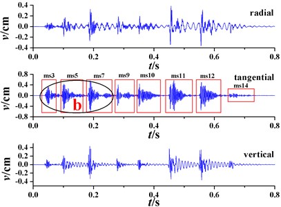
a) The waveform of three directions
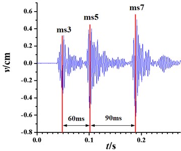
b) The enlarged waveform from picture a)
4.2. Spectrum characteristics of tunnel vibration
Blasting vibration damage to the tunnel is not only closely related with the peak particle velocity, as well as the frequency of vibration. Figure 5 shows the power spectrum density of three directions vibration signal corresponding to waveform diagram of Figure 4. The blasting vibration signal power spectral density of three directions in monitoring point 1 is significantly different, which can be seen in Figure 5. The frequency components of horizontal radial blasting vibration signal are mainly concentrated in three bands. The power spectral density of low frequency is bigger. The frequency corresponding to the maximum power spectral density is 57 Hz. The frequency components of horizontal tangential blasting vibration signal mainly concentrated in the high frequency, less in low-frequency components. The frequency corresponding to the maximum power spectral density is 357 Hz. The frequency component vertical blasting vibration signal is primarily concentrated in the two frequency bands, the power spectral density of the low frequency is bigger, the frequency corresponding to the maximum power spectral density is 99 Hz. Overall, the frequency distributions of three directions blasting vibration signal were concentrated, low-frequency components are less, medium and high frequency components are more.
Generally the natural frequency of the subway tunnel is between 10 to 50 Hz [11]. The natural frequency of rigid suspension catenary with different span is not greater than 10 Hz, which is shown in Table 5. Therefore, the subway tunnel blasting vibration characteristics of high frequency components are more favorable for protecting subway tunnel and rigid suspension catenary.
Fig. 5The power spectral density of vibtration signals in different orientations of point 1
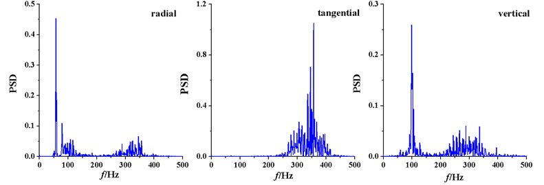
Table 5The natural frequency of rigid suspension catenary with different span (Hz) [12]
Mode degree | 1 | 2 | 3 | 4 | 5 | 6 | 7 | 8 | 9 | 10 |
Span 6 m | 7.468 | 7.482 | 7.482 | 7.523 | 7.592 | 7.687 | 7.808 | 7.954 | 8.122 | 8.313 |
Span 8 m | 4.207 | 4.208 | 4.233 | 4.284 | 4.361 | 4.462 | 4.585 | 4.728 | 4.890 | 5.068 |
Span 10 m | 2.693 | 2.697 | 2.727 | 2.783 | 2.863 | 2.966 | 3.088 | 3.227 | 3.382 | 3.550 |
4.3. Energy characteristics of tunnel vibration
The blasting vibration damage to the subway structure can be seen as the process of energy transfer and conversion. When blasting seismic wave in the tunnel structure, the energy component consistent with the natural frequency of the subway structure will be amplified in the greatest degree. The energy characteristics of blasting seismic wave input the subway structure embodied in the cumulative effect of the target destruction. Therefore, it is necessary to study the energy distribution characteristics of subway tunnel vibration under blasting seismic wave. The wavelet packet analysis is a sophisticated signal analysis method, which can analye the blasting vibration signal energy distribution characteristics in the time domain and frequency domain at the same time. The blasting vibration signal shown in Figure 4 is decomposed with the scale of 11 using the method of wavelet packet. The signal is decomposed to 2048 frequency bands. According to sampling theory, the signal sampling frequency is 4000 Hz, in which case its Nyquist sampling frequency is 2000 Hz. So the width of each band is approximately 1 Hz. According to the energy distribution theory based on wavelet packet, three-dimensional energy distribution of vibration signal in monitoring point 1 is obtained, which is shown in Figure 6.
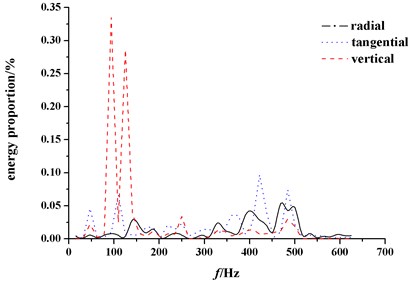
Figure 7 show the comparison of vibration signal band energy distribution in different directions. As shown in Figure 7, in monitoring point 1, the horizontal radial vibration signal energy distribution has two peaks, which located in the medium frequency band; the horizontal tangential vibration signal has several energy peaks, which located in the high frequency band; the vertical vibration signal has only one energy peak, which located in the medium frequency band. The proportion of main frequency band energy in three directions is 13.21 %, 0.16 %, 0.44 % respectively. The frequency band of the largest proportion energy of three directions is 31.25 Hz~46.875 Hz, 453.125 Hz~468.75 Hz, 78.125 Hz~93.75 Hz respectively. The proportions of three energy bands are 18.77 %, 18.09 %, 27.75 %.
In monitoring point 2, the horizontal radial vibration signal energy distribution is more scattered, the energy peak locate in the high frequency band. The energy distribution of the horizontal tangential vibration signal is similar to the distribution in the monitoring 1. The vertical vibration signal has two energy peaks, which are located in the medium frequency band.
It can be seen that the energy distribution of subway tunnel vibration under the effect of blasting seismic wave is mainly in the medium and high frequency, which validates the conclusion above.
Fig. 6Three-dimensional energy distribution of vibration signal in monitoring point 1
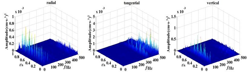
Fig. 7Energy distribution of different frequency bands of different orientations vibration signals
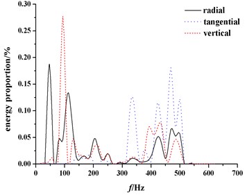
a) The monitoring point 1
b) The monitoring point 2
5. Reduction vibration technique of cross tunnel blasting
5.1. Control the maximum segment explosive quantity
The short circular excavating was adopted in the Hongshan road tunnel group blasting construction, the length of each circular excavating is 1 m. Several blasting were carried out in different part of the same tunnel cross-section. The maximum segment explosive quantity was controlled by increasing the detonator segment and reducing the number of detonate hole at the same time. The millisecond-by-hole initiation using high-precision digital electronic detonators can control blasting seismic wave peak to reduce the tunnel vibration.
5.2. The combination of machine excavation and blasting excavation
Because the cutting holes only have one free surface in tunneling blasting, owing to the clipping action of rock, the blasting vibration produced by the cutting holes is big. For tunnel blasting vibration characteristics, the Hongshan road tunnel group blasting excavation combined with machine excavation. Firstly three empty holes with a diameter of 10 cm were set up in the location of cutting holes, several empty holes with a diameter of 4 cm were set up surrounding the cutting holes, then the rock between empty holes was crushed and hollowed out using the robotic arm, and the cutting holes were gotten. At last other parts of the tunnel cross-section were excavated by blasting. Opening cutting holes with mechanical method increased the free surface of auxiliary holes and surrounding holes, so the blasting vibration was greatly reduced, which ensured the safety of the adjacent subway.
5.3. Empty holes reduction vibration technique
The empty hole around blasting areas can change the blasting seismic wave propagation and played the role of decentralized energy band, which is helpful to reduce the effects of blasting vibration. Multiple rows holes of triangular arrangement have effect of isolating the elastic stress wave [13]. In the Hongshan road tunnel group excavation blasting construction multiple rows empty holes were drilled in the bottom of down steps along the tunnel. The diameter of empty hole were 10 cm, the depth were 5 m, the distance of holes spacing were 40 cm, the distance of row spacing were 40 cm. The empty holes form a buffer zone, which can reduce the influence of tunnel blasting on closed operation subway.
5.4. Active reinforcement measures
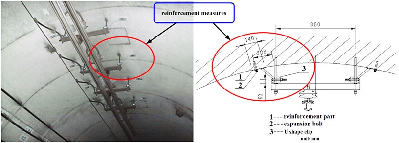
In order to reduce the impact of the tunnel group of blasting vibration on metro Line 1, the active reinforcement measures were taken. The metro catenary, lighting systems, fire systems of subway tunnel were reinforced, where Hongshan Road intersects the metro Line 1. Reinforcement measures change the stiffness of the suspension of rigid catenary, and the natural frequency of the catenary is changed. So the possibility of catenary resonance caused by blasting vibration is reduced.
Fig. 8The reinforcement measures of metro catenary
6. Conclusions
Combined with the project of Hongshan road tunnel group, vibration effect on operation subway induced by blasting of an adjacent cross tunnel and reducing vibration techniques were studied, the main conclusions are as follows:
(1) Project monitoring shows that the particle velocity peak safety threshold of 2 cm/s can ensure operation subway security. This threshold provides a reference for establishing blasting vibration safety standards of operation subway.
(2) The main frequency of the subway tunnel vibration caused by tunneling blasting is mainly in the high frequency band. The energy distribution characteristics of three directions blasting vibration are different, radial energy distribution is dispersed, tangential and vertical is concentration. The energy of three directions mainly distributes in the high frequency, which is advantageous for protection of the subway tunnel structure.
(3) The informational construction means are applied in engineering practice, and good results are achieved. During blasting construction of the Hongshan road, a comprehensive and systematic monitoring was carried out for metro Line 1 tunnel. The monitoring content includes not only real-time blasting vibration monitoring, but also monitoring of regular horizontal clearance convergence, vault crown settlement and surface subsidence. The timely feedback of monitoring results can guide blasting construction. Adjustments of the blasting designs ensure the safety of the blasting operations and the subway structure.
(4) During the process of tunnel blasting, comprehensive applications of controlling the maximum segment explosive quantity, the combination of machine excavation and blasting excavation and empty holes reduction vibration technique can effectively control the blasting vibration. The impact of blasting vibration on the structure of the subway tunnel and catenary can be reduced, which ensure the safety of the operation subway.
References
-
Jingyu Qi. Modern Technology of Tunnel Excavation. Beijing: China Railway Publishing House, 1995, (in Chinese).
-
Nan Jiang, Chuanbo Zhou. Blasting vibration safety criterion for a tunnel liner structure. Tunnelling and Underground Space Technology, Vol. 32, 2012, p. 52-57.
-
Jong-Ho Shin, Hoon-Gi Moon, Sung-Eun Chae. Effect of blast-induced vibration on existing tunnels in soft rocks. Tunnelling and Underground Space Technology, Vol. 26, 2011, p. 51-61.
-
X. Xia, H. B. Li, J. C. Li, B. Liu, C. Yu. A case study on rock damage prediction and control method for underground tunnels subjected to adjacent excavation blasting. Tunnelling and Underground Space Technology, Vol. 35, 2013, p. 1-7.
-
Wang Bo, He Chuan, Xia Weiyang. Study on the interactive dynamic responses between the new built subway tunnel by blasting construction and the existing operation subway tunnel. China Railway Science, Vol. 32, Issue 5, 2012, p. 64-70, (in Chinese).
-
Wang Sheng. Analysis of free vibration of rigid structure suspension of OCS. Electric Railway, Vol. 2, 2005, p. 39-41, (in Chinese).
-
Peng Dao-Fu, Li Zhong-Xian, Yang Nian-Hua. Vibration effect on the working tunnel induced by adjacent blasting. China Railway Science, Vol. 26, Issue 4, 2005, p. 73-76, (in Chinese).
-
Zou Dingxiang. Tunnel blasting for constructing underground in complex environment. The Seventh National Blasting Conference Symposium, Xinjiang: Xinjiang Juvenile Publishing House, 2001, (in Chinese).
-
GB6722-2003 Blasting Safety Regulations. Beijing: China Standard Publishing House, 2004, (in Chinese).
-
GB19417-2003 Detonator with Shock-Conducting Tube. Beijing: China Standard Publishing House, 2003, (in Chinese).
-
Wang Xin, Liu Zeng-Rong. Vibration characteristics of metro tunnel structures based on theory of moderately thick cylindrical shells. Chinese Journal of Geotechnical Engineering, Vol. 33, Issue 5, 2011, p. 762-768, (in Chinese).
-
Mei Gui-Ming, Zhang Wei-Hua. Study on dynamics of rigid suspension catenary. Journal of the China Railway Society, Vol. 25, Issue 2, 2003, p. 24-29, (in Chinese).
-
Xu Ping. Isolation of plane SV waves by discontinuous barriers composed of several rows of cylindrical cavities. Journal of Vibration and Shock, Vol. 28, Issue 12, 2009, p. 84-87.
About this article

We thank the National Natural Science Foundation of China (Grant No. 51178460, 11102233) for financial support. The work presented in this paper also has been funded by the National Key Laboratory of Explosion Science and Technology (Grant No. KFJJ-10-2M).
