Abstract
Based on finite element (FE) method, a dynamic model of a single span blade-rotor-casing coupling system is established. The bearings, bladed rotor, discs and casing are simulated using spring-damping element, beam element, shell element and beam element suitable for curved beam separately (the casing stiffness and damping using spring-damping element). The blade-casing rub-impact is simulated using point-point contact elements; here the corresponding nodes of the blades and the casing are identified as the contact points. To deal with contact constraint conditions and simulate blade-casing frictional characteristics, the augmented Lagrangian method and the coulomb friction model are adopted, respectively. The responses of the system are analyzed under two loading conditions by using variable-step Newmark- integral method combined with Newton-Raphson iteration. The results show that the rub-impact at the second critical speed (case 2) is more serious than that at the first critical speed (case 1). 4× (× denotes the rotating frequency) and its edge frequency components, combination frequency components about 1× can be viewed as distinguishable rub-impact features for cases 1 and 2, respectively. Results can provide theoretical basis for rub-impact diagnosis in blade-rotor-casing coupling systems.
1. Introduction
The distance between the rotating blade and the casing inwall is referred to as tip clearance in rotating machinery, which is one of the important parameters influencing the properties of the rotating machinery [1]. To improve the performance and efficiency of the rotating machinery, a key design for such improvements is minimizing the operational clearances between rotating blade and stationary casing. However, the probability of blade-casing rub-impact increases with the decreasing clearance, which may lead to a catastrophic failure. Most often rub-impact occurs at seals. Seldom, but more dangerous, a blade rubs against the stator or a vane [2] because the high tangential velocity, large impact energy, bending deformation easily relative to the rotor, which can lead to the local damage, such as the loss corner faults of the blade, high cycle fatigue at blade root [3], etc.
Rub-impact problems between the shaft/disc and the seal/casing have been studied for a long time and a large number of papers have been published [4-9]. The present theoretical researches mainly focus on the establishment of rub-impact force model, the dynamic characteristics of the rotor with the blades deformation due to rub-impact and the collision process simulation based on contact dynamics, etc.
For the researches on the rub-impact force model, assuming that the blade fixed at rotor (cantilevered) is flexible and the casing is rigid, Padovan et al. [10] developed a normal blade tip force model based on the mechanical energy balance in a simple configuration blade, and analyzed the nonlinear dynamic characteristics of the system under the condition of single and multiple blade rub-impact. Considering the effects of the bladed disc and rotary centrifugal force on the normal rub-impact force, Jiang et al. [11] developed a new rub-impact force model on the basis of the model of Padovan [10]. Kascak et al. [12] presented two kinds of rub-impact model, smearing and abradable rub models, based on different rubbing forms.
For dynamic characteristics of the rotor with the blades deformation due to rub-impact, assuming the blade as a uniform cantilever beam, Sinha [13] derived the dynamical equations of the rotor-blade-casing system by considering the effect of the rotary inertia, gyroscopic moments, internal material damping in the shaft, external damping in the bearing, torque and axial forces and discussed the transient response of the rotor due to rub-impact during the acceleration and deceleration through the resonance. Lesaffre et al. [14] presented a model of fully flexible bladed rotor developed in the rotating frame and the system dynamical equations including gyroscopic effects, spin softening effects and the centrifugal stiffening effects were obtained by an energetic method. Considering the contact problem between the rotor and the stator as a static problem in some rotational speed ranges and assuming the turbo machine casing as an elastic ring, the complete problem of frictionless sliding contact between the blades and the casing was studied. For the particular condition of local rub-impact, some researchers adopted periodic pulse force to simulate the rub-impact force in the collision process of the blade and the casing [15-17]. Sinha [15] presented a basic dynamical equation for a rotating radial cantilever Timoshenko beam clamped at the hub in a centrifugal force field, and then adopted a periodic pulse load to simulate the local rub-impact against the outer case, and discussed the transient responses of the beam with the tip deformation due to rub-impact in terms of the frequency shift and nonlinear dynamic response of the rotating beam. Turner et al. [16, 17] developed a simplified modeling approach to study the effect of pulsive-type loads on the stiffness behavior of turbomachinery airfoils and quantified the influence of airfoil flexibility based on the relationship between applied force duration and maximum tip deflection.
For the collision process simulation based on contact dynamics, some researchers adopted lumped mass, beam, shell and solid model to simulate the blade, curved beam, used thin wall cylindrical shell to simulate the casing, and reproduced the rub-impact process of the blade and the casing [3, 18-22].
From the analysis of the above literatures, the existing researches seldom consider rotor, blade, casing as a total system, and the research on the effect of the blade-casing rub-impact on the vibration of the rotor system considering the coupling of the bladed rotor and the casing structure is also insufficient. The current paper analyzes the effect of blade-casing rubbing on the nonlinear dynamic characteristics of the flexible bladed rotor. Starting from establishing a dynamic model of a single span blade-rotor-casing system based on the finite element method, the blade-casing rub-impact is simulated using point-point contact elements, where the corresponding nodes of the blades and the casing are identified as the contact points. To deal with contact constraint conditions and simulate blade-casing frictional characteristics, the augmented Lagrangian method and the coulomb friction model are adopted, respectively. The responses of the system are analyzed under two loading conditions by using variable-step Newmark- integral method combined with Newton-Raphson iteration.
The paper is organized as follows: finite element model of the blade-rotor-casing system is described in section 2. In section 3, numerical simulation of rub-impact between the blade and the casing is performed under two loading conditions. Finally, the conclusions are given in the last section.
2. Finite element model of the blade-rotor-casing system
2.1. Rub-impact model based on contact theory
In order to study conveniently, the finite element model of the blade-rotor-casing system is simplified according to the following assumptions:
(a) The blade and the corresponding casing are modeled by constant-section beam and curved beam, respectively;
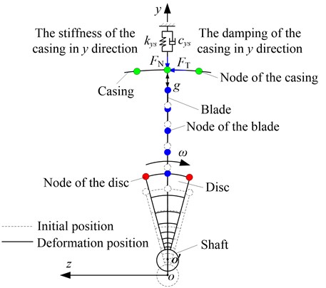
(b) A relatively small sliding in the process of rub-impact is considered, which is similar to point contact between the blade tip and the casing. The rub-impact can be simulated by a point-point contact element with clearance, as is shown in Fig. 1.
For convenience, only part blade-rotor-casing structure is depicted in Fig. 1. The master body is set as the blade and the slave one is the casing. is the gap function of the blade and the casing, and the normal and tangential rub-impact forces, respectively. A contact force between two bodies is always compressive and is active only when the gap between the blade-tip and the outer casing has closed. Assuming that the cross-section of the disc is perpendicular to the axis of rotation and the rub-impact occurs in the plane. is the center of the shaft, the origin of the global coordinate system, whirl angular velocity, and the stiffness and the damping of the casing in direction, respectively.
In this paper the Kuhn-Tucker conditions for Coulomb friction are used for contact detection. In order to ensure mutual non-penetration of the contact boundary of the blade and the casing, the augmented Lagrangian method considering the friction law is selected to deal with contact constraint conditions [22, 23]. The method properly defines force normal to the contact surface to make the penetration limited to a specific tolerance. Such force is as follows:
where is the normal contact stiffness, i.e., the penalty factor, the Lagrange multiplier for (i+1)th iteration, which can be found by:
where is the specific penetration tolerance. After specific iteration, if the penetration is still greater than , the contact stiffness of the contact element will be augmented through the Lagrange multiplier. This procedure is repeated until the penetration is less than .
Fig. 1Rub-impact schematic of the blade and the casing
2.2. Finite element model of the blade-rotor-casing system with rub-impact
Some simplifications about the FE model of the blade-rotor-casing system are introduced as follows:
(a) Shaft and discs are rigidly connected;
(b) Two bearings are identical and simulated ideally by linear stiffness and damping, in addition the cross terms are neglected;
(c) Movements in torsional and axial directions are negligible;
(d) The flexible casing is simulated by linear stiffness and damping. It is modeled by beam element.
Considering the blade-casing rubbing and the external force action, the equation of motion can be written as follows:
where , , , and respectively denote mass, gyroscopic, damping (including bearing, casing and the viscous damping) and stiffness (including bearing, shaft, disc, blade and casing stiffness) matrixes and displacement vector of the global system, is a vector about Lagrange multiplier, the contact constraint matrix in the normal and tangential directions, initial normal gap vector and external load vector. In this paper, the Rayleigh damping form is adopted to determine the viscous part of the total damping matrix and its expression can be written as follows:
where , denote the proportion coefficients of the mass matrix and stiffness matrix, respectively:
Here and denote the first and second critical speeds (r/min), and the first and second modal damping ratios.
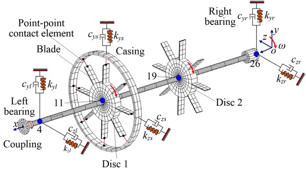
The finite element model of blade-rotor-casing system is given in Fig. 2. In the figure:
(a) Nodes 4 and 26 denote left and right journals, nodes 11 and 19 the connection points of the shaft and disc 1, disc 2;
(b) and denote the stiffness and damping of the bearings, where and denote the stiffness and the damping, subscripts , and , denote , directions and left, right bearings, respectively;
(c) The coupling, shaft and blade are simulated by Beam188 element; disc by Shell181 element; the stiffness and the damping of the bearing and the casing by Combi214 element; the casing using Beam189 element which can take transverse shear effect and initial curvature of the beam into account, namely is suitable for simulating the curved beam; rub-impact between the blade and the casing by Conta178 element; the finite element mesh schematic and model parameters of disc-blade-casing system with rub-impact are shown in Fig. 3 and Table 1.
Fig. 2Finite element model of the blade-rotor-casing coupling system
The shaft and the disc are rigidly connected by coupling DOF and the connection of the disc and the blade is using a sharing node. In order to analyze the influence of the blade-casing rub-impact on the vibration of the shaft and the casing, the vibration responses of node 11 (the shaft) and node 1844 (the casing) will be analyzed in the following sections. Variable-step Newmark- integral method combined with Newton-Raphson iteration is used to solve the nonlinear differential equations considering contact, namely Eq. (3).
Fig. 3Finite element mesh schematic of the disc-blade-casing system with rub-impact
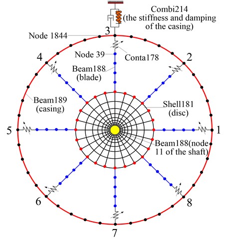
Table 1Model parameters of the blade-rotor-casing system
Parts | Element type | Element number | Geometric parameters | Material parameters |
Coupling | Beam188 | 2 | The details in literature [25] | 210 GPa, 0.3, 7850 kg/m3, 0.04. |
Shaft | Beam188 | 24 | The details in literature [25] | |
Bearing | Combi214 | 2 | 200 MN/m, 500 MN/m, 2 kN·s/m | |
Disc | Shell181 | 384 | The details in literature [25] | |
Blade | Beam188 | 64 | 40 mm, 15 mm, 2 mm, 16 | |
Casing | Beam189 | 40 | 15 mm, 5 mm | |
The stiffness/damping of the casing | Combi214 | 1 | 1 MN/m, 1 kN·s/m | |
Simulation element of the rub-impact | Conta178 | 8 | 80 MN/m |
3. Numerical simulation of the blade-casing rub-impact fault under two loading conditions
Based on the API Standard 617 [26] (Axial and Centrifugal Compressors and Expander-compressors for Petroleum, Chemical and Gas Industry Services, Seventh Edition), the two different unbalance loading conditions are determined according to the modal shape of system, as is shown in Fig. 4. In the figure, and denote the amount of unbalance of disc 1 and 2, respectively. For case 1, 1.56×10⁻⁴ kg∙m and the phases of two unbalances are the same; for case 2, 1.56×10⁻⁴ kg∙m and the phases of two unbalances are opposite. Geometric and material parameters of the blade-rotor-casing system are shown in Table 1. Without rub-impact, unbalance responses of disc 1 (node 11) in direction under two loading conditions are shown in Fig. 5. From the figure, it can be seen that the first order resonant response is predominant in case 1, however the second order resonant response is predominant in case 2. Moreover 1500 r/min and 5700 r/min. It means that the first loading condition excites the first critical speed easily and the second loading condition excites the second critical speed easily. The maximum deformations of the blade-rotor system at the first and second critical speeds are shown in Fig. 6. In the next sections, the numerical simulation for the rub-impact between the blade and the casing will be performed at two critical speeds under two loading conditions in consideration of large vibration amplitude of the rotor.
Fig. 4The schematic of two unbalance load conditions: a) case 1: in-phase of two unbalances, b) case 2: out-of-phase of two unbalances
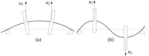
Fig. 5Unbalance responses of the rotor-disc-blade system
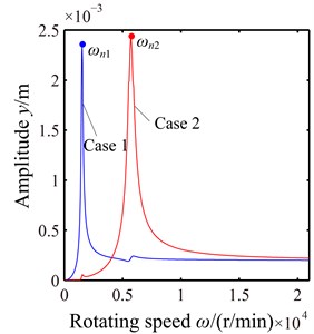
Fig. 6The maximum deformation of the rotor-disc-blade-system: a) the maximum deformation of the rotor-disc-blade-system at the first critical speed under case 1, b) the maximum deformation of the rotor-disc-blade-system at the second critical speed under case 2
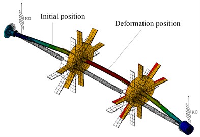
a)
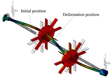
b)
3.1. Dynamic characteristics of the rotor-disc-blade-casing system with rub-impact under case 1
Based on the unbalance response shown in Fig. 5, for case 1, two different initial normal gaps between the blade and the casing ( 2.3 mm and 1.9 mm) are selected to simulate light and serious rub-impact, respectively, at the first critical speed.
The system vibration responses are shown in Fig. 7 when the light blade-casing rub-impact occurs at 2.3 mm. The blade-casing rub-impact creates an amplitude modulated response periodically, and the peak values are near ±2 mm, as is shown in Fig. 7(a). The vibration of the casing is similar to impulse responses caused by periodic rub-impact force, as is shown in Fig. 7(b). Fig. 7(c) shows the rotor orbit after rub-impact. The red point line denotes the initial clearance. It can be concluded from the whirl orbit that the collision of the multiblade against the casing leads to multiple rebounds of the rotor, which makes the rotor orbit similar to the multiple twining circles. Fig. 7(d) shows logarithmic amplitude spectra of the shaft (node 11) and the blade (node 39). Spectrum structure of the blade is more complicated than that of the shaft due to the appearance of more complicated high frequency components. The common feature of them is a wide continuous spectrum peak near 4×, which includes edge frequency components around 4×, such as the components of (4×–5 Hz) and (4×+5 Hz), however 1× is still predominant. The reason is that 4× is close to the second critical speed.
Fig. 7Vibration responses of the blade-rotor-casing system with light rub-impact (g0= 2.3 mm): a) time domain waveform of the shaft (node 11), b) time domain waveform of the casing (node 1844), c) rotor orbit (node 11), d) amplitude spectra of the shaft (node 11) and the blade (node 39), e) normal rub-impact force, f) contact status
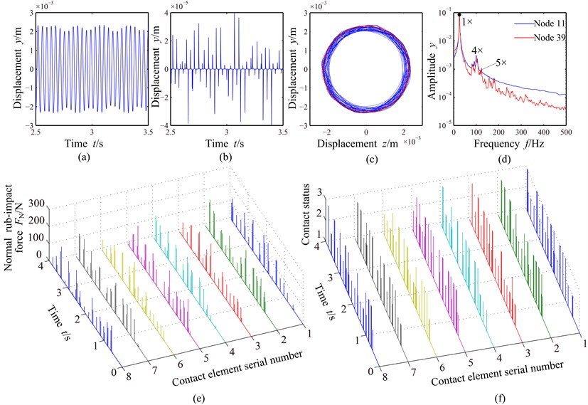
The normal rub-impact forces of eight contact elements are shown in Fig. 7(e), where the right-hand abscissa is contact element serial number shown in Fig. 3. It can be seen from the figure that the normal rub-impact forces fluctuate regularly and the rub-impact periods are not completely the same for different contact elements, which also reflects the disorder of the rub-impact of multiple-blade and the casing. The accurate rub-impact position and the degree of collision can be determined by normal contact force and contact time. The contact statuses of different contact elements with time are shown in Fig. 7(f). For the contact status, “1” denotes non-contact of the blade and the casing, “2” sliding contact and “3” sticking contact (no sliding). It can be concluded from Fig. 7(f) that the sliding and sticking contacts appear alternatively in the rub-impact process, where sticking contact appears at lager normal rub-impact force and sliding contact at smaller normal rub-impact force.
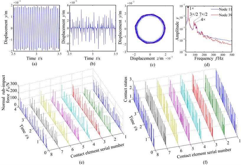
The system vibration responses are shown in Fig. 8 when the serious blade-casing rub-impact occurs at 1.9 mm. The vibration displacement decreases due to the limitation of the casing, as is shown in Fig. 8(a). The displacement of the stator increases slightly and the collision times have a bigger increase compared with those under the light rub-impact condition, as is shown in Fig. 8(b). The rotor orbit shown in Fig. 8(c) is similar to that under the light rub-impact condition. 1/2 fractional harmonic components, such as 3×/2, 7×/2, etc., can be observed, and edge frequency components around 4×, such as (4×–5 Hz) and (4×+5 Hz) also appear in amplitude spectra shown in Fig. 8(d). The rub-impact is more serious due to the increase of collision times and normal rub-impact force compared with those under the light rub-impact condition, as is shown in Fig. 8(e). Sticking contact increases and sliding contact decreases when the blade-casing clearance decreases, as is shown in Fig. 8(f).
Fig. 8Vibration responses of the blade-rotor-casing system with serious rub-impact (g0= 1.9 mm): a) time domain waveform of the shaft (node 11), b) time domain waveform of the casing (node 1844), c) rotor orbit (node 11), d) amplitude spectra of the shaft (node 11) and the blade (node 39), e) normal rub-impact force, f) contact status
3.2. Dynamic characteristics of the rotor-disc-blade- casing system with rub-impact under case 2
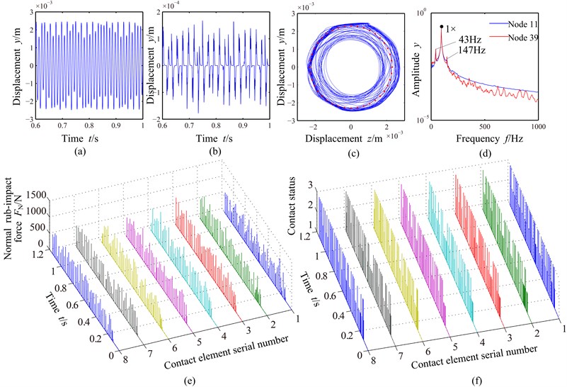
For case 2, the same initial normal gaps between the blade and the casing as case 1 are selected to simulate light and serious rub-impact at the second critical speed. Fig. 9(a) shows that the fluctuation of the vibration amplitude is more violent. The displacement of the stator at case 2 is about 4 times of that at case 1, which shows that the vibration at case 2 is more violent, as is shown in Fig. 9(b). From the rotor orbit shown in Fig. 9(c), it can be seen that the rotor vibration is beyond the clearance of the blade and the casing, which shows that the rotor motion is forward whirl in an annular region and the casing vibrates seriously due to the collision. Combination frequency components about the rotating frequency (1×+95 Hz) appear in the amplitude spectra shown in Fig. 9(d), such as a low frequency component (43 Hz) less than 1× and a high frequency component (147 Hz) greater than 1×, and the sum of low frequency and high frequency is equal to 2×, which shows that the frequency components caused by rub-impact are related to 1×. It can be observed from Figs. 9(e) and 9(f) that the normal rub-impact force (about 1000 N) at case 2 is about five times of that at case 1, the collision is more frequent compared with that at case 1 and the contact status is mainly sticking contact.
Fig. 9Vibration responses of the blade-rotor-casing system with light rub-impact (g0= 2.3 mm): a) time domain waveform of the shaft (node 11), b) time domain waveform of the casing (node 1844), c) rotor orbit (node 11), d) amplitude spectra of the shaft (node 11) and the blade (node 39), e) normal rub-impact force, f) contact status
The vibration responses of the system with serious rub-impact are shown in Fig. 10. The fluctuation of the time domain waveforms shown in Fig. 10(a) increases and the stator vibration shown in Fig. 10(b) is more regular compared with that under light rub-impact condition at case 2. For the rotor orbit shown in Fig. 10(c), it is clear that the orbit is similar under light and serious rub-impact conditions at case 2, which also indicates that the elastic casing can absorb impact energy and weaken the rebound energy acting on the blade. Combination frequency components about 1× appear in the amplitude spectra shown in Fig. 10(d). The low frequency component changes to 44 Hz, the high frequency component 146 Hz and the sum of both is still equal to 2×, which also indicates that combination frequency components can change with the different rub-impact intensity. Compared with light rub-impact, the normal rub-impact force shown in Fig. 10(e) increases slightly. Contact status shown in Fig. 10(f) is similar to that under light rub-impact condition and mainly sticking contact under serious rub-impact condition.
Fig. 10Vibration responses of the blade-rotor-casing system with serious rub-impact (g0= 1.9 mm): a) time domain waveform of the shaft (node 11), b) time domain waveform of the casing (node 1844), c) rotor orbit (node 11), d) amplitude spectra of the shaft (node 11) and the blade (node 39), e) normal rub-impact force, f) contact status
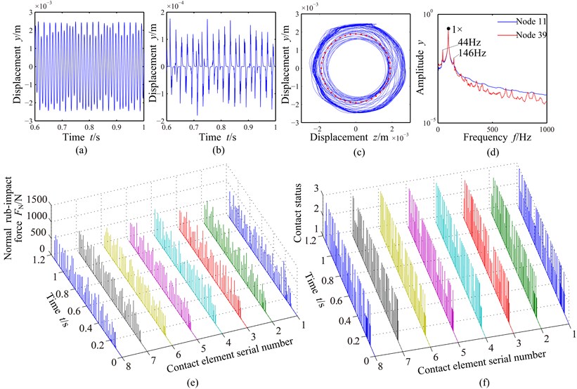
Table 2Rub-impact feature comparison under two loading conditions
Conditions | Rub- impact intensity | Maximum displacement of the casing in y direction (μm) (node 1844) | Typical spectrum features of the shaft (node 11) and the blade (node 39) | Normal minimum/maximum contact force (N) (No. 1 contact element) | Contact status (No. 1 contact element) |
Case 1 | Light | 51 | 4× and its edge frequency components | Minimum: 7.0 Maximum: 189.3 | Sliding contact: 53 times Sticking contact: 14 times |
Serious | 52 | 3×/2,7×/2, 4× and its edge frequency components | Minimum: 6.9 Maximum: 195.7 | Sliding contact: 80 times Sticking contact: 30 times | |
Case 2 | Light | 199 | Combination frequency components about 1×, such as 43 Hz, 147 Hz, 2× | Minimum: 8.1 Maximum: 1042.5 | Sliding contact: 168 times Sticking contact: 58 times |
Serious | 204 | Combination frequency components about 1×, such as 44 Hz, 146 Hz, 2× | Minimum: 6.6 Maximum: 1079.6 | Sliding contact: 169 times Sticking contact: 51 times |
3.3. Fault features comparison under two loading conditions
The detailed fault features including the maximum vibration displacement of the casing in direction, the spectrum features of the shaft and the blade, normal minimum/maximum contact forces and contact status are listed in Table 2 under two loading conditions. In the table, times of sliding contact are more than that observed from the contact status figures (see Fig. 7(f), 8(f), 9(f), 10(f)) because that the many points indicating sliding status are closed to overlap, which also shows that a slight bounce of the blade will appear when intensive sliding status appears. The fewer sticking contact status and shorter contact time show that the rebound of the blade aggravates. For case 1, there are some differences between the contact status and spectrum features but fewer differences in other aspects under light and serious rub-impact conditions. For case 2, the fault features are all similar under the light and serious rub-impact conditions. Compared with case 1, it is clear that the rub-impact has a great influence on the vibration of the rotor and the casing due to the larger normal rub-impact force and more collision times at case 2, which can be proven by the vibration of the stator.
4. Conclusions
In this paper, non-linear vibration characteristics of the rub-impact are investigated by developing the blade-rotor-casing finite element model. In the analytical discussions of the transient response and contact status of the light and serious rubbing under two loading conditions, the conclusions can be obtained as follows:
(1) For the first loading condition which mainly arouses the first order bending resonance, 4× and its edge frequency components appear and the contact status of the blade and the casing is mainly sliding contact under light rub-impact condition; under serious rub-impact condition, 3×/2, 7×/2, 4× and its edge frequency components appear and the collision times and sticking contact times have a great increase than those of light rub-impact.
For the second loading condition which mainly arouses the second order bending resonance, the combination frequency components about 1× appear and the combination frequency value changes slightly with increasing rub-impact intensity.
(2) The rub-impact of the blade and the casing has a small influence on the displacement of the casing, rotor whirl orbit and normal rub-impact force under the first loading condition. Compared with the first loading condition, the rub-impact is more dangerous under the second loading condition because of the larger normal rub-impact force, many collision times, the lower frequency components with larger amplitude and excessive stator vibration.
References
-
Mehalic C. M., Ziemianski J. A. Performance Deterioration of Commercial High-Bypass Ratio Turbo Fan Region. ASME Technical Paper Series 80118, 1980.
-
Muszynska A. Rotor-to-stationary element rub-related vibration phenomena in rotating machinery – literature survey. Vibration Inst., The Shock and Vibration Digest, Vol. 21, Issue 3, 1989, p. 3-11.
-
Liu S. G., Hong J., Chen M. Numerical simulation of the dynamic process of aero-engine blade to case rub impact. Journal of Aerospace Power, Vol. 26, Issue 6, 2011, p. 1282-1288.
-
Muszynska A. Rotordynamics. Boca Raton, CRC Press, 2005.
-
Ahmad S. Rotor casing contact phenomenon in rotor dynamics – literature survey. Journal of Vibration and Control, Vol. 16, Issue 9, 2010, p. 1369-1377.
-
Wen B. C., Wu X. H., Ding Q., et al. Theory and Experiment of Nonlinear Dynamics for Rotating Machinery with Faults. Science Press, 2004.
-
Gao W., Zhang X. J., Zhang Y. Review of nonlinear rotor-dynamics. Journal of Southeast University (Natural Science Edition), Vol. 32, Issue 3, 2002, p. 1-9.
-
Chen Y., Zhang H. Review and prospect on the research of dynamics of complete aero-engine systems. Acta Aeronautica et Astronautica Sinica, Vol. 32, Issue 8, 2011, p. 1371-1391.
-
Chen G., Li C. G., Wang D. Y. Nonlinear dynamic analysis and experiment verification of rotor-ball bearings-support-stator coupling system for aeroengine with rubbing coupling faults. Journal of Engineering for Gas Turbines and Power, Vol. 132, Issue 2, 2010, p. 022501.1-022501.9.
-
Padovan J., Choy F. K. Nonlinear dynamics of rotor/blade/casing rub interactions. Journal of Turbomachinery, Vol. 109, Issue 4, 1987, p. 527-534.
-
Jiang J., Ahrens J., Ulbrich H., et al. A contact model of a rotating, rubbing blade. Proceedings of the 5th International Conference on Rotor Dynamics of the IFTOMM, 1998, p. 478-489.
-
Kascak A. F., Tomko J. J. Effects of Different Rub Models on Simulated Rotor Dynamics. National Aeronautics and Space Administration, Cleveland, OH, Lewis Research Center, 1984.
-
SinhaS. K. Dynamic characteristics of a flexible bladed-rotor with Coulomb damping due to tip-rub. Journal of Sound and Vibration, Vol. 273, 2004, p. 875-919.
-
Lesaffre N., Sinou J. J., Thouverez F. Contact analysis of a flexible bladed-rotor. European Journal of Mechanics – A/Solids, Vol. 26, Issue 3, 2007, p. 541-557.
-
Sinha S. K. Non-linear dynamic response of a rotating radial Timoshenko beam with periodic pulse loading at the free end. International Journal of Non-Linear Mechanics, Vol. 40, Issue 1, 2005, p. 113-149.
-
Turner K., Adams M., Dunn M. Simulation of engine blade tip-rub induced vibration. Proceedings of GT2005, Ren-Tahoe, Nevada, USA, 2005.
-
Turner K., Dunn M., Padova C. Airfoil deflection characteristics during rub events. Journal of Turbomachinery, Vol. 134, Issue 1, 2012, p. 011018-1-011018-7.
-
Legrand M., Pierre C., Peseux B. Structural modal interaction of a four degree of freedom bladed disk and casing model. Journal of Computational and Nonlinear Dynamics, Vol. 5, Issue 4, 2010, p. 13-41.
-
Batailly A., Legrand M., Cartraud P., et al. Assessment of reduced models for the detection of modal interaction through rotor stator contacts. Journal of Sound and Vibration, Vol. 329, Issue 26, 2010, p. 5546-5562.
-
Legrand M., Batailly A., Pierre C. Numerical investigation of abradable coating removal in aircraft engines through plastic constitutive law. Journal of Computational and Nonlinear Dynamics, Vol. 7, Issue 11, 2011, p. 011010.1-011010.11.
-
Legrand M., Batailly A., Magnain B., et al. Full three-dimensional investigation of structural contact interactions in turbomachines. Journal of Sound and Vibration, Vol. 331, Issue 11, 2012, p. 2578-2601.
-
Roques S., Legrand M., Cartraud P., et al. Modeling of a rotor speed transient response with radial rubbing. Journal of Sound and Vibration, Vol. 329, Issue 5, 2010, p. 527-546.
-
Ma H., Shi C. Y., Han Q. K., et al. Fixed-point rubbing fault characteristic analysis of a rotor system based on contact theory. Mechanical Systems and Signal Processing, Vol. 38, Issue 1, 2013, p. 137-153.
-
Simo J. C., Laursen T. A. An augmented Lagrangian treatment of contact problems involving friction. Computers and Structures, Vol. 42, Issue 1, 1992, p. 97-116.
-
Ma H., Tai X. Y., Sun J., et al. Analysis of dynamic characteristics for a dual-disk rotor system with single rub-impact. Advanced Science Letters, Vol. 4, Issues 8-10, 2011, p. 2782-2789.
-
API 617. Axial and Centrifugal Compressors and Turboexpanders for Petroleum, Chemical and Gas Industry Services. American Petroleum Institute, Washington, D. C., 2002.
About this article

We are grateful to the Fundamental Research Funds for the Central Universities (Grant No. N120203001) and Program for New Century Excellent Talents in University (Grant No. NCET-11-0078) for providing financial support for this work.
