Abstract
The study presents a formulation and solution for the problem of damped vibration in T-type frame. The physical model took into consideration the energy dissipation in a vibrating frame as a result of constructional damping in the points of the frame mounting and the supports. As the solution of the problem an influence of constructional damping and system geometry changes on first three eigenvalues of the frame are shown (damped frequencies and vibration amplitude decay rates).
1. Introduction
Vibration damping processes belong to a group of complex and not fully described issues. The purpose of this paper is to analyse the impact of constructional damping of mounting on three rod T-type frame vibration. Modelling of damped vibrations of such frames is important in the engineering practice. It can imitate a range of support structures in which, due to the various factors, motion resistance in joint mounts can occur. Truck crane boom reach changes could be an example of such construction. A simplified model of this system consists of T-type frame with one free end of the horizontal beam. Vibrations of various flat frames types have been repeatedly analysed by different authors. These studies mostly focused on the impact of various types of geometry and load on the frequency of vibration of such systems. In addition the effect of supplementary clustered elements in the form of masses or rotational and translational springs on the dynamics of the frame was studied.
The problem of stability of flat frames was considered in the works [1-3]. In paper [1] the type of instability of a T-type frame with joint mass subjected to a compressive follower force applied at the joint was investigated. Areas of loss of divergent and flutter frame stability were identified. Similar in the work [2] static stability analysis of elastically restrained structures under follower forces was investigated. An influence of rigidity of supports modelled by springs on the type of the loss of stability of the two types of frames, loaded by the follower force, was determined. In the work [3] the effect of deviations from right angle of rectangular frames was studied. Also the individual and primary coupling effects of several parameters upon the load-carrying capacity of this frame were discussed.
Constructions of Γ and T-type frames have quite an extensive literature on the subject. In the research [4] critical load value of closed planar frames was determined. Furthermore course of natural frequencies changes in external load function was appointed. Also adopted construction solutions were taken into account.
In the work [5] the results of theoretical, numerical and experimental research on free vibrations of T-type frame, loaded by longitudinal force directed to its bolt, were presented. The same theoretical, numerical and experimental study associated with a rectangular two-rod frame with reference to stability and free vibrations has been carried out in the work [6]. Post of researched frame realizes load by the force directed toward the pole.
Variational method for investigating the stability of a rectangular two-bar frame was applied in the work [7]. The frame was acted upon by a subfollower force applied at the joint of both members. Due to the nonlinearity behaviour of the system, the problem has been solved using the perturbation method. Research on the modal analysis of the simple Bernoulli-Euler beam also was carried out. In the paper [8] numerical procedure for the complex frequencies and vibration modes evaluation was presented. In addition, in order to decouple the equation of motion, the appropriate orthogonality conditions have been established. In the modal analysis viscous rotary dampers were taken into account.
An example of a rotary dampers application can be found in work [9], in which the influence of constructional damping of actuator supports on its eigenvalues was examined. This paper presents an analysis of the impact of constructional damping of supports (modeled by using hyper viscous rotary dampers) on the dynamics of three-rod flat frame of T-type. The results refer to the influence of the geometry and the size of damping of individual supports on the eigenvalues of the system under study.
2. Physical and mathematical model of T-type frame damped vibrations
The physical model of researched system is shown on Fig. 1. Considered frame consists of three parts of the bending stiffness , , , respectively. Values adopted as mass per length unit were Furthermore it was assumed that and The damping vibration was modeled by placing the individual hyper viscous rotary dampers supports with damping coefficients where
Fig. 1Physical model of the system
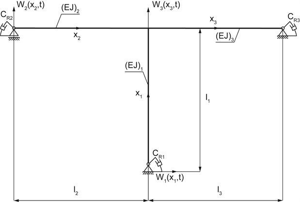
The equations of individual beams motion of considered frame can be written as:
Geometric boundary conditions and continuities are as following:
The boundary problem is supplemented by the natural boundary conditions in the form of:
3. The solution to the problem
The solutions of equations (1) take the form of:
where – frequency of complex number,
By substituting eq. (2) into eq. (1) we obtain:
where
The boundary conditions (after the separation of variables) of considered system are as the following:
The solution of equations (3) are the functions:
where .
After substituting the equations (6) to the boundary conditions (5), system of equations with respect to the unknown constants was obtained. In the matrix form this system can be written as:
where and
The system of equations has a nontrivial solution if the determinant of the matrix by constant equals zero:
As a result of solution of boundary value problem the vibration eigenvalues were obtained. Searched roots are complex numbers in which damped vibration frequencies are presented by the real parts while the system damping is characterized by the imaginary parts .
4. The results of numerical computations
The studies of damped frame vibrations were performed for the following geometrical and material data: Nm2 and kg/m. The length of each rod frame changed in the range of m to m. For the calculation the dimensionless damping parameters were defined as:
In Figures 2-7 further eigenvalues (both and ) were denoted (  ,
,  ,
,  ) respectively.
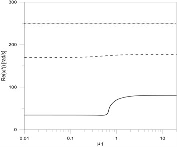
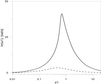
Fig. 2The dependence between the first three eigenvalues: a) real, b) imaginary parts and the damping parameter μ1
a)
b)
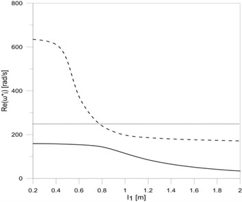
Fig. 3The dependence between the first three eigenvalues: a) real, b) imaginary parts and the length of the vertical frame rod l1
a)
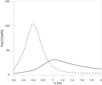
b)
The results of eigenvalue changes research, including damping changes at the vertical rod frame mounting, are shown in Fig. 2. All research results performed for the variable parameters of damping were also performed for the length of each rod frame equal m.
On the other hand, Fig. 3 shows the research results of frame eigenvalue changes related with changes in rod length. In this case the support damping was constant, The same damping values were always assumed during the research of the influence of each rod length on the eigenvalues of the frame.
The research results on eigenvalue and damping changes in the points of vertical frame rod mounting are shown on Fig. 4. The dependence of first three eigenvalues ( and ) on horizontal frame rods m is shown on Fig. 5.
Fig. 4The dependence between the first three eigenvalues: a) real, b) imaginary parts and the damping parameters μ2 and μ3
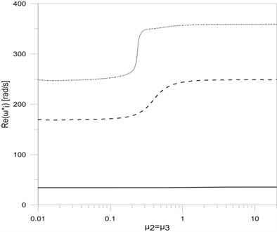
a)
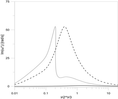
b)
Fig. 5The dependence between the first three eigenvalues: a) real, b) imaginary parts and the length of the horizontal frame rods l2=l3
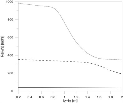
a)
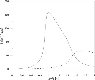
b)
Fig. 6 presents frame eigenvalues changes with simultaneous change of all damping coefficients . Fig. 7 also presents frame eigenvalues changes but with simultaneous change of all rods lengths, with .
Fig. 6The dependence between the first three eigenvalues: a) real, b) imaginary parts and the damping parameters μ1, μ2 and μ3
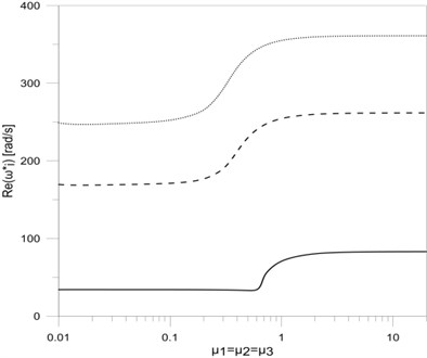
a)
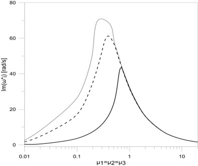
b)
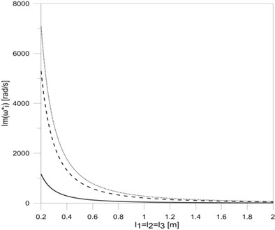
Fig. 7The dependence between the first three eigenvalues: a) real, b) imaginary parts and the length of the frame rods l1=l2=l3
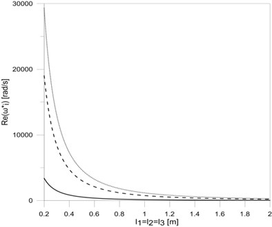
a)
b)
5. Conclusions
In this paper a T-type frame vibration damping model was presented. The vibration damping was implemented by the use of viscous rotary dampers applied in mounting places and supports of the frame. Based on the obtained results it can be concluded that including constructional damping mounting in frame vibration researches causes significant changes in the frame eigenvalues. The change of value of the damping coefficient significantly effects on the first eigenvalue (both for the damped frequency and the frequency decay factor ). In this case the damped frequency increases (Fig. 2(a)) to a value that corresponds with vertical rod clamp mounting, while the frequency decay rate increases to a maximum value and then tends to 0 when . Similar changes both in the damped frequency ( and ) as well as in the frequency decay factor ( and ) can be seen in the case when rotary damper coefficients in horizontal rod mounting places are being changed (Fig. 4(a) and Fig. 4(b)). The changes concern the second and third eigenvalues of the tested frame. The simultaneous change of all damping coefficients in the place of frame mounting and in supports also causes similar waveforms of the real and imaginary parts of all researched frame eigenvalues (Fig. 6(a) and Fig. 6(b)).
Analysing the effect of the lengths of each of the rods on eigenvalues of researched frame (Fig. 3(a), Fig. 3(b), Fig. 5(a) and Fig. 5(b)), it can be concluded that damped vibration frequencies decrease by rod elongation, while vibration frequency decay factors rise to maximum and then decrease. The simultaneous elongation of all frame rods (Fig. 7(a) and Fig. 7(b)) results in a permanent reduction in both the damped frequencies and the frequency decay factors . The possibility of calculating the length of the rod frame for which frequency decay factors are the biggest allows designing rod systems with lengths ensuring the minimal vibration amplitudes of such systems. The proposed mathematical model of T-type frame with constructional damping mounting, after taking into account appropriate boundary, continuity and bonds conditions, can be extended to any more complex system, consisting of a number of simple systems (T-type frames).
References
-
Kounadis A. N., Ecomonou A. P. The effects of the joint stiffness and of the constraints on the type of instability of a frame under follower force. Acta Mech., Vol. 36, 1980, p. 157-168.
-
Kounadis A. N. Static stability analysis of elastically restrained structures under follower forces. Am. Inst. Aeron. Astr. J., Vol. 18, Issue 4, 1980, p. 473-476.
-
Rallis N. S., Kounadis A. N. Nonlinear sway – buckling of geometrically imperfect rectangular frames. Ing. Arch., Vol. 55, 1985, p. 90-97.
-
Przybylski J., Tomski L. Postbuckling behaviour of T-frame with reinfoced vertical bar. Stability of Steel Structures, Vol. 1, 1995, p. 173-180.
-
Szmidla J. Vibrations and stability of T-type frame loaded by longitudinal force in relation to its bolt. Thin-Walled Structures, Vol. 45, 2007, p. 931-935.
-
Szmidla J. Stability and vibrations of type Γ frame loaded by the force directed towards the pole. Stability of Structures, 2009, p. 395-402.
-
Tomski L., Przybylski J., Szmidla J. Stability and vibrations of a two-bar frame under a follower force. Zeit. Ang. Math. Mech., Vol. S5, Issue 76, 1996, p. 521-522.
-
Oliveto G., Santini A., Tripodi E. Complex modal analysis of a flexural vibrating beam with viscous end conditions. Journal of Sound and Vibration, Vol. 200, 1997, p. 327-345.
-
Sochacki W. Influence of structural damping of supports on hydraulic cylinder vibrations. Przegląd Mechaniczny, 2012, Vol. 9, p. 38-42.
About this article

This research was supported by the Ministry of Science and Higher Education in 2013, Warsaw, Poland.
