Abstract
This paper conducts a dynamic design of motorized spindles with different configurations using an integrated dynamic electro-thermo-mechanical model. The dynamic electro-thermo-mechanical model consists of a thermo-mechanical bearing model, a shaft dynamic model and a thermal model. These sub-models interact on each other based on the bearing configuration, and general cases of bearing configurations can be modeled with the use of the pertinent mapping between shaft stiffness and bearing stiffness matrices. Based on the integrated model a design flow chart is developed and four design variables (DVs) are identified. The proposed model is validated experimentally and a design sensitivity analysis of the four DVs is then presented with a 170MD15Y20 type motorized spindle. The good agreement between the theoretical results and the experimental data indicates that the integrated model is capable of accurately predicting the multi-physics coupled dynamic behaviors of motorized spindles, and the sensitivities of the four DVs to the nature frequencies of the spindle system are obtained with different configurations.
1. Introduction
Due to the reliability and performance problems caused by profound high speed effects, the machine tools capable of achieving the high cutting speeds first existed commercially in 1980s, which lags behind the theory of high speed metal cutting by 50 years. Motorized spindles are the core components of CNC machine tools and are directly involved in processing, their dynamic performances directly influence the machining productivity and finish quality of workpieces [1]. Therefore, there is a necessity of comprehensive and in-depth study on the dynamic design of motorized spindles to improve the dynamic behaviors at high speeds.
With the use of the design methodology of spindle systems, Al-Shareef and Brandon [2] developed a simplified model of multi-stepped spindle bearing system to study the effects of DVs on the static stiffness in cutting zone for short overhang spindles, and found that the most effective parameter was the bearing spacing. Kang et al. [3] studied the influences of DVs on static and dynamic performances of spindle-bearing systems using the Finite Element Method (FEM). In view of the effect of thermal responses, Bossmanns and Tu [4-5] proposed a thermo-mechanical model to predict the speed-dependent temperature distribution of the entire motorized spindle system. On base of this, Lin et al. developed an extended thermal preload model to calculate the thermally induced preload and its effect on the nature frequencies of the motorized spindle system [6], and presented a review on dynamic models and design of spindle-bearing systems of machine tools [7]. Using the Transfer Matrix Method, Jiang and Zheng presented the design sensitivity analysis for motorized spindle-bearing system and spindle-drawbar-bearing system [8-9], and investigated the variable optimum preload for a machine tool spindle system [10]. Based on an improved thermo-mechanical model and a bearing configuration model, Li and Shin [11] systematically described the effects of bearing orientation on the spindle dynamics, and discussed the influences of different bearing configurations on spindle thermo-mechanical behavior.
Series of researches on the dynamic behavior and the optimal design method of motorized spindles were detailedly and deeply studied in above researches. Motorized spindles are equipped with built-in motors and their output ends are directly connected with tools, so the high speed rotation and the built-in motor will introduce large amounts of rotating mass and heat into the spindle system respectively [6]. Additionally, because of the nonuniform air gap between the stator and the rotor, the spindle is subjected to the unbalanced electromagnetic pull (UEP). Therefore the system exhibits the coupled relationship of multi-field and multi-parameter. In view of this fact, this paper first proposes an integrated model to study the dynamic performances of motorized spindles. Then a design flow chart is constructed to present a design sensitivity analysis for the system. The electro-thermal-mechanical dynamic properties of the system are systematically described and experimentally validated, and the sensitivities of the DVs to the nature frequencies are shown to conduct the dynamic design of high speed motorized spindles.
2. Integrated model
The high speed motorized spindle, in which the machine tool is directly driven by the built-in motor, is an electro-thermal-mechanical coupled transmission system. The electrical parameters of system under work conditions determine the loss and distribution of the actual electrical input power in motor circuit, and the UMP generated by non-uniform air gap, while mechanical parameters immediately influence the bearing heat generation and the dynamic performances of the spindle system. Meanwhile the dynamics of the bearing-spindle system and the thermal properties of the whole system interact. Therefore the entire system presents the coupled relationship of multi-parameter and multi-field. Likewise, the integrated model for analysis of comprehensive dynamic behaviors of motorized spindles consists of several sub-models.
2.1. Bearing model
The quasi-static model for ball bearings uses Jones’s theory and takes into account the preload, the radial thermal displacement (TD) of each bearing component and the bearing axial displacement which results from the axial TDs of the spindle and the bearing pedestal. The mathematic model of the bearing can be written as:
where and are the radial TDs of the inner and outer rings respectively, which can be determined according to the temperature rise and the material property of the bearing [12]; is the axial TD of each bearing, which derives from the axial thermal expansions of the spindle and the bearing pedestal [12]; is the thermal induction force which depends on the temperature rise and TD [11]. From this model it can be known that the bearing dynamic characteristics, such as friction torques and support stiffness, are effected by TD.
2.2. Bearing configuration model
The bearing configuration model has many features such as bearing directions, bearing locations, bearing preload types and bearing combinations in a set [11]. Based on this model, virtually any bearing configuration with angular contact bearings can be modeled.
2.3. Thermal model
The thermal model includes the heat generation models of built-in motor and bearing, and the determination of heat boundary conditions.
2.3.1. Heat generation of bearing
With the bearing dynamic parameters obtained from bearing model, the bearing heat generation can be determined by Jorgensen’s formula [13]:
where:
2.3.2. Heat generation of built-in motor
The motor heat generation is obtained according to the power flow model of built-in motor, which clearly describes the power loss of electromagnetism [12].
2.3.3. Heat boundary conditions
Heat boundary conditions show the heat transfers inside the system and between the internal space and the external space of the system, which mainly include heat convection between cooling medium and stator, air gap heat exchange between stator and rotor, heat convection inside the bearing, heat dissipation at rotor, spindle end and moving outer surface of spindle [12].
2.4. Shaft model
The dynamic model of shaft is established using the FEM. Because of the non-uniform air gap between the stator and the rotor in work conditions, the shaft would get the additional UEP. Therefore the parameter matrices of the air-gap units should be revised.
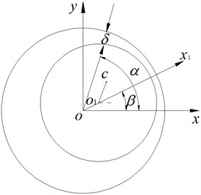
Fig. 1 shows the gap eccentricity of the spindle. The three-phase AC induction motor usually is applied in motorized spindle system, so the energy of the gap magnetic field is [14]:
where the largest component, when , is the dominant factor; other components, when , take different proportions respectively. Because the effective relative eccentricity is much less than 1, take the first three items of the Equation (9):
where: ; ; ; , ; , .
Fig. 1Air-gap eccentricity of the rotor in motorized spindles
Equation (2) can be expressed by:
where ; is the magnetic stiffness matrix of the gap magnetic field:
is the vector of :
At the air-gap units, and must be incorporated into stiffness matrix and generalized force matrix respectively. Therefore the final equations of motion of the spindle-bearing system should be expressed as:
where , and are assembled mass, damping and stiffness matrices respectively, and the parameter matrices (mass, damping and stiffness) of each unit are determined by Timoshenko beam theory [15]; is the bearing stiffness matrix obtained from bearing model [13] and acts at the bearing units.
3. Design flow chart
According to the analysis above, four main DVs can be determined and their definitions are shown in Table 1. These DVs can be separated into two categories, for which DV1 and DV2 belong to bearing location category, while DV3 and DV4 belong to spindle specification category. It should be pointed out that the motor parameter (DV3) presents .
Table 1Design variables (DVs)
DV1 = Spacing between the front and rear bearing sets |
DV2 = Spacing between the front bearing set and the free end of cutter |
DV3 = Motor parameter |
DV4 = Material of the spindle shaft |
Fig. 2 shows the design flow chart of the spindle system. To begin with, bearing dynamic parameters and motor power loss were obtained by solving bearing model and power flow model respectively. Accordingly, the mapped bearing support stiffness based on the bearing configuration model and the UEP can be determined to solve the shaft model. Meanwhile the temperature distribution of the system was obtained with the combination of bearing heat generation, motor heat generation and heat boundary condition, and TDs of the bearing were obtained based on the bearing combination. Then the bearing model and the sub-models coupled with the bearing model are resolved by using the calculated TDs and bearing node displacements to revise the bearing boundary condition. Repeat these steps until the solutions of all sub-models meet an entire convergence precision.
4. Experimental setup
According to the analysis above, we conducted a dynamic design on a 170MD15Y20 type motorized spindle with oil mist lubrication and made the related experiments. Fig. 3 shows the experimental setup. The electric parameters of built-in motor under working conditions can be directly displayed on the operation interface of an automatic test system (IPC-810). The buried thermocouple sensor (PT100) is utilized to measure the temperature of the front bearing pedestal. With the acceleration sensors (B&K4384) we carried out an operational model test [16] to acquire the natural frequencies of the system. The measured signals were amplified by a B&K2692-014 type charge amplifier and then were collected and analyzed by a SC305-UTP LMS Data Collector & Analyzer in a PC.
Fig. 2Design flow chart of motorized spindles
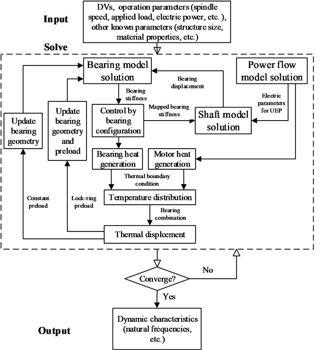
Fig. 3Experimental setup
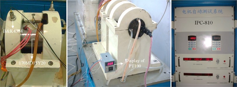
The rated power, voltage, current and frequency are 20 kW, 350 V, 46.3 A and 400 Hz respectively, and the system uses the control method. Both of the two sets of bearings are a pair with series connection and lock-ring preload in bearing configuration. The front and rear bearings are of the types of B7011C and B7009C respectively, and their preloads are 88 N and 40 N respectively, the supplying air pressure is 0.24 MPa and the cooling water flow rate is 1.32 l/min. The elements of the spindle system are shown in Fig. 4, the unit of DV3 is the multiple of motor parameter and DV4 is set to elasticity modulus . Other parameters of the spindle system are listed in Table 2.
Fig. 4Elements of the spindle system
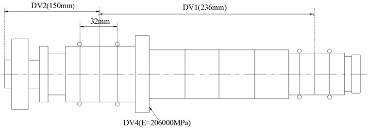
Table 2Parameters of 170MD15Y20 type motorized spindle
Parameter | Units | Given value |
0.11 | ||
0.21 | ||
mm | 1 | |
mm | 40.7 | |
mm | 112 | |
H/mm2 | 1.768×10⁻⁹ | |
° | 68.9 | |
– | 2 |
5. Analysis of results
The validation of the integrated model and the effects of DVs on the first two natural frequencies of the system are presented in this section. To make theoretical computations correspond with the actual use conditions, the sensitivities of DVs to the nature frequencies are discussed with rated speed (12000 rpm).
Fig. 5 shows the first two natural frequencies with various rotational speeds. Because of the position constraint of the bearings, the most of the relative displacement of the inner and outer rings will change to stress in work conditions, which gives rise to additional preload on the bearings. The additional preload can improve the stability of the spindle system, which redeems the decrease of the natural frequencies caused by high speed inertial effects. Therefore the first two natural frequencies increase slightly with the spindle speed. Considering the influence of TD, the bearing expansions lead to the growth of the contact stress between the balls and the inner and outer rings, so the natural frequencies increase. The UEP has little influence on the bearing stiffness, while it has a large influence on the natural frequencies because the magnetic stiffness will reduce the stability of the spindle system. The difference between the coupled calculations (with TD and UEF) and the experimental results in different speeds are within 1.2 %, which testifies to the accuracy of the proposed integrated model.
Fig. 6 shows that the steady-state temperature of the front bearing pedestal increases with the spindle speed. The TD and UEP make the load on the bearing increase, resulting in heightened friction, so the temperature rises when considering the TD and UEP. The good agreement between the coupled calculations (with TD and UEF) and the experimental data further confirms the accuracy of the proposed integrated model.
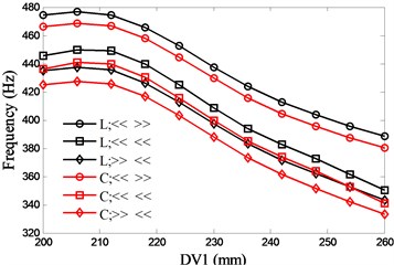
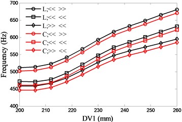
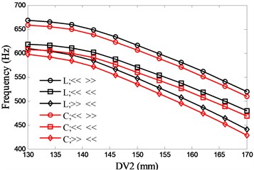
The most common bearing combinations are face-to-face (<< >>), series connection (<< <<) and back-to-back (>> <<). With the two preload methods (lock-ring and constant), six types of bearing configurations are presented. Fig. 7 and Fig. 8 show the influences of DV1 and DV2 on the natural frequencies respectively. With the consideration of the structure size of the discussed spindle, the variations of the DVs are 200 mm to 260 mm (DV1) and 130 mm to 170 mm (DV2) respectively. There is an optimal value (207mm) for DV1 to the first natural frequency and the frequency decreases rapidly when the value of DV1 exceeds the optimal value, while the second natural frequency increases with DV1. With regard to the second natural frequency, the back-to-back bearing combination holds a minor up trend. Both of the first two natural frequencies decrease with DV2 and the series connection of bearing has the most rapid decline in the first natural frequency.
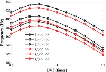
For DV3, and keep the same variation and remains constant, so the diameters of the spindle shaft also change with . Fig. 9 shows the influence of DV3 on the natural frequencies. As seen in the figure, the optimal values of DV3 for the first two natural frequencies are 0.76 (1st) and 0.99 (2nd) respectively.
DV4 denotes the material of the spindle shaft, where only the modulus of elasticity is considered in this work. The influence of DV4 on the natural frequencies is shown in Fig. 10. From the figure it can be known that the first two natural frequencies increase with DV4. Therefore high-strength materials are preferred for high speed motorized spindles.
Fig. 5First two natural frequencies of the system due to changes in spindle speed
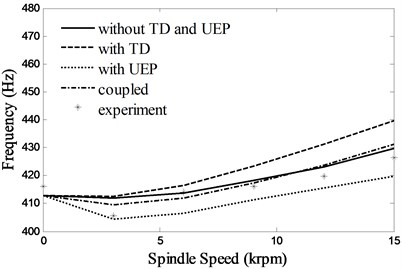
a) 1st
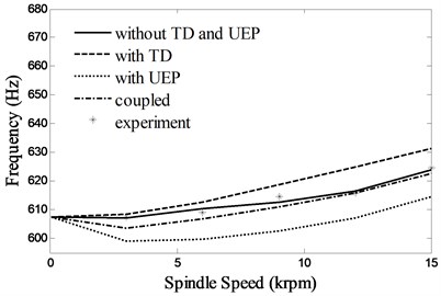
b) 2nd
Fig. 6Steady-state temperatures at the front bearing pedestal
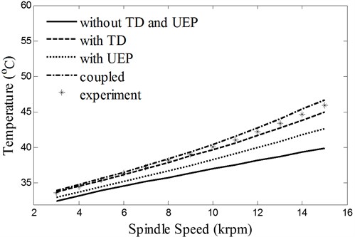
Fig. 7Effects of spacing between the front and rear bearing sets (DV1) on spindle system natural frequencies
a) 1st
b) 2nd
Fig. 8Effects of spacing between the front bearing set and the free end of cutter (DV2) on spindle system natural frequencies
a) 1st
b) 2nd
Fig. 9Effects of motor parameter (DV3) on spindle system natural frequencies
a) 1st

b) 2nd
Fig. 10Effects of material of the spindle shaft (DV4) on spindle system natural frequencies
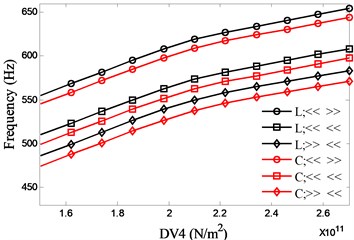
a) 1st
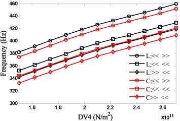
b) 2nd
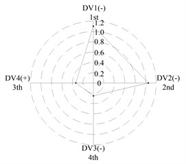
The effects of the four DVs on system natural frequencies have been presented individually above. In the following discussion the maximum and minimum values of the first two natural frequencies and their corresponding values of DVs are identified from the figures above for all four DVs with various bearing configurations and then the differences of the extreme values for each DV are transformed into ratios to their initial values. Dividing the ratios of the first two natural frequencies by the corresponding ratios of DVs and taking their absolute values, an index similar to elasticity measurements could be obtained, which can be used in the relative importance comparison. For example in Figure 10 the minimum and maximum values of the first frequency with bearing face-to-face combination and lock-ring preload (L; << >>) can be found as 382.7 Hz at DV4 = 150 GPa and 459.5 Hz at DV4 = 270 GPa. The differences between these two extreme values of the first frequency and the corresponding values of DV4 can be calculated as 76.8 Hz and 120 GPa, which can be further transformed into ratios of their initial values as 0.1812 for the first frequency and 0.5825 for DV1, respectively. Finally 0.311 is acquired by dividing 0.1812 with 0.5825 and this means that if the variation ratio of DV4 reaches 1, the first frequency will vary with a ratio 0.311 of its initial values correspondingly.
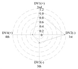
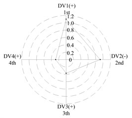
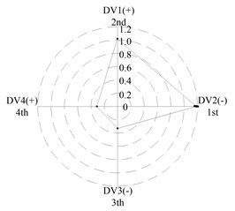
After applying the same procedure to all DVs, the consequent indices are illustrated with radar charts to present the relative importance comparison of the DVs. Figures 11 and 12 show the results for the first two natural frequencies respectively. The sign used in the two figures is designed to represent the tendency. For example in Figure 11 sign DV1(-) means that increases of DV1 will cause the first frequency to decrease, DV4(+) means that increases of DV1 will increase the first frequency. As seen in the figures, if the first natural frequency is determined as the design target, spacing between the front and rear bearing sets (DV1) is the most important design variable, and spacing between the front bearing set and the free end of cutter (DV2), motor parameter (DV3) and material of the spindle shaft (DV4) are second, fourth and third in the DVs. With respect to the second natural frequency, the ranks of DV3 and DV4 exchange, and when the spindle is assembled with bearing back-to-back combination, spacing between the front bearing set and the free end of cutter (DV2) is the most important design variable. Therefore bearing configuration should be considered when conducting a dynamic design for motorized spindles.
Fig. 11Radar charts for the first natural frequency
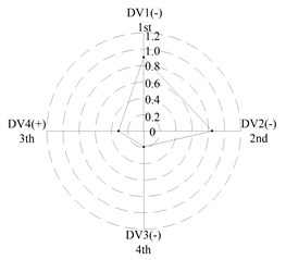
a) L; << >>
b) L; << <<

c) L; >> <<
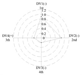
d) L; << >>

e) L; << <<

f) L; >> <<
Fig. 12Radar charts for the second natural frequency
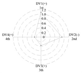
a) L; << >>

b) L; << <<
c) L; >> <<
d) L; << >>

e) L; << <<
f) L; >> <<
6. Conclusions
An integrated model is developed and validated experimentally to predict the multi-physics coupling dynamic behaviors of high speed motorized spindles, and the sensitivities of four main DVs to the nature frequencies are put forward to instruct the dynamic design of the system. According to the results, the following conclusions are obtained:
(a) The proposed integrated model is accurate and robust, which can effectively analyze the electro-thermo-mechanical dynamic performances of high speed motorized spindles and the coupled relationships between them.
(b) TD can slightly increase the natural frequencies of the spindle system with lock-ring preload, but the excessive temperature caused by TD will decrease the useful life of the spindle. The “magnetic stiffness” of UEP will reduce the stability of the spindle system.
(c) For the first natural frequency the vital design variables include spacing between the front and rear bearing sets (DV1) and spacing between the front bearing set and the free end of cutter (DV2), the less important design variables include motor parameter (DV3) and material of the spindle shaft (DV4). To the second natural frequency, the ranks of DV3 and DV4 are inverted, and spacing between the front bearing set and the free end of cutter (DV2) is the most important design variable when the bearings are installed with back-to-back combination.
References
-
Senkus A., Jotautiene E. Investigation of vibro-acoustic properties of modern lathe collet chuck. Journal of Vibroengineering, Vol. 14, Issue 3, 2012, p. 1227-1232.
-
Al-Shareef K. J. H., Brandon J. A. On the effects of variations in the design parameters on the dynamic performance of machine-tool spindle-bearing systems. The International Journal of Advanced Manufacturing Technology, Vol. 30, Issue 3, 1990, p. 431-445.
-
Kang Y., Chang Y. P., Tsai J. W., Chen S. C., Yang L. K. Integrated ‘CAE’ strategies for the design of machine tool spindle-bearing systems. Finite Elements in Analysis and Design, Vol. 37, 2001, p. 485-511.
-
Bossmanns B., Tu J. F. Thermal model for high speed motorized spindles. International Journal of Machine Tools & Manufacture, Vol. 39, Issue 9, 1999, p. 1345-1366.
-
Bossmanns B., Tu J. F. A power flow model for high speed motorized spindles – heat generation characterization. Journal of Manufacturing Science and Engineering – Transactions of the ASME, Vol. 123, Issue 3, 2001, p. 494-505.
-
Lin C. W., Tu J. F., Kamman J. An integrated thermo-mechanical-dynamic model to characterize motorized machine tool spindles during very high speed rotation. International Journal of Machine Tools & Manufacture, Vol. 43, Issue 10, 2003, p. 1035-1150.
-
Lin C. W., Lin Y. K., Chu C. H. Dynamic models and design of spindle-bearing system of machine tools: a review. International Journal Precision Engineering Manufacturing, Vol. 14, Issue 3, 2013, p. 513-521.
-
Jiang S. Y., Zheng S. F. Dynamic design of a high-speed motorized spindle-bearing system. Journal of Mechanical Design, Vol. 132, Issue 3, 2010, p. 0345011-0345015.
-
Jiang S. Y., Zheng S. F. A modeling approach for analysis and improvement of spindle-drawbar-bearing assembly dynamics. International Journal of Machine Tools & Manufacture, Vol. 50, Issue 1, 2010, p. 131-142.
-
Jiang S. Y., Mao H. B. Investigation of variable optimum preload for a machine tool spindle. International Journal of Machine Tools & Manufacture, Vol. 50, Issue 1, 2010, p. 19-28.
-
Li H. Q., Shin Y. C. Analysis of bearing configuration effects on high speed spindles using an integrated dynamic thermo-mechanical spindle model. International Journal of Machine Tools & Manufacture, Vol. 44, 2004, p. 347-364.
-
Chen X. A., Liu J. F., He Y., Zhou J. M., Zhou M. H. A thermal analyzing model for high speed motorized spindles – thermal properties. Advanced Sciece Letters, Vol. 9, Issue 1, 2012, p. 767-772.
-
Jorgensen B. R., Shin Y. C. Dynamics of machine tool spindle/bearing systems under thermal growth. Journal of Tribology – Transaction of the ASME, Vol. 119, Issue 4, 1997, p. 875-882.
-
Qiu J. J. Electromechanical Analysis of Dynamics. Science Press, BeiJing, 1992, p. 513-514.
-
Cao H. R., Holkup T., Altintas Y. A comparative study on the dynamics of high speed spindles with respect to different preload mechanisms. The International Journal of Advanced Manufacturing Technology, Vol. 57, Issue 9-12, 2011, p. 871-883.
-
Chen F., Chen X. A., Meng J. The operational modal test analysis of high speed motorized spindle. Modern Manufacturing Engineering, Issue 8, 2008, p. 14.
About this article

This work is financially supported by National Natural Science Foundation of China (No. 51005259).
