Abstract
Landing gear shock strut binding problem occurred during an unmanned aircraft’s flying test. The half-axle main landing gear of the unmanned aircraft was chosen to analyze the influences of shock strut flexibility on drop dynamics. The friction force was modeled based on the half-axle configuration and taking shock strut flexibility into account. Drop dynamic performances were analyzed and compared with those came from rigid strut model and drop test. Good correlation has been established between drop test data and the simulation predicated results. The results also showed that though the total axis force added merely 1 % when taking shock strut flexibility into account, the friction force added almost 45 %. A comprehensive deformation compatibility factor was presented to describe the actual deformation of shock strut bearings. Influence of deformation compatibility factor, flexibility of inner and outer cylinder were studied further.
1. Introduction
There are four fundamental force elements, (air spring force, hydraulic force, friction force and structural limit force), in landing gear drop dynamic modeling usually [1]. For researches focus on whole aircraft or control performance, friction force is neglected or simplified frequently. In David H. Chester’s research on aircraft landing dynamics with emphasis on nose gear landing conditions [2], Phil Evans’s research on tricycle landing gear landing dynamics at normal and abnormal conditions [3], and David C. Batterbee’s research on magneto rheological oleo pneumatic landing gear drop dynamics [4], friction force of the shock strut were neglected. Anthony G. Gerardi’s landing gear model included friction force at first. However, the friction force was neglected when taking the symmetrical configuration of landing gear wheels into account [5]. Gu Hongbin simplified shock strut hydraulic damping and friction damping as a linear damping [6] and Yuan dong simplified them as a nonlinear damping [7]. Kapseong Ro [8],Jia Yuhong [9], Mu Rangke [10] mentioned that friction force were concluded in their dynamic models, but the friction force model were not presented in the articles.
For landing gear drop dynamics, friction force is usually taken into account. In Benjamin Milwitzky’s landing gear drop dynamic model [11], shock strut outer cylinder and inner cylinder were assumed as rigid. Shock strut friction force was modeled as the function of reaction forces at upper bearing and lower bearing. Francis E. Cook adopted the same friction force modeling method as Benjamin Milwitzky’s work [12]. Mahinder K. Wahi [13] and Wei Xiaohui [14, 15] inherited this model in their landing gear and aircraft landing dynamics.
Prashant Dilip Khapane neglected structural friction force and modeled the shock strut friction force as the function of inner air pressure, namely seal friction [16]. In fact, the more practical method is to add this seal friction force to structural friction force. James N. Daniels adopted this friction force model [17], and Archie B. Clark [18], Nie Hong [1], and Sui Fucheng [19] inherited this model in their researches respectively.
With the use of high-strength steel, such as 300M steel [20] and A100 steel [21], aircraft landing gear became more and more flexible. It seemed imperative that if the conventional rigid shock strut assumption still suitable for landing gear drop dynamics should be studied.
Frictional damping of the landing gear shock strut should be as small as possible, and it is usually no more than 5 percent of the shock strut axial force [22]. Shi Haiwen mentioned that tire longitudinal force has a great influence on the shock strut friction force [23]. But for the half-axle landing gear, tire vertical force also has an adverse effect on the shock strut friction force.
The shock strut of half-axle landing gear suffered more bending moment than the landing gear with symmetric layout of wheels. If the shock strut is not rigid enough, the influences of shock strut bending are non-ignorable. Gao Zejiong presented that the shock strut’s bending deformation would add an additional moment on the bearings between inner and outer cylinder [22]. That would make the friction characteristic of the shock strut worse and possibly led to binding problem. But there are not any published researches of the effect of shock strut flexibility on the shock strut friction force and drop dynamics of landing gear. Then, the half-axle main landing gear of the aircraft was chosen to analyze the influences of shock strut flexibility on the shock strut friction force and drop dynamics.
2. Landing gear configuration and forces
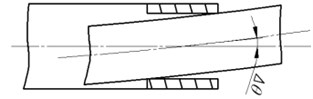
The structural configuration of the main landing gear of the unmanned aircraft is a kind of half-axle shock strut. Figure 1 shows a schematic representation of the landing gear configuration. Figure 2 shows the forces on wheel and inner strut.
The ground coordinate system is fixed to the ground. The origin is a point located on the ground, axis is in the forward longitudinal direction, axis is in the upward direction, axis is followed the right-hand rule.
Fig. 1Landing gear configuration
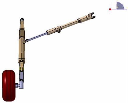
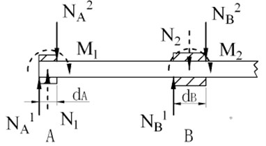
Fig. 2Forces on wheel and inner strut
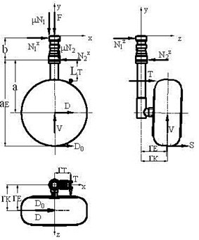
In Figure 2: is the friction coefficient of bearings, is the displacement between wheel axle and lower bearing, is the displacement between lower bearing and upper bearing, is the displacement between pivot point of torque arm and lower bearing, is the displacement between the center of wheel axle and shock strut axis, is the displacement between the line of torque arm action force and shock strut axis, and is the longitudinal and vertical ground reaction force respectively, and is the upper bearing reaction force in plane and plane respectively, and is the lower bearing reaction force in plane and plane respectively, and is the longitudinal and vertical wheel axle force respectively, is the torque arm action force.
3. Drop dynamic model
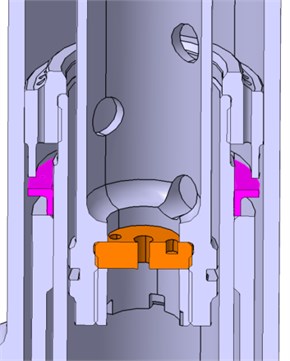
The basic equations of motions are those used for a two-degree-of freedom system as shown in Figure 3. Figure 4 shows the schematic representation of the land gear’s oleo-pneumatic shock strut.
Fig. 3System with two degrees of freedom
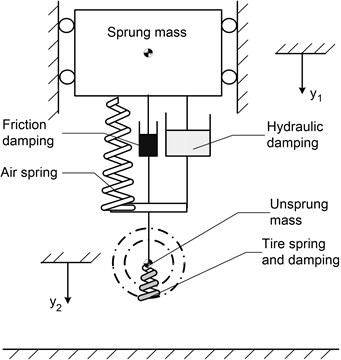
Fig. 4Schematic representation of shock strut
Equations of motion, tire forces and shock strut forces are modeled according to Nie’s research [1].
Equation of motions can be expressed by:
where and is the sprung and unsprung mass respectively, is pneumatic force, is hydraulic force, is friction force.
Equations of motion, tire forces and shock strut forces are the same as Nie’s research, except that shock strut friction force is modeled as follow.
Friction in this gear comes mainly from two sources, friction due to tightness of the seal and friction due to the forces on tire(moment), and can be expressed by:
where is shock strut friction force, is seal friction force and is friction force due to the forces on tire.
The seal friction is assumed to be a function of internal air pressure and can be expressed by:
where is the friction coefficient of seal cup, is the shock strut air spring force.
The friction due to the forces on tire is the result of the moment produced by the nonaxially loaded piston within the cylinder. Considering flexibility of the shock strut, Figure 5 shows the forces in plane, then:
where is the displicement between ground and lower bearing, is the displacement between upper bearing and the end of outer cylinder, is the side ground reaction force, and is the bending moment due to shock strut flexibility at upper and lower bearing in plane respectively.
Fig. 5Forces in Oyz plane
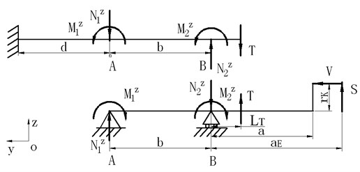
Fig. 6Forces in Oxy plane
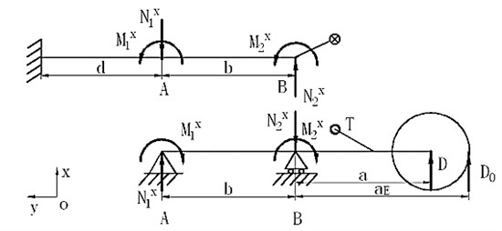
Figure 6 shows the forces in the plane, then:
where and is the bending moment due to shock strut flexibility at upper and lower bearing in plane respectively.
Assuming that the deformation of outer cylinder and inner cylinder at upper and lower bearings is compatible, ideal situation is shown in Figure 7.
Fig. 7Ideal deformation compatibility
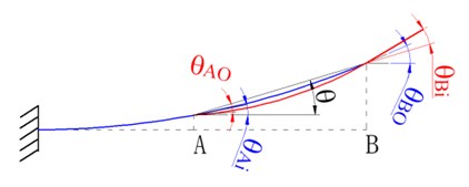
Then, the equation of deformation compatibility can be derived as:
where and is the deformation angle of outer cylinder at upper and lower bearing respectively, and is the deformation angle of inner cylinder at upper and lower bearing respectively, is the angle between the line connecting and before and after the deformation.
In fact, there is a slight deflection angle due to bearing deflection or fit clearance as shown in Figure 8.
Fig. 8Actual deformation compatibility
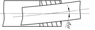
(a)
(b)
Then Eq. (9) and (10) can be revised as:
where and is the slight deflection angle due to bearing deflection or fit clearance at upper and lower bearing respectively.
and are affected by many factors. This paper presents a comprehensive deformation compatibility factor to describle actual deformation. The value of can be obtained from special test.
Then the total bending moment and reaction force at upper and lower bearing can be expressed as:
where and is the total bending moment at upper and lower bearing respectively, and is the total reaction force at upper and lower bearing respectively.
In order to calculate the equivalent reaction force, the forces at upper and lower bearing can be model as Figure 9.
Fig. 9Equivalent forces
According to Figure 9, then:
where and is the width of upper and lower bearing respectively, and is the equivalent reaction force at upper bearing, and is the equivalent reaction force at lower bearing.
Then, the total reaction force of bearings when taking shock strut flexibility into account can be expressed by:
where is the total reaction force of bearings.
Then, the total friction force due to the forces on tire can be expressed by:
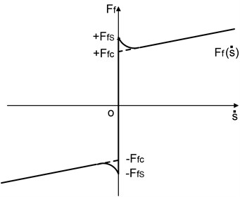
Friction model can be expressed [24] by:
where is the sum of outer forces, is shown as Figure 10.
Fig. 10Schematic diagram of friction model
4. Numerical calculation and analysis
Parameters of the landing gear used in the analysis are list in Table 1.
Table 1Parameters of the landing gear
Parameters | Value | Parameters | Value | Parameters | Value | Parameters | Value |
/ kg | 692.5 | / m | 0.352 | / m | 0.542 | 0.06 | |
/ kg | 15 | / m | 0.134 | / m | 0.126 | 0.3 | |
/ (m/s) | 2.34 | / m | 0.266 | 0.025 | / m | 0.19 | |
/ (m/s) | 36.7 | / m | 0.165 | / m | 0.127 | 0.2 |
In Table 1, is the sink speed of the landing gear, is the longitudinal speed of the landing gear, is the friction coefficient between tire and ground, is the tire radius, subscript 0 stands for the value at initial time.
According to the drop dynamic model constructed above, an analysis program based C++ was developed to calculate the dynamical response of the landing gear during drop process. The results are shown as Figure 11, Figure 12 and Table 2.
Fig. 11Time history of shock strut axis force
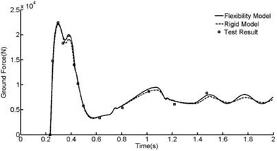
Fig. 12Time history of friction force

Drop dynamic performances came from rigid strut model were presented in Figure 11, Figure 12 and Table 2 in addition.
Table 2Comparison of numerical calculated and test results
/ N | / N | / N | / N | |||
Test results | / | 22400 | 6630 | / | 3.30 | |
Rigid strut model | Calculated results | 21643 | 22038 | 6611 | 3296 | 3.25 |
Relative error | / | –1.6 % | –0.2 % | / | –1.6 % | |
Flexibility strut model | Calculated results | 21855 | 22245 | 6674 | 4764 | 3.28 |
Relative error | / | –0.6 % | 0.5 % | / | –0.6 % | |
In Table 2, is the total axis force of the shock strut, subscript stands for the maximum value.
According to Figure 11 and Table 2, good correlation has been established between drop test data and the simulation predicated results. Compared with the rigid model, the total axis force added merely 1 % when taking shock strut flexibility into account. Though shock strut flexibility has a tiny influence on shock strut axis force, the friction force added enormously according to Figure 12 and Table 2. The friction force added almost 45 % when taking shock strut flexibility into account. Shock strut friction force is the main factor that leads to shock strut binding problem.
Comprehensive deformation compatibility factor have a great influence on shock strut friction force according to Eq. (11) and Eq. (12). In order to learn how will this comprehensive deformation compatibility factor affects shock strut friction force, comparisons were presented in Figure 13 and Table 3.
Fig. 13Effect of deformation compatibility factor
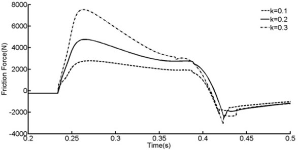
Table 3Comparison of deformation compatibility factor
0.2 | 0.1 | 0.3 | |
Relative variation | / | –50 % | 50 % |
Max friction force | 4764 | 2777 | 7529 |
Relative variation | / | –41.7 % | 58.0 % |
According to Figure 13 and Table 3, shock strut fricton force will decrease 41.7 % when deformation compatibility factor equals 0.1, and will increase 58.0 % when deformation compatibility factor equals 0.3. Shock strut fricton force vary almost linearly with comprehensive deformation compatibility factor.
In order to learn how will shock strut flexibility affects shock strut friction force, comparisons were presented in Figure 14, Figure 15 and Table 4.
According to Figure 14, Figure 15 and Table 4, shock strut friction force will be increased with the increasing of the flexibility of outer cylinder or decreasing the flexibility of inner cylinder. 30 % decreasing of the flexibility of inner cylinder leads to 15.1 % increasing of shock strut friction force.
Fig. 14Effect of the flexibility of outer cylinder
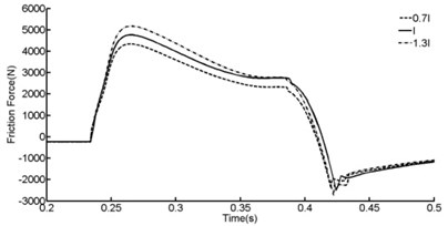
Fig. 15Effect of the flexibility of inner cylinder
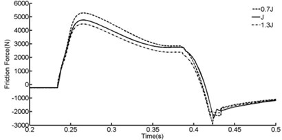
Table 4Comparison of shock strut flexibility
Flexibility of outer cylinder | Flexibility of inner cylinder | ||||
Relative variation | / | –30 % | 30 % | –30 % | 30 % |
Max friction force | 4764 | 4339 | 5170 | 5284 | 4671 |
Relative variation | / | –8.9 % | 8.5 % | 15.1 % | –2.0 % |
5. Conclusions
(1) Shock strut flexibility has a tiny influence on the total shock strut axis force during drop process. However, it has a enormous influence on shock strut friction force. Though the total axis force added merely 1 % when taking shock strut flexibility into account, the friction force added almost 45 %.
(2) Comprehensive deformation compatibility factor has a great influence on shock strut friction force. Shock strut fricton force vary almost linearly with Comprehensive deformation compatibility factor.
(3) Increasing the flexibility of outer cylinder or decreasing the flexibility of inner cylinder will increase the shock strut friction force. In order to eliminate the binding problem of this landing gear, the relative flexibility of outer cylinder and inner cylinder should be decreased suitably.
References
-
Nie H. Dynamic behavior analysis and design as well as life prediction method of landing gear. Nanjing (NJ): Nanjing University of Aeronautics and Astronautics, 1990, (in Chinese).
-
David H. C. Aircraft landing impact parametric study with emphasis on nose gear landing conditions. Journal of Aircraft, Vol. 3, Issue 39, 2002, p. 394-403.
-
Phil E., Mario G., Perhinschi, Steven M. Modeling and simulation of a tricycle landing gear at normal and abnormal conditions. AIAA Modeling and Simulation Technologies Conference, Toronto, Canada, 2010.
-
David C. B., Neil D. S., Roger S., Zbigniew W. Design and performance optimization of magneto rheological oleo pneumatic landing gear. Smart Structures and Materials 2005: Damping and Isolation, Proceedings of SPIE, Bellingham, WA, 2005, p. 77-88.
-
Anthony G. G. Digital simulation of flexible aircraft response to symmetrical and asymmetrical runway roughness. AFFDL-TR-77-37, 1977.
-
Gu H B. Dynamic model of aircraft ground handling. Acta Aeronautica et Astronautica Sinica, Vol. 22, Issue 2, 2001, p. 163-167, (in Chinese).
-
Yuan D. Establishment method of a landing gear simulation model. Flight dynamics, Vol. 20, Issue 4, 2002, p. 44-47, (in Chinese).
-
Kapseong R. A Descriptive modeling and simulation of aircraft-runway dynamics. 44th AIAA/ASME/ASCE/AHS Structures, Structural Dynamics and Materials Conference, Norfolk, Virginia, 2003.
-
Jia Y. H., He Q. Z., Yang G. Z. Taxiing performance analysis of active control of landing gear. Acta Aeronautica et Astronautica Sinica, Vol. 20, Issue 6, 1999, p. 545-548, (in Chinese).
-
Mu R. K., Luo J. J. Effect of aircraft structure flexibility on the shock-absorber behavior of landing gears. Acta Aeronautica et Astronautica Sinica, Vol. 16, Issue 2, 1995, p. 205-208, (in Chinese).
-
Benjamin M., Francis E. C. Analysis of landing-gear behavior. NACA Report 1154, 1953.
-
Francis E. C., Benjamin M. Effect of interaction on landing-gear behavior and dynamic loads in a flexible airplane structure. NACA Report 1278, 1955.
-
Mahinder K. W. Oleopneumatic shock strut dynamic analysis and its real-time simulation. Journal of Aircraft, Vol. 4, Issue 13, 1976, p. 303-308.
-
Wei X. H., Nie H. Dynamic analysis of aircraft landing impact using landing-region-based model. Journal of Aircraft, Vol. 42, Issue 6, 2005, p. 1631-1637.
-
Wei X. H., Ben L. L., Nie H., Zhang M. Analysis of the anti-vibration holdback device of carrier-based aircraft. Journal of Nanjing University of Aeronautics &Astronautics, Vol. 45, Issue 1, 2013, p. 1-7, (in Chinese).
-
Prashant D. K. Simulation of asymmetric landing and typical ground maneuvers for large transport aircraft. Aerospace Science and Technology, Vol. 7, 2003, p. 611-619.
-
James N. Daniels A method for landing gear modeling and simulation with experimental validation. NASA Contractor Report 201601, 1976.
-
Archie B. C. An investigation of classical dynamic scaling techniques applied to an oleo-pneumatic landing gear strut. AFWAL-TR-86-3058, 1987.
-
Sui F. C., Lu H. Mathematical model research on aircraft landing gear damper. Aircraft design, Vol. 2, 2001, p. 44-51, (in Chinese).
-
Peng W. W., Zeng W. D., Kang C., Jia Z. Q. Effect of heat treatment on microstructure and properties of 300M ultrahigh strength steel. Transactions of materials and heat treatment, Vol. 33, Issue 3, 2012, p. 94-98, (in Chinese).
-
Zhong P. Microstructure and mechanical properties in A-100 ultrahigh strength steel. Proceedings of Chinese iron and steel annul meeting, Metallurgical Industry Press, Beijing, 2001, p. 825-828, (in Chinese).
-
Gao Z. J. Aircraft design manual: takeoff and landing system design. Aviation Industry Press, Beijing, 2002, (in Chinese).
-
Shi H. W. A research in shock parameters of rock arm landing gear and telescopic landing gear. Acta Aeronautica et Astronautica Sinica, Vol. 8, Issue 12, 1987, p. B625-B629, (in Chinese).
-
Liu L. L., Liu H. Z., Wu Z. Y., et al. An overview of friction models in mechanical systems. Advances in Mechanics, Vol. 38, Issue 2, 2008, p. 201-211, (in Chinese).
About this article

This study was co-supported by the National Natural Science Foundation of China (Grant Nos: 51105197 and 51075203) and the Priority Academic Program Development of Jiangsu Higher Education Institutions.
