Abstract
Inerter is an additional suspension element to spring and damper with the property that the force generated is proportional to the relative acceleration between its two terminals. This study investigates the effectiveness of a parallel inerter in various vehicle suspension systems to provide superior vibration isolation. In the study, the inerter was paired in parallel to passive, semi-active and active vehicle suspension systems, and the systems were solved with a quarter vehicle model to obtain suspension responses due to ground excitations in the form of step and random road profiles. From the analysis, it was observed that inerter force and spring force were anti-phase to each other, and in parallel layout the cancellation of the two forces gave better vibration isolation to a sprung mass. This provided superior ride performance in vehicle suspension application as indicated by the reduction in vertical sprung mass acceleration. It was also found that the effectiveness brought by parallel inerter was independent on the various vehicle suspension systems; however, the improvement was only slight as the cancellation of forces was insignificant relative to the damping force associated with the specific vehicle model used in the study.
1. Introduction
In its basic form, a suspension system consists of a spring element which supports static load and a damping element which dissipates system energy to achieve the goal of vibration isolation. Together with the suspended or sprung mass, they form the mass-spring-damper system which is the mechanical analog of the electrical resistor-inductor-capacitor circuit in the well-established force-current analogy [1]. However, the analogy is incomplete as mass is a one-terminal element and is strictly only analogous to a grounded capacitor. This analogy can be made complete by utilizing the rotation of a flywheel to achieve a two-terminal mass [2, 3], which gives rise to an additional suspension element more commonly known as the inerter. Based on its ideal definition, an inerter is a mechanical, two-node, one-port suspension element with the property that the equal and opposite force applied at the nodes is proportional to the relative acceleration between the nodes [4]. This can be stated as Eq. (1):
in which is the equal and opposite force, , are the accelerations of the two terminals and is a proportionality constant, similar to spring stiffness and damping rate, which is termed the inertance. Although inerter stems from the conceptual force-current analogy, it can be easily realized in physical form. The construction of an inerter normally involves a flywheel which is free to rotate and some means, like the rack-and-pinion [4], ball screw [5] and hydraulic [6] mechanisms, to achieve the conversion between rotational motion of flywheel and linear motion due to suspension deflection.
Due to it being a general suspension element, studies have demonstrated the use of inerter in various suspension applications. In general, its use in these applications brings performance benefits when compared to conventional suspension system. For example, in 2004, Evangelou et al. [7] applied the inerter element in motorcycle in the form of a mechanical steering compensator to replace the conventional steering damper, and the study showed that the steering compensator improved the wobble and weave modes of damping experienced in high performance motorcycle. In another application, Wang et al. [8] studied the capability of inerter to improve train suspension using a one-wheel suspension model. From the optimization of suspension based on passenger comfort and dynamic wheel load, it was determined that the presence of inerter improved the former performance index. In the field of structural vibration, there are also studies concerning the implementation of inerter in building suspensions for vibration isolation purpose [9, 10]. These studies investigated the potential benefits of building suspension systems employing inerter using one-degree-of-freedom and two-degree-of-freedom building models that were isolated from a fixed ground through suspensions, and the outcome showed effectiveness of the inerter in suppressing vibration from traffic and earthquakes. In this aspect, the benefits due to an inerter are similar to those brought by a tuned mass damper of which the use in buildings and structures for vibration isolation has been extensively studied [11, 12]. However, it is worth noting that an inerter is a two-terminal suspension element and is ideally massless (similar to spring and damper); this distinguishes it from a mass damper that is one-terminal and adds weight to the overall system, which is undesirable in certain applications such as in passenger vehicle suspensions.
In the specific application of inerter in vehicle suspensions, past researches have generally demonstrated its superior ride performance to conventional suspension with only spring and damper. In 2004, a study by Smith and Wang [13] considered passive vehicle suspensions incorporating inerter in several suspension layouts, including the parallel layout (inerter in parallel to other suspension elements) and the serial layout (inerter in series to another suspension element). Through optimization based on ride comfort, tire load and suspension’s load carrying capability, the study claimed improvements in the performance measures when the measures were independently optimized. In 2009, Scheibe and Smith [14] extended the above study with analytical solutions instead of numerical optimization solutions and further showed that simultaneous improvements in ride comfort and tire load measures were possible for suspensions with inerter. Similarly, study by Li et al. [15] showed that the use of a two-terminal mass in parallel to a passive vehicle suspension brought superior passenger comfort and tire grip with equal suspension deflection performance measure. From these studies, it can be seen that the benefit of implementing an inerter in passive vehicle suspension system is already clear; however, it is observed that the effect of inerter on other types of vehicle suspension systems, such as controllable suspensions, are presently less studied compared to passive suspension.
Therefore, this study intends to investigate the effectiveness of a parallel inerter in providing better vibration isolation when it is used in different vehicle suspension systems, so that its benefit in the vehicle suspension application is more comprehensively known. The study was structured as follows: firstly, the complementary property of an inerter to spring was demonstrated by looking into the dynamics associated with a fundamental spring-inerter suspension setup. Then, the application of parallel inerter in passive vehicle suspension was studied to determine the interaction of suspension component forces under road excitation which justified the ride performance improvement brought by parallel inerter. Finally, the parallel inerter was paired with both passive and controllable suspension systems, and the responses were analyzed to evaluate a parallel inerter’s effectiveness in various types of vehicle suspension systems. These are detailed in Sections 2, 3 and 4 respectively.
2. Inerter as a complementary element to spring
Fundamentally, both inerter and spring are similar elements in a suspension system because they are energy storing elements as opposed to a damper which is an energy dissipater. In an early study of inerter, Smith [4] considered the inerter as a mechanical-dual of spring. However, a difference between the two is that spring reacts to relative displacement while inerter reacts to relative acceleration. Hence, although similar, these two elements actually complement each other in a suspension system. For example, a recent study by Nie et al. [16] highlighted a complementary property in an effort to justify the working principle of a serial inerter. According to the study, spring is good at attenuating high-frequency vibration, while inerter excels at isolating low-frequency vibration. Therefore, a suspension incorporating a spring-damper combination in series to an inerter-damper combination will theoretically attenuate vibration for a wider frequency range [16]. While this rationale is true for the serial inerter layout, it does not justify the performance improvement of suspension with parallel inerter reported in previous studies since a parallel arrangement between spring and inerter, according to the proposed explanation, will worsen the vibration isolation instead. This suggests that there exist other justifications to the effectiveness of a parallel inerter.
One way of explaining the vibration isolating capability of suspension with parallel inerter is through the dynamical reasoning because the suspension performance (for instance, measure of ride comfort for vehicle suspensions) is associated to the acceleration of sprung mass which, in turn, is dependent on the suspension force acting on the sprung mass. To investigate the complementary behavior between spring and inerter from the dynamical point of view, consider a simple suspension setup made up of the two elements with one terminal grounded or fixed and the other subjected to a sinusoidal displacement input as in Fig. 1. Due to the input, forces are generated by both spring and inerter following Eq. (2) and Eq. (3) respectively. The resultant of forces forms the suspension force which is shown in Eq. (4) as below:
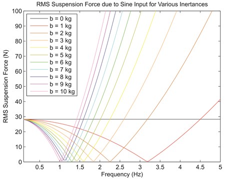
in which , , are the spring, inerter and resultant or suspension forces, is the spring stiffness, is the inertance, , are the displacements at terminals 1 and 2, , are the corresponding accelerations, is the sinusoidal input with amplitude frequency and phase angle . The complementary property between inerter and spring can be seen in Eq. (4). It is known that acceleration is anti-phase to displacement since it is the double derivative of the sinusoidal input. Because inerter reacts to relative acceleration while spring reacts to relative displacement, the forces due to them are also anti-phase to each other. Due to the opposition of forces, the resultant force is lowered, if not eliminated at specific frequency, thus contributing superior vibration isolation to a sprung mass. The force cancellation scenario is illustrated in Fig. 2, which shows that the root-mean-squared (RMS) value of suspension force approaches zero under specific frequencies for stiffness, 400 Nm-1 and inertance, from 0 kg to 10 kg.
Fig. 1Simple suspension setup with spring and inerter in parallel layout
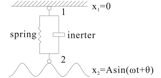
Fig. 2RMS value of suspension force for various frequencies of the sinusoidal input
It is worth noting the resemblance of this situation to resonance experienced by a typical mass-spring-damper system. During resonance, the spring force and the inertial force of the mass eliminate each other, causing large oscillatory motion to the mass only to be limited by damping within the system. Meanwhile, for a suspension setup with parallel inerter, the elimination occurs between spring and inerter forces, leaving a sprung mass undisturbed.
3. Application of parallel inerter in vehicle suspensions
As the dynamical complementary property of a parallel inerter is generally applicable, the interaction between spring and inerter forces may be used to justify the effectiveness of parallel inerter in the specific application in this study, namely vehicle suspension where the performance benefits for passive suspension system have been shown in previous studies [2, 13, 15]. Unlike typical suspension applications, a vehicle suspension not just serves the purpose of isolating the vehicle body from road roughness which brings ride quality, but also ensures tire-road contact with minimal load variation for good road holding ability [17]. This study generally focuses on the evaluation of ride comfort achieved by vehicle suspensions with parallel inerter, which is primarily measured by the RMS sprung mass acceleration when the vehicle is under road excitation. A two-degree-of-freedom quarter vehicle model, consisted of sprung and unsprung masses representing vehicle body and wheel, was employed in the analysis. According to a study by Georgiou et al. [18], this model is commonly used in the prediction of dynamic response as well as the performance of parameter identification, optimization and control studies of ground vehicles. In a related study by Verros et al. [19], it was pointed out that this is mostly due to its simplicity in representing a vehicle and the qualitatively correct information it provides especially for ride and handling studies. The use of mathematical vehicle model is also consistent with earlier studies on inerter element [13, 15, 20].
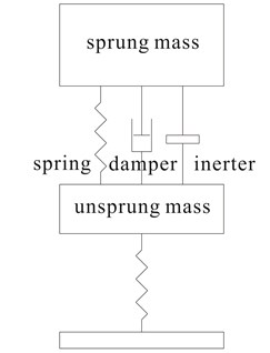
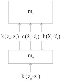
For a parallel suspension layout, the inerter was added in parallel to existing suspension setup comprising of both a spring and a damper which were also parallelly arranged as in most actual vehicle suspensions. This is shown in Fig. 3(a). The system can be conveniently solved to obtain suspension response by solving the equations of motion (Eq. (5) and Eq. (6)) derived from the system’s free-body diagram in Fig. 3(b):
in which , are the sprung and unsprung mass values, are the sprung and unsprung mass displacements, , , , are the corresponding velocities and accelerations, is the vertical road displacement, , , , , are the tire stiffness, spring stiffness, damping rate, and inertance respectively. Since ride was the primary focus in the study, the vehicle parameters in Eq. (5) and Eq. (6) took values that were typical of a passenger vehicle: 317.5 kg, 45.4 kg, 22000 Nm-1, 1500 Nsm-1, 192000 Nm-1 [21], similar to other studies concerning passive [16] and controllable suspension systems [22]. Input to the system came from the vertical road displacement, which had a simple step profile with 0.1 m height in this part of the study. Step input is commonly used in quarter vehicle model analyses as an emulation of the vehicle hitting a curb or an obstacle, and it also allows the sprung and unsprung masses to oscillate at their natural frequencies, namely the body bounce and wheel hop frequencies. The system was solved iteratively for an inertance range (0 kg320 kg) which corresponded to a range from zero to one for the ratio of inertance to sprung mass as adopted in a relevant study [15], and the suspension component forces were evaluated for the case with optimum inertance which was determined based on the objective of minimizing RMS sprung mass acceleration (hence maximizing ride improvement). From the results obtained, the time history of spring, damper and inerter forces due to step input for the optimum case of 6 kg is illustrated in Fig. 4 for further evaluation.
Fig. 3(a) Quarter vehicle model with parallel inerter and (b) its free-body diagram
(a)
(b)
Fig. 4Spring, damper and inerter forces due to step input of 0.1 m for optimum case
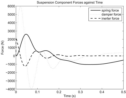
Fig. 4 clearly illustrates the complementary or anti-phase property between spring and inerter. From the dynamical point of view, the opposition between the two suspension component forces resulted in reduced resultant or total suspension force acting on the sprung mass which, in turn, lowered the RMS sprung mass acceleration and led to improvement in ride comfort. This provides a fundamental explanation to the effectiveness of a parallelly-arranged inerter in providing better vibration isolation, or better ride performance in terms of vehicle suspension application. However, although effective, the RMS sprung mass acceleration result from the analysis showed only slight decrease from 2.0046 ms-2 (reference case, 0 kg) to 1.9640 ms-2 (optimum case, 6 kg) which was insignificant (2.03 %), when the parallel inerter was treated as an ‘add-on’ device to existing spring and damper using existing suspension parameters. This is mainly because of the unsuitably high damping rate used in the study which generated high damping force (Fig. 4). Considering that total suspension force in parallel suspension layout is the resultant of all component forces, the decrease in resultant force due to spring-inerter force cancellation becomes insignificant relative to the high damping force, inferring that both damping rate and inertance need to be optimized in a suspension employing parallel inerter.
4. Effectiveness of parallel inerter in controllable suspension systems
From the preceding section, it is already known that the effectiveness of a parallel inerter in achieving better ride comfort is due to the opposition and cancellation between inerter and spring forces which reduces the RMS sprung mass acceleration. As the benefit of a parallel inerter to passive vehicle suspension has been justified dynamically, it is then interesting to investigate further the interaction between an inerter and controllable vehicle suspension systems instead, since a controllable suspension system is also capable of providing superior ride performance, and there is a possibility that simultaneous implementation of the two will bring even greater ride improvement. In the study, the inerter was again considered as an add-on element and was employed in parallel to several well-established controllable suspension systems that were adopted from literature [21], which replaced the passive suspension used in the preceding section. These systems included a semi-active two-state switchable damper (TSS) using discrete, two-state Skyhook control strategy, a semi-active continuously variable damper (CVD) and an active suspension using control strategies based on linear optimal control method. The relevant control strategies are stated as Eq. (7), Eq. (8) and Eq. (9) respectively:
in which , , , , , and are the same variables as defined previously, , are the maximum and minimum damping rates in a two-state switchable damper (1500 Nsm-1 and 900 Nsm-1 in this study), is the damper force, is the required control force to be provided by a damper or an actuator, while and are the sets of feedback gains that were determined based on a previous study on linear optimal control theory [23].
For the study, the various vehicle suspension systems, together with the parallel inerter, were incorporated in the same mathematical vehicle model as employed in the preceding section for consistency. However, in the analysis, two types of road profiles were considered as the road input to the system. While the step profile with 0.1 m step height was the same as used earlier, another input, namely the random road profile, was also considered to emulate ground excitation experienced by a vehicle due to normal driving conditions. This ensured closeness of simulations to the reality since a typical road is generally characterized by the presence of large isolated irregularities such as potholes and curbs in combination with continuously distributed profile irregularities [19]. Random road profiles are typically represented in the form of spectral density curves. Generally, the spectral density curves can be mathematically represented as Eq. (10):
in which is the density in the unit of m2(cycle.m-1)-1, is the spatial frequency in cycle.m-1 which is related to frequency in Hz by multiplying with the velocity of travel in ms-1 (20 ms-1 in this study to emulate regular driving condition), 0.1 cycle.m-1 is the reference frequency as used in a similar study [24], is a non-dimensional index (2 in this study), and is the roughness coefficient in m2(cycle.m-1)-1. According to ISO 8608: 1995 [25], road profiles can be classified into several classes with different roughness coefficients, for instance as shown in Table 1. From this data, a single track can be generated by adding together a discrete number of sine waves; the amplitudes are derived from spectral density data, while the phase angles are determined through a random number generator [21]. In this part of the analysis, three different roughness coefficients (representing three road classes), namely class A (smooth), class C (average) and class E (poor) were considered for completeness of the study.
Table 1Classification of road profiles
Road classification | Range (×10-6 m2(cycle.m-1)-1) | Geometric mean (×10-6 m2(cycle.m-1)-1) |
A (very good) | < 8 | 4 |
B (good) | 8 – 32 | 16 |
C (average) | 32 – 128 | 64 |
D (poor) | 128 – 512 | 256 |
E (very poor) | 512 – 2048 | 1024 |
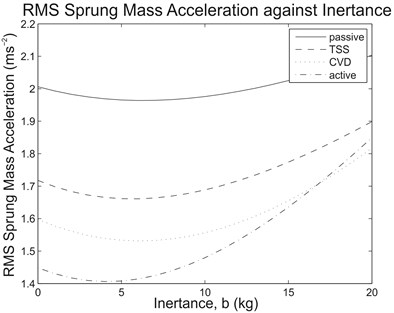
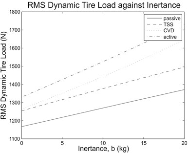
With these road inputs, the mathematical vehicle model consisting of the semi-active and active suspension systems was solved with the same test range for inertance (0 kg320 kg) to determine the suspension performance measures, and the potential benefit of a parallel inerter on the controllable suspension systems was then evaluated. As an overview of the results, Fig. 5 illustrates the RMS sprung mass acceleration and RMS dynamic tire load against the inertance range of interest due to step input, while Table 2 outlines the comparison of RMS sprung mass acceleration between the reference case (0 kg) and the cases with optimum inertance for various controllable suspension systems. For comparison purpose, results for the case with passive suspension system are also presented.
As can be observed from Fig. 5(a), for each of the tested vehicle suspension systems subjected to step input, there was a reduction in the RMS sprung mass acceleration when the optimum inertance was used. Basically, this inferred that the effectiveness brought by a parallel inerter to vehicle suspensions was independent on the types of suspension system. Clearly, for passive and semi-active vehicle suspension systems, the inerter force only opposed the spring force; therefore, the cancellation of forces existed regardless of the types of damper used in the suspensions. Meanwhile, for the specific active suspension system employed in the study, although the system involves the use of an actuator to replace the spring and damper combination altogether, the control strategy as stated in Eq. (10) actually consists of an implicit spring force term which can be shown by rearranging the equation. Hence, the parallel inerter also demonstrated ride improvement for the tested active suspension system. However, it was also noticed from Fig. 5(b) that the RMS dynamic tire load increased for all types of vehicle suspension system along with inertance within the range of interest. This indicated reduced tire road holding ability due to increased tire load variation and became a compromise in an effort to minimize sprung mass movement.
Fig. 5(a) RMS sprung mass acceleration and (b) RMS dynamic tire load against inertance range of interest due to step input for the tested suspension systems
(a)
(b)
Table 2Comparison of RMS sprung mass accelerations for the tested suspension systems
Suspension system | RMS sprung mass acceleration (ms-2) | Difference (%) | |
Reference (0 kg) | With optimum inertance | ||
Step input | |||
Passive | 2.0046 | 1.9640 (6 kg) | –2.03 |
TSS | 1.7176 | 1.6610 (6 kg) | –3.30 |
CVD | 1.5973 | 1.5313 (6 kg) | –4.13 |
Active | 1.4484 | 1.4063 (4 kg) | –2.91 |
Random class A input | |||
Passive | 0.1712 | 0.1675 (6 kg) | –2.16 |
TSS | 0.1548 | 0.1503 (6 kg) | –2.91 |
CVD | 0.1398 | 0.1339 (6 kg) | –4.22 |
Active | 0.1265 | 0.1229 (4 kg) | –2.85 |
Random class C input | |||
Passive | 0.6879 | 0.6728 (6 kg) | –2.20 |
TSS | 0.6229 | 0.6046 (6 kg) | –2.94 |
CVD | 0.5629 | 0.5389 (6 kg) | –4.26 |
Active | 0.5102 | 0.4957 (4 kg) | –2.84 |
Random class E input | |||
Passive | 2.7351 | 2.6771 (6 kg) | –2.12 |
TSS | 2.4743 | 2.4025 (6 kg) | –2.90 |
CVD | 2.2333 | 2.1390 (6 kg) | –4.22 |
Active | 2.0200 | 1.9634 (4 kg) | –2.80 |
Meanwhile, comparison from another perspective indicated that the ride improvement due to a parallel inerter was only slight relative to that offered by semi-active or active suspension systems. Quantitatively, as determined from Table 2, the improvements in RMS sprung mass acceleration due to a parallel inerter ranged from 2 % to 4 % for the suspension systems of concern. This was consistent for both types of road input, namely the step profile and the random road profiles. In general, although the presence of a parallel inerter was not as significant as a controllable suspension system, the inerter still enhanced the ride performance as it did with passive vehicle suspension.
5. Conclusion
In short, this study has demonstrated the effectiveness of a parallel inerter in providing superior vibration isolation when used in various vehicle suspension systems. A look into the dynamics associated with a passive vehicle suspension setup consisting of parallel inerter revealed the complementary behavior of an inerter to a spring which gave rise to the opposition and cancellation of the forces, hence improvement in vibration isolation or ride performance. The effectiveness of parallel inerter was also present in the semi-active and active suspension systems considered in the study, showing that the reduction in total suspension force brought by the inerter was independent on the types of vehicle suspension system. However, the observed ride performance improvements ranging from 2 % to 4 % were only slight as the cancellation of forces became insignificant relative to the high damping force caused by unsuitable damping rate used in the existing suspension setup, suggesting the necessity of further suspension parameter optimization or tuning for the full potential of a parallel inerter to be attained. Overall, the use of an inerter in vehicle suspension systems has been justified.
References
-
Gopal M. Control Systems: principles and design. McGraw-Hill, Boston, 2002.
-
Li C., Wang S. L., Kang L., Lei S., Yu Q. B. Two-terminal manipulation of masses: Application to vibration isolation of passive suspensions. Journal of Vibroengineering, Vol. 12, Issue 2, 2010, p. 225-236.
-
Li C., Liang M., Wang Y., Dong Y. Vibration suppression using two-terminal flywheel. Part I: modeling and characterization. Journal of Vibration and Control, Vol. 18, Issue 8, 2012, p. 1096-1105.
-
Smith M. C. Synthesis of mechanical networks: The inerter. IEEE Transactions on Automatic Control, Vol. 47, Issue 10, 2002, p. 1648-1662.
-
Wang F. C., Chan H. A. Mechatronic suspension design and its applications to vehicle suspension control. Proceedings of the 47th IEEE Conference on Decision and Control, 2008, p. 3769-3774.
-
Wang F. C., Hong M. F., Lin T. C. Designing and testing a hydraulic inerter. Proceedings of the Institution of Mechanical Engineers, Part C: Journal of Mechanical Engineering Science, Vol. 225, Issue 1, 2011, p. 66-72.
-
Evangelou S., Limebeer D. J. N., Sharp R. S., Smith M. C. Steering compensation for high-performance motorcycles. Proceedings of the 43rd IEEE Conference on Decision and Control, 2004, p. 749-754.
-
Wang F. C., Yu C. H., Chang M. L., Hsu M. The performance improvements of train suspension systems with inerters. Proceedings of the 45th IEEE Conference on Decision and Control, 2006, p. 1472-1477.
-
Wang F. C., Chen C. W., Liao M. K., Hong M. F. Performance analyses of building suspension control with inerters. Proceedings of the 46th IEEE Conference on Decision and Control, 2007, p. 3786-3791.
-
Wang F. C., Hong M. F., Chen C. W. Building suspensions with inerters. Proceedings of the Institution of Mechanical Engineers, Part C: Journal of Mechanical Engineering Science, Vol. 224, Issue 8, 2010, p. 1605-1616.
-
Caruso G., Ben Mekki O., Bourquin F. Modeling and experimental validation of a new electromechanical damping device. Journal of Vibroengineering, Vol. 11, Issue 4, 2009, p. 617-626.
-
Chang C. C. Mass dampers and their optimal designs for building vibration control. Engineering Structures, Vol. 21, Issue 5, 1999, p. 454-463.
-
Smith M. C., Wang F. C. Performance benefits in passive vehicle suspensions employing inerters. Vehicle System Dynamics, Vol. 42, Issue 4, 2004, p. 235-257.
-
Scheibe F., Smith M. C. Analytical solutions for optimal ride comfort and tyre grip for passive vehicle suspensions. Vehicle System Dynamics, Vol. 47, Issue 10, 2009, p. 1229-1252.
-
Li C., Liang M., Wang Y., Dong Y. Vibration suppression using two-terminal flywheel. Part II: Application to vehicle passive suspension. Journal of Vibration and Control, Vol. 18, Issue 9, 2012, p. 1353-1365.
-
Nie J., Zhang X., Chen L. Suspension employing inerter and optimization based on vibration isolation theory on electrical-mechanical analogies. Proceedings of the 2010 International Conference on Optoelectronics and Image Processing, 2010, p. 481-484.
-
Gillespie T. D. Fundamentals of Vehicle Dynamics. Society of Automotive Engineers, Warrendale, 1992.
-
Georgiou G., Verros G., Natsiavas S. Multi-objective optimization of quarter-car models with a passive or semi-active suspension system. Vehicle System Dynamics, Vol. 45, Issue 1, 2007, p. 77-92.
-
Verros G., Natsiavas S., Papadimitriou C. Design optimization of quarter-car models with passive and semi-active suspensions under random road excitation. Journal of Vibration and Control, Vol. 11, Issue 5, 2005, p. 581-606.
-
Kuznetsov A., Mammadov M., Sultan I., Hajilarov E. Optimization of improved suspension system with inerter device of the quarter-car model in vibration analysis. Archive of Applied Mechanics, Vol. 81, Issue 10, 2011, p. 1427-1437.
-
Crolla D. A., Whitehead J. P. Vehicle Dynamics, Control and Suspensions. University of Leeds, Leeds, 2003.
-
Sharma K., Crolla D. A., Wilson D. A. Derivation of a control law for a 3 state switchable damper suspension system for improving road vehicle ride characteristics. Proceedings of the International Symposium on Theory of Machines and Mechanisms, 1992.
-
Wilson D. A., Sharp R. S., Hassan S. A. The application of linear optimal control theory to the design of active automotive suspensions. Vehicle System Dynamics, Vol. 15, Issue 2, 1986, p. 105-118.
-
Gubitosa M., Anthonis J., Albarello N., Desmet W. A system engineering approach for the design optimization of a hydraulic active suspension. Proceedings of the 2009 Vehicle Power and Propulsion Conference, 2009, p. 1122-1130.
-
Mechanical vibration – road surface profiles – reporting of measured data (ISO 8608:1995). International Organization for Standardization, Geneva, 1995.
About this article

The authors thank University of Malaya for providing the necessary facilities and other supports that has led to the completion of this research. This work was supported by PPP Research Grant, University of Malaya (Project number PV051-2011A) and University of Malaya Flagship Grant (FL020-2012).
