Abstract
In this paper an effective method is developed to study aerodynamic characteristics of a flying wing micro air vehicle (MAV). The method is based on momentum source method (MSM), low Mach number preconditioning and lower-upper symmetric Gauss-Seidel (LU-SGS) implicit dual time-stepping algorithm on hybrid dynamic meshes. The S-A turbulence model is also applied to capture flow separation. Momentum source items are utilized to replace the propeller in the numerical simulation by simplifying the unsteady flow into a steady one. Compared with wind tunnel experimental results, the computed results indicate that the method developed is capable of dealing with steady and unsteady aerodynamic characteristics of flying wing MAV.
1. Introduction
In recent years, under the stimulation of the increasing application prospect, active study in scientific and aerospace engineering community, motivated by interest in MAVs, has been increasing rapidly [1]. MAVs have many advantages which make them suitable for military and civilian applications. Research on nonlinear aerodynamics of MAV plays an important role in MAV design. Its micro size and low speed contributes to a serious influence of low Reynolds numbers effect on the aerodynamic characteristics [2]. Furthermore, the special configuration of flying wing MAV makes it more different from other aircrafts. The flow field around a flying wing MAV is well known to have highly three-dimensional flow characteristics [3].
Thipyopas et al. [4] studied that the aerodynamic influence of the propeller is of higher importance in a MAV than in conventional propeller driven aircrafts. Many researchers have developed various methods for modeling rotors and propellers in situations where the interference effects are the main focus [5, 6]. With no doubt, MSM is the most effective method which combines simplicity and accuracy. Rajagopalan et al. [7] demonstrated that a spinning rotor can be sufficiently represented by time-averaged momentum sources in the governing flow equations. Steijl et al. [8] employed MSM to accurately capture the aerodynamic interference between rotor, tail rotor and fuselage. Cai et al. [9] implemented MSM into ducted rotor computation and improved the results significantly by revising axial distribution of the source term and a new tip force model for ducted fans.
Studies about the aerodynamic characteristics of flying wing MAV have been widely reported in literature. Gyllhem et al. [10] employed a steady compressible N-S solver to simulate the flow around the Colorado flying wing MAV without propeller and made some inspiring conclusions. Boughton et al. [11] implemented conventional wind tunnel testing, numerical analysis using classical design methods as well as CFD simulations to bridge the gap between experimental and computational techniques in flying wing MAV research. Choi et al. [12] adopted the actuator disk model to simplify the propeller and investigated the propeller wake effect on the flow field of MAV. There is no paper reported about unsteady aerodynamic characteristics of flying wing MAV till now.
In this paper an unsteady compressible N-S solver for simulating unsteady low speed flow of flying wing MAV is developed. A dynamic MSM is proposed to effectively substitute the propeller in pitch motion. Low Mach number preconditioning is introduced into the unsteady compressible N-S equations in Arbitrary Lagrangian-Eulerian (ALE) formulation. The dual time-stepping method coupled with implicit matrix-free LU-SGS scheme is also adopted.
The paper is organized as follows. In section 2 a flying wing MAV with modified reflex airfoil and inverse Zimmerman shape is introduced. In section 3 an unsteady computational method combined with MSM is presented. In section 4 the steady aerodynamic characteristics of the flying wing UAV are analyzed and compared with wind tunnel experiment results. Section 5 is dedicated to the unsteady aerodynamic characteristics of the flying wing UAV. A comparison between the computational and experimental results of unsteady flow over a pitching NACA0012 wing is made to validate the present method for unsteady flow problems. Finally some conclusion remarks are offered in Section 6.
2. Vehicle configuration
Since the MAV concept was introduced in mid 1990’s, reflex airfoils have been used for most fixed wing MAV designs. Some designers add aerodynamic twist to the swept back wing design to ensure proper longitudinal static stability characteristics. Unfortunately MAVs have limited span and length. The most practical solution to this longitudinal problem is the reflex airfoil which produces positive pitching moment. To balance the longitudinal stability and aerodynamic performance, a new reflex airfoil is designed and inverse Zimmerman shape is adopted, as shown in Fig. 1. Some characteristics of the flying wing MAV are presented in Table 1. By miniaturization and optimization, it is small enough to be carried by one person and can accomplish surveillance and remote sensing applications in so-called 3D (dull/dirty/dangerous) environment.
Fig. 1The flying wing MAV rendered in CATIA
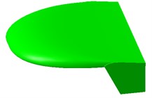
Table 1The data of the flying wing MAV configuration
Parameter | Value |
Chord | 0.15 m |
Span | 0.15 m |
Aspect ratio | 1.0 |
Wing platform | Inverse Zimmerman |
Weight | 0.05 kg |
Cruise speed | 12 m/s |
Max. speed | 14 m/s |
3. CFD simulation method
3.1. Governing equations
For the unsteady compressible flows in a moving and deformable computational domain , the unsteady compressible Reynolds-averaged N-S equations can be written as:
where denotes the vector of conserved variable (mass, momentum and energy), , represents the convective fluxes and represents the viscous fluxes. and are the time varying velocity and normal direction of the interface , respectively. represents the body force per unit volume, corresponds to the momentum source items in this paper.
3.2. Momentum source model
Precise modeling of a propeller is difficult for a variety of reasons. The rotational motion of the blades with respect to the fuselage ensures that the aerodynamic problem is naturally unsteady. What’s more, the low speed of the UAV makes the flow associated with propeller occure at low Reynolds numbers. Designers need to simplify the propellers and predict the aerodynamic performance of the flying wing UAV. The momentum source method may be sufficient as it captures the pressure change.
In the momentum source model the propeller is treated as a black box, where the energy is changed within the fluid by introducing a MSM in the cylindrical region enclosing the propeller. This method has been used in previous rotor modeling studies. The MSM is accomplished by removing the geometry of the propeller, leaving an open passage. In its place a momentum source is applied evenly throughout the propeller region, where the momentum source items are induced by blade element theory. The source terms can be written as:
where and are the airfoil characteristics of the propeller, represents the angle between the propeller blade and the relative velocity vector, is the rate of change of as the blade moves through a revolution, is the absolute velocity of the fluid at the instantaneous blade location (), is the chord of the blade, is the flow density, is the flow viscosity, is the flow Reynolds number, is the flow Mach number and is the number of blades. Note that the term is considered using Beddoes-Leishman (B-L) dynamic stall model in this paper.
3.3. Dual time-stepping algorithm with preconditioning
Low Mach preconditioning is adopted to overcome the system stiffness problem. Meanwhile, preconditioning destroys the time accuracy of the governing equations. A dual time-stepping procedure is employed to solve this problem by introducing a preconditioned pseudotime-derivative into the governing equation as:
where represents the preconditioning matrix, and denote pseudotime and physical time respectively, are primitive variables. The solution at each physical time is treated as steady problems using inner iteration loop in pseudotime.
3.4. Discretization method and iteration scheme
Equation (3) can be discretized in the control volume as:
where , the inviscid flux is calculated using a Roe-type flux difference splitting scheme.
By discretizing the pseudotime term with first order forward difference and discretizing the physical time term with -step backward difference, equation (4) can be written as:
where and is pseudotime and physical time interval respectively.
LU-SGS scheme with matrix-free formulation is used to solve equation (5):
where is the spectral radius of the flux Jacobian matrix.
4. Steady aerodynamics of flying wing MAV
4.1. Mesh generation
Fig. 2Grids around the ducted fan UAV
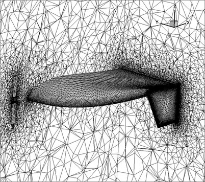
For viscous flow hybrid grids composed of boundary layer viscous structure mesh and unstructured mesh are often preferred because a high-aspect-ratio structured grid with a high degree of clustering near the solid surface is normally more suitable for capturing the boundary layer physics. Fig. 2 illustrates the computational grids around the flying wing MAV. In order to obtain a high-accuracy model and reduce the computational cost, the grids should be scattered in the region where the flow changed slowly and therefore multi-blocked grids technique come into utilization. In this paper hexahedron grids were employed in the momentum source cylinder which can simulate the aerodynamic characteristics of the propeller. Grids are highly clustered on the leading edge, trailing edge and wing tip. In overall the computational domain holds about 900,000 cells.
4.2. Simulation results
The lift and drag coefficients are plotted on Fig. 3 compared with experiment results [13]. As shown in Fig. 3, the computed results agree well with experiment results. The propeller slightly increases lift and drag coefficients by about 5-10 % and increases stall angle by 2° due to retarded flow separation.
Fig. 3Lift and drag coefficients versus angle of attack of flying wing MAV
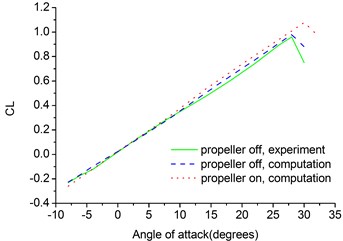
a) Lift coefficient
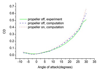
b) Drag coefficient
Fig. 4 illustrates the pressure coefficient and sectional vortex contour of the flying wing MAV. The propeller slightly changes the pressure distribution on the upper face of the flying wing MAV. The wing tip vortex is very strong at 50 % of chord, which contributes to the highly complex flow characteristics of MAV. The wing tip vortex fades as it blows downward by the incoming airstream. The winglet also depresses the wing tip vortex effectively.
Fig. 4Pressure and vortex cloud pictures of the flying wing MAV
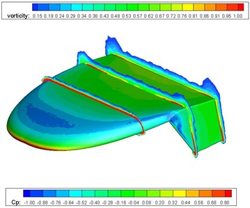
a) Propeller off
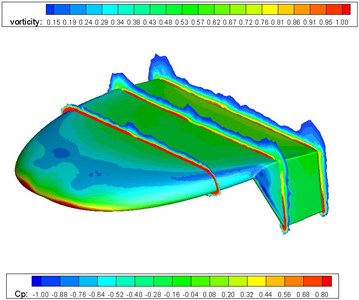
b) Propeller on
5. Unsteady aerodynamics of flying wing MAV
5.1. Unsteady flow over a pitching NACA0012 airfoil
To validate the present method for moving boundary problems, unsteady flow over a pitching NACA0012 airfoil is tested. The pitch motion of the airfoil is expressed by , where denotes the instantaneous angle of attack of the airfoil, is the average angle of attack, is the amplitude and denotes the pitching frequency. For the test case chosen, reduced frequency 0.1, 1.35×10⁵, 0.0385, 10º, 15º.
For the analysis of unsteady flow due to the movement of body, the grid has to change with the body. The most direct grid deformation method is grid regeneration. Grid regeneration at each time step can maintain the grid qualities, but it would be very expensive computationally. Accurate representation of the flow in the near-wall region determines the successful predictions of wall-bounded turbulent flows. Numerous experiments have shown that the value of wall plus () should not be larger than 1.0. Therefore in this paper the wall plus values of the grids used in the calculations are not larger than 1.0. The growth rate of the grid along the normal of wall is 1.12. Fig. 5 illustrates the computational grids around the NACA0012 airfoil. The grid system is generated using two parallel planes of two-dimensional unstructured grids. In overall computational domain holds about 50,000 cells.
Fig. 5Grid around NACA0012 airfoil
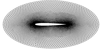
Fig. 6 shows the comparison of the computed results with the experimental values for the lift coefficient and moment coefficient for the pitching NACA0012 airfoil. As shown in Fig. 6, the computational results show reasonable agreement with experimental data [14]. From the results of calculation of the pitching NACA0012 airfoil we can see that the computation method proposed in this paper is valid.
Fig. 6Lift and moment coefficients of pitching NACA0012 airfoil

a) Lift coefficient
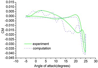
b) Moment coefficient
5.2. Mesh generation
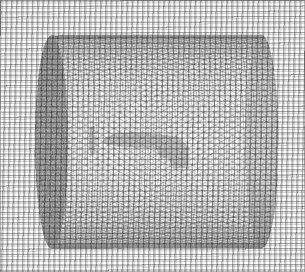
The flying wing MAV can be wrapped up by a body fitted grid, which can be embedded into a Cartesian background grid by applying the overset grid method. The main procedure of overset grid method is the domain connectivity, which consists of three steps: projection, hole cutting and interpolation. The present overset approach is based on the cell centre and all grid cells are divided into three groups: inside cells, fringe cells and outside cells. The inside cells take part in flow computation and the fringe cells carry intergrid communications between different overlapping subgrids. And the outside cells are removed from the initial grids. Fig. 7 illustrates the computational grids of the flying wing MAV. The grid system is generated using hybrid grids including structured and unstructured grids. In overall computational domain holds about 1300,000 cells.
Fig. 7Computational grids of the flying wing MAV
5.3. Simulation results
The pitch motion of the MAV is also expressed by . In the simulation several values are chosen for reduced frequency i. e. 0.15, 0.3, 0.6.1.15×105, 0.0353, 10º, 5º.
The lift, drag and moment coefficients are plotted in Fig. 8. From the results of calculation of the pitching MAV we can see that the hysteresis effect becomes larger at a given angle of attack. The hysteresis curves here are much smoother than the hysteresis curves of the pitching NACA0012 airfoil due to smaller amplitude. The effect of reduced frequency is seen throughout the pitching cycle and is dominant at the maximum and minimum values of the angular velocity during the upstroke and downstroke, respectively. The dynamic derivatives can be calculated by taking the first Fourier coefficients of the time history of lift, drag and moment coefficients.
Fig. 8Lift and drag coefficients of pitching MAV
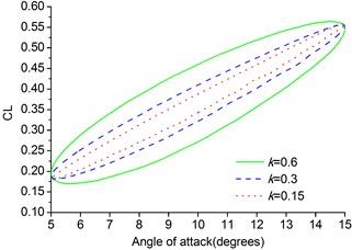
a) Lift coefficient
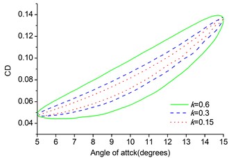
b) Drag coefficient
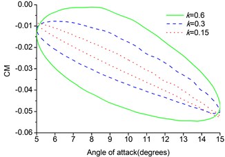
c) Moment coefficient
6. Conclusions
In this paper an effective solution method for aerodynamic characteristics of a flying wing MAV has been developed by using Reynolds averaged N-S equations. The method is based on momentum source method, low Mach number preconditioning and LU-SGS implicit dual time-stepping algorithm on hybrid dynamic meshes. The S-A turbulence model is also applied to capture flow separation. Momentum source items including B-L dynamic stall model are utilized to replace the propeller in the simulation by simplifying the unsteady flow into a steady one. The computational results show reasonable agreement with available experimental data. The method developed in this paper is capable of dealing with steady and unsteady aerodynamic characteristics of flying wing MAV.
References
-
Shyy W., Lian Y. Aerodynamics of Low Reynolds Number Flyers. New York, Cambridge University Press, 2008.
-
Li F., Bai P. Low Reynolds number arodynamics of micro air vehicles. Advances in Mechanics, Vol. 37, Issue 2, 2007, p. 257-268.
-
Ahn J., Lee D. A computational study on the aerodynamic characteristics of a flying-wing MAV design. 30th AIAA Applied Aerodynamics Conference, New Orleans, Louisiana, 2012.
-
Thipyopas C., Moschetta J. Comparison pusher and tractor propulsive for micro air vehicle applications. SAE General Aviation Technology Conference & Exhibition, Wichita, KS, 2006.
-
Guerrero I., Londenberg K. A powered lift aerodynamic analysis for the design of ducted fan UAVs. 2nd AIAA Unmanned Unlimited Systems, Technologies and Operations, 2003.
-
Nygaard A., Dimanlig C. Application of a momentum source model to the RAH-66 Comanche FANTAIL. American Helicopter Society 4th Decennial Specialist’s Conference on Aeromechanics, 2004, p. 21-23.
-
Rajagopalan R. A Procedure for Rotor Performance, Flowfield and Interference. A Persective, 2000.
-
Steijl R., Barakos G. Computational study of helicopter rotor-fuselage aerodynamic interactions. AIAA Journal, Vol. 47, Issue 9, 2009, p. 2143-2157.
-
Cai M., Ang S. Design and analysis of a ducted fan UAV. Journal of Vibroengineering, Vol. 13, Issue 4, 2011, p. 700-711.
-
Gyllhem D., Lawrence D. Numerical simulation of flow around the Colorado micro air vehicle. 35th AIAA Fluid Dynamics Conference and Exhibit, Toronto, Canada, 2005.
-
Boughton S., Attai T., Kozak J. Comparison and validation of micro air vehicle design methods. 42th AIAA Aerospace Sciences Meeting and Exhibit, Reno, Nevada, 2004.
-
Choi S., Ahn J. A computational study on the aerodynamic influence of a pusher propeller on a MAV. 40th Fluid Dynamics Conference and Exhibit, Chicago, Illinos, 2010.
-
Xiao H. A Numerical Method for Unsteady Low Reynolds Number Flows and Application to Micro Air Vehicles. Nanjing University of Aeronautics and Astronautics, 2009.
-
Lee T., Gerontakos P. Investigation of flow over an oscillating airfoil. Journal of Fluid Mechanics, Vol. 512, 2004, p. 313-341.
About this article

