Abstract
A three-dimensional model of the fixed plate of steel ball grinding machines is established using finite element methods. Its distortion and stress status are analyzed, and the natural frequencies and vibration features are obtained. By using the circular area of elastic contacts, the number of effective cutting edges is determined, and a mathematical model is established between the grinding pressure and depth. Then the structural optimization design is programmed with the APDL language of ANSYS. Under its strength being considered, the accurate and reliable design parameters of structures are obtained. Simulation results show that the machining accuracy of steel balls is improved.
1. Introduction
The bearing is an essential part of all types of machinery, and the steel ball is the key part of ball bearings. The manufacturing precision of steel balls has an extremely important impact on the bearing as well as the behavior of the entire mechanical structure. It is shown statistically that steel balls account for 60 % of all factors that affect the noise of the ball bearings and 58.5 % of the bearing failure.
Steel ball grinding machine is one of the key equipment in the grinding ball process. Under certain pressure, grinding disc has the complex relative motion with the ball in order to make it grinded and processed. Grinding disc is installed on the fixed plate. The deformation of the fixing plate directly affects the deformation of the grinding disc, which affects the machining accuracy of steel balls. The deformation and stress of the fixed plate units are important factors to affect the accuracy of steel balls. Ouyang et al. [1] and Mohammed et al. [2] optimized the spindle structural design parameters of steel ball grinding machines from the aspects of static stiffness, dynamic stiffness, vibration and other factors. Although the optimization of the spindle has certain influence on the improvement of the machining accuracy of steel balls, the deformation of the fixed plate directly reduces the machining accuracy of the steel balls. At present, few people analyze the structure of the fixed plate of steel ball grinding machine.
In this paper, in order to improve the machining accuracy of steel balls, the mechanical model of the fixed plate of steel ball grinding machine is established and its structure is optimized by using the APDL language and optimization module of ANSYS [3].
2. Finite element analysis of the fixed plate structure
2.1. Displacement sensitivity analysis
The basic equation for static analysis of finite element method on the fixed plate structure is:
where is the structure overall stiffness matrix, is nodal displacement column vector, is nodal load column vector.
When external loads are unconcerned with design variable , the equation of (1) is differentiated with respect to , which can be represented as follows:
Let:
then:
2.2. Stress sensitivity analysis
When the unit node displacement is known, stress , the first derivative of can be obtained as follows:
where is elastic matrix of element material and only related to the elastic constants of material, is geometric matrix, is the unit node displacement.
2.3. Analysis settings
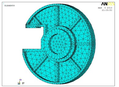
The structural model must be parameterized when the optimization module of ANSYS is used [5]. The fixed plate should be taken into consideration to establish analysis model directly in ANSYS, as shown in Figure 1. Firstly, the properties of material is defined: the material of the fixed plate is HT300, elastic modulus is 1.43×10¹¹ Pa, Poisson's ratio is 0.27, density is 7300 kg/m3, strength limit is 3×10⁸ Pa. Secondly, the element type is defined. The structure of the fixed plate is complex and irregular shapes. Solid 92 in the software library of element type is selected as analyzed element. The structure of the element is a 3-dimensional, 10-node tetrahedral entity with a secondary displacement which is suitable for simulating the irregular meshes. This element is defined by 10 nodes, and each of which has 3 degrees of freedom, with properties as plasticity, swelling, stress stiffening, large deformation and large strain capacity. ANSYS meshing: the model in Figure 1 is divided intelligently into 123429 elements and 189701 nodes as in Figure 2. Finally, the boundary conditions and load cases are imposed. In practical work, the fixed plate is installed on the hydraulic cylinder, the displacement constraint is imposed on the direction which connecting the hydraulic cylinder. When the steel ball grinding machine is working, the fixed plate is steadily pressed by the rotating disc, the displacement constraint is imposed on the direction which is connecting grinding wheel.
Fig. 1The three-dimensional solid model of fixed plate
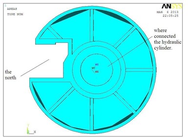
Fig. 2The finite element mesh distribution of fixed plate
2.4. The finite element analysis results of the fixed plate
The overall deformation [6, 7] of the fixed plate is as in Figure 3, where the deformation of the fixed plate is gradually increased from the center outward and it is most obvious at the breach, with a maximum deformation of 2.16×10⁻⁵ m.
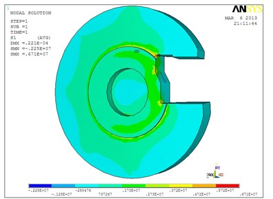
The stress of fixed plate as in Figure 4 shows that the maximum equivalent stress occurs in the places which connects with the hydraulic cylinders and the maximum stress is 6.71×10⁶ Pa, less than the ultimate strength of the material.
Fig. 3The overall deformation of fixed plate
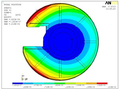
Fig. 4The stress map of fixed plate
3. Modal analysis of the fixed plate
Vibration often causes resonance or fatigue of the mechanical structure which will lead the structural break. The modal analysis is the process which determines the vibration characteristics of the design structure or machinery parts, and obtains the structural natural frequency and mode shape.
3.1. Modal analysis theory and methods of computation
The motion equation of the damping vibration is from [8] as follows:
where is the mass matrix, is the damping matrix, is stiffness matrix, is acceleration vector, is speed vector, is displacement vector, is excitation force vector.
In the case of the damping free vibration analysis of the multi-degree of freedom system, the motion equation is as follows:
Its corresponding characteristic equation is as follows:
where is the free vibration natural frequency, is free vibration mode shapes, which there are natural frequencies and mode shapes in the system with degree of freedom.
3.2. Loading and modal analysis results
Inherent characteristics are constituted by a set of modal parameters such as the natural frequency and vibration mode, which is determined by the structure itself such as distribution of mass and stiffness, and independent of the external load.
The natural frequencies of six modes are obtained by using ANSYS, which are shown in Table 1.
Table 1The natural frequencies of the fixed plate
Modal order | Natural frequency (Hz) | Modal order | Natural frequency (Hz) |
1 | 359.43 | 4 | 509.89 |
2 | 384.23 | 5 | 575.66 |
3 | 467.61 | 6 | 712.83 |
Fig. 5The first order mode
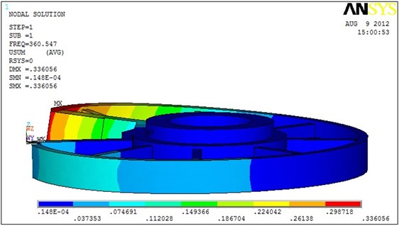
As in Table 1, the natural frequency is much larger than its operating frequency, so the resonance does not occur. As in Figure 5, the bending vibrations are in the axial of the fixed plate, which will reduce the service life of the fixed plate. What’s more, it will affect the stability and balls accuracy in the practical work. Therefore, the stiffness and damping of the structure must be added partially in designing the structure to suppress the effect of the vibration.
4. Structural parameter optimization
4.1. Grinding motion
The steel ball is affected by three surfaces of the grinding disc. The touching surfaces are so small that they can be simplified into three touching points. By taking a steel ball as the research object, which radius is , as in Figure 6, the three points are , and , and revolution angular velocity and rotation angular velocity coexist in the steel ball grinding movement, and the vector of exists in the cross section which contains , and .
Fig. 6Distribution of grinding trace
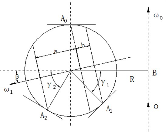
If is grinding pressure of the fixed plate, is the total number of steel balls, is the grinding pressure of a steel ball, which is grinding pressure of too. and are grinding pressure of and . When 0, the dynamic relative relationship is approximated as:
4.2. Grinding pressure
According to the theory of elasticity, the contact deformation areas of the three points are elliptical. The steel ball radius is much smaller than the orbital radius, so the three elliptical regions are approximated as circles. Supposing the three radius of the circle regions are , , . The modulus of the steel ball, the fixed plate and rotated plate are , , and which Poisson's ratios are , , . Then the formulas [8] are as follows:
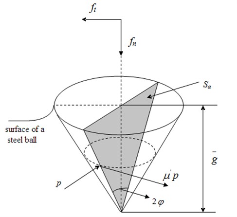
The shape of the abrasive grains are irregular. In order to get it analyzed, abrasive cutting edges are approximated as a conical which point angle is , as in Figure 7. The cross-sectional area of actual cutting is . The surface of the ball is protruded upward because of grinding. The working abrasive cutting edges is contacting with the steel ball with its front half. The pressure of touching surface is , and the friction force of the steel ball is . Then the tangential force and normal force are as follows [10]:
Fig. 7Grinding model of abrasive cutting edge
In its self-rotating circulation, the three points around the surface of the ball do the repeatedly grinding under the same circular trace. is the number of rotation laps. Supposing there is no slip grinding balls for motion and analyzing the grinding of , it can be seen that if the grinding depth of the steel ball is the grinding amount of a grinding cycle is , the number of effective cutting is , where is the number of effective cutting in per unit area. If the length of the undeformed chip in the circle region is , the section area of the undeformed chip is . Supposing the section modulus of the undeformed chip is , the average abrasive cutting depth is which satisfies the following relation as:
While the steel ball is grinded at , the number of cutting is . According to the formulas (16-18), the tangential force and normal force are obtained as follows:
Excluding the collision among the balls, let , it can be obtained from the above equations as follows:
According to formula (21), if the steel ball, grinding discs and abrasive are ascertain, grinding pressure is determined by grinding depth, steel ball radius and orbital radius. Then the grinding surface pressure of the fixed plate can be determined, which provides theoretical support for the following parameter optimization design.
4.3. Structural optimization model
Because the notch of the fixed plate of steel ball grinding machine is the material inlet, the center of the ring circle which connected to the hydraulic cylinder is away 0.3 m from the center of the fixed plate circle, against the notch. Which leads to the situation that the deformation of the fixed plate around the notch is the maximum and uneven which causes the unevenness and lower accuracy of the grinding steel balls. In the paper the structure of the fixed plate is improved to reduce the width of the notch in the case of the small impact of the amount of material, then by making the ring connected to hydraulic cylinder move to the notch as far as possible. The optimal offset can be found by the optimization design module of ANSYS [11]. The maximum amount of deformation must be minimized so that the deformation of the fixed plate can be more even. Meanwhile, reducing the notch appropriately will increase the local stiffness of the structure and reduce the vibration of the fixed plate.
Because the design variables can not be minus in ANSYS, when modeling the fixed plate, the abscissa of the center of the fixed plate is 0.4 m, the abscissa of the center of the ring circle is 0.4 m, the abscissa of polarized distance is . Grinding surface is imposed pressure . Because is a fixed value, is the design variables, and the maximum stress is state variables, which should be less than the ultimate strength of the material. The maximum amount of deformation of the fixed plate is the objective function. Then the structure optimization model is as follows [12]:
Objective function: ; ,
Design variables: 0.390.41,
State variables: ,
where is the maximum amount of deformation, is the abscissa of the center of the ring circle, the polarized distance is . The lapping surface is imposed pressure . If is minus, the ring is at left side. Strength of the material is 3×10⁸ Pa. The unit of the design variables and objective function is m, and the unit of state variables is Pa.
4.4. Analysis of optimization results
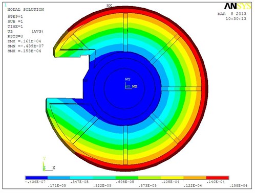
In the initial design, is 0.43 m, objective function is 2.16×10⁻⁵ m. As in Figure 8 and 9, after 15 iterations in the optimization process of ANSYS, the optimized design variables is 0.396 m and the objective function is 1.575×10⁻⁵ m. Compared with the original program the objective function is decreased by 27 %. As in Figure 10, the structural deformation of the fixed plate is more even.
Fig. 8Optimization process data
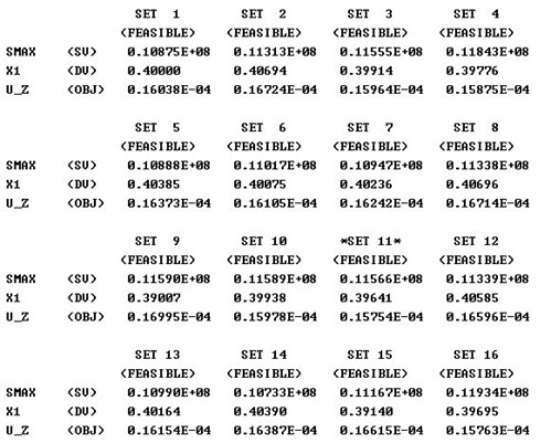
Fig. 9Optimization objective function graph
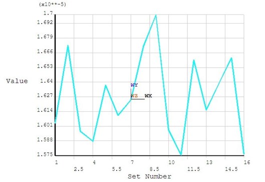
Fig. 10Optimized structural deformation
5. Conclusions
The axial stress and strain of the fixed plate of steel ball grinding machine have a great impact on the precision of steel balls. The three-dimensional finite element model of the fixed plate is established by ANSYS software, and its axial stress and strain are analyzed and calculated. If the external loads and the natural frequency of the structure are similar, resonance occurs which causes structural yield. The natural frequency and vibration graph of the fixed plate are obtained by modal analysis. Therefore, the load frequency and the natural frequency should be avoided to be the similar in the structural design.
Using the APDL language of ANSYS, the structural optimization design program is conducted, which optimization results is reduced by 27 % relatively to the original design and the deformation is more even so that the accuracy of steel balls is improved, which provides a feasible solution for the development of the new generation of steel ball grinding machines.
References
-
Jinghui Ouyang, Wang Li Structure optimization design of the spindle of steel ball lapping machine. China High Technology Enterprises, Vol. 19, 2011, p. 19-20.
-
Mohammed A. Alfares, Abdallah A. Elsharkawy Effects of axial preloading of angular contact ball bearings on the dynamics of a lapping machine spindle system. Journal of Materials Processing Technology, Vol. 136, 2003, p. 48-59.
-
Fengxian Xue, Renxi Hu, Shiyan Kang ANSYS12.0 Mechanical and structural finite element analysis from the entry to the master. Chain Machine Press, Beijing, 2011.
-
Dongchen Qin, Ying Liang, Liping Chen Research on structural optimization design for key parts of a six-face presser. China Mechanical Engineering, Vol. 18, Issue 6, 2007, p. 697-701.
-
Yaodong Gao, Xuejie Liu ANSYS 50 cases of mechanical engineering applications essence. Publishing House of Electronics Industry, Beijing, 2011.
-
Deping Liu, Hang Zhang, Tao Zheng, Yufeng Su Finite element analysis of high-speed motorized spindle based on ANSYS. The Open Mechanical Engineering Journal, Vol. 5, 2011, p. 1-10.
-
Ernesto Grande, Maura Imbimbo, Elio Sacco Finite element analysis of masonry panels strengthened with FRPs. Composites Part B, Engineering, Vol. 45, Issue 1, 2013, p. 1296-1309.
-
B. I. Zubrenkov, V. V. Sen'kina Modal analysis of the structure of rotary machines with roller bearings. Russian Engineering Research, Vol. 30, Issue 5, 2010, p. 442-445.
-
Shizhu Wen Principles of Tribology. Tsinghua University Press, Being, 1990.
-
Zhuangsi Kexiong Grinding Technology. China Machine Press, Being, 2007.
-
John Swanson Ansys Incorporation Release 10.0 Documentation for Ansys: Subproblem Approximation Method and First Order Optimization Method [EB/DK], 2005.
-
Lee Hyun-Ku, Kim Moo-Suk, Kang Koo-Tae An experimental research for the optimization of the gear lapping machine's operating condition. Transactions of the Korean Society for Noise and Vibration Engineering, Vol. 7, Issue 20, 2010, p. 665-679.
About this article

This work is supported by the Science and Technology Research and Development Project of Hebei Province under Grant No. 12212110D.
