Abstract
A series of centrifuge shaking table tests were conducted at the National University of Singapore to examine the seismic softening behavior of pile-raft foundation constructed in clayey soil site subjected to far field earthquake. The model test results show that strain softening and stiffness degradation feature strongly in the behavior of the clay, which was manifested as an increase in resonance periods of the surface response with level of shaking and with successive earthquakes. The softening degree is greater in near field clay around pile-raft foundation than in clay far away from foundation. While this was not the case for the pile-raft foundation, because resonance periods of piled raft and bending moment envelopes of piles almost keep unchanged during repeated earthquake excitations, in some sense this indicates softening extent of foundation was not significant as soft clay. Moreover, seismic behavior of pile-raft was hardly affected by the stiffness degradation of surrounding clay, its seismic behavior in a great degree decided by properties such as mass and flexural rigidity. Finally, the indications from centrifuge tests were back-analyzed by conducting ABAQUS simulation, including 2 types of constitutive soil models with and without considering seismic softening. The acquired results could be served as a reference for seismic design of pile foundation constructed in soft clay site when subjected to far field earthquake with relatively long period and duration.
1. Introduction
In the areas underlying soft clay, pile foundations are extensively used to achieve the bearing capacity required to support heavy superstructure loadings, such as those imposed by tall buildings. The behavior of pile or pile-raft foundations under earthquake loading is an important factor affecting the performance of many essential inland or offshore structures such as bridge, harbors, tall chimney, wharf, etc. The performance of pile foundations during past earthquakes has shown that piles in firm soils generally perform well, while in soft or liquefied ground may be problematic at times [1]. Pile distress and failure during seismic shaking, although difficult to observe in post-earthquake site investigations, have been well documented [2].
It is well known that the mechanical behavior of soil under dynamic loading, such as sea waves, earthquakes and traffic loading, differ significantly from those under quasi-static loading. The nonlinear stress-strain response associated with soft clays under cyclic loading was experimentally verified [3-4]. Brennan et al. (2005) examined shear modulus and damping in dynamic centrifuge tests, and showed that soft clay exhibited strain softening, as reflected in reduced values with increasing strain levels [5]. The presence of piles or pile-raft foundations in soft clays introduces additional complexity to the problem. A typical case is the 1985 Mexico city earthquake disaster, although the epicenter is over 400 km far away from the city, the result was very serious, mainly because most of piled buildings in the city were constructed onto thick soft clay bed, when earthquake wave transmitted from rock bed to ground surface, it was strongly amplified and filtrated to a motion with relatively long period and duration, at the point which was very near the first-mode period of most buildings (0.1 N), the resulted resonance effect made a serious destroy for buildings around 10 stories. The geology condition of Singapore city is very similar to Mexico city, who also constructed onto soft deep marine clay, and with great concern on encountering a far field earthquake triggered by Sumatran fault. This study will conduct some related studies. The acquired results would be served as a reference for cities with similar conditions, such as Shanghai, Bombay, Bangkok, etc.
Wilson (1998) and Christina et al.(1999) studied the performance of pile foundations in sandy soil using the large servo-hydraulic shaking table on the 9-m-radius centrifuge at UC Davis, and proposed design charts for engineers [1, 6]. Nikolaou (2001) presented analytical results for piles in homogeneous and layered soil, and deduced a dimensionless formula to estimate the maximum bending moment generated in pile during seismic shakings [7]. However, all these analyses were based on numerical methods with assumption that the soil was elastic, which cannot reflect its real properties. Snyder (2004) showed that the clay stiffness degraded around the single pile during cyclic lateral load tests in the field [8]. However, the study did not include the seismic behavior of pile-raft under different superstructural loadings. Finn (2005), using numerical analysis as well, showed that the clay around a pile undergo stiffness degradation during seismic shaking, but still did not consider the seismic behavior of foundation [9]. Banerjee (2007) studied seismic response of pile foundations using centrifuge and numerical modeling. However, in his study, only the acceleration of the piled raft was discussed, the bending moment of pile and softening effect for both near and far field clay were not included [10].
In this paper, the results from a series of centrifuge shaking table tests conducted at the National University of Singapore (NUS) are presented. The centrifuge experiments were performed to examine seismic behavior of pile-raft foundation in soft clay condition, with special focus on the softening behavior of pile-raft structure and clay (including near- and far-field clay) due to successive earthquake shaking. Centrifuge test contains acceleration measurement by accelerometers placed in raft and different position of clay bed and bending moments of the pile from strain gauges instrumented along the model piles. Besides centrifuge tests, ABAQUS simulation was also conducted to back-analyse all the test results, the used soil constitutive models included a developed model (Umat) with considering seismic softening effect, and another embedded in ABAQUS material group which doesn’t consider softening. All the results in this study were discussed in prototype unless otherwise stated.
2. Experimental setup and configuration of the centrifuge models
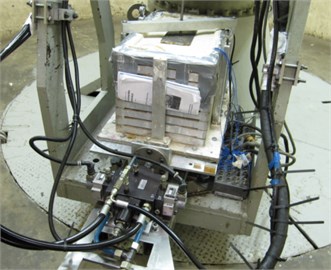
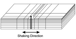
All the experiments were conducted at 50 g on the NUS Geotechnical Centrifuge, which has a radius of 2 m and compromises a balanced arm with dual swing platforms. The centrifuge has a capacity of 40 g-ton and a maximum acceleration of 200 g, shown in Fig. 1. Earthquake waves can be input to model through a closed-loop electro-hydraulic servo-control shaking table that was fixed on the swing platform of centrifuge. The laminar box with inner dimension of 530 mm length by 300 mm width by 350 mm height was mounted onto the shaking platform, which is constructed from aluminum alloy and comprises nine rectangular laminar rings. More details on the experiment set-up are available in Ma Kang et al. (2012) and Banerjee et al. (2007) regarding the test set-up for this study shown in Fig. 2 [10, 11].
The clay bed used in the centrifuge model tests was prepared using kaolin powder mixed with water in a ratio of 1:1.2, and operated in a deairing chamber for about 5 hours. After mixing, the slurry was transferred into the rubber-lined laminar box in several pours, so that the transducers could be placed at the desired locations and depths.
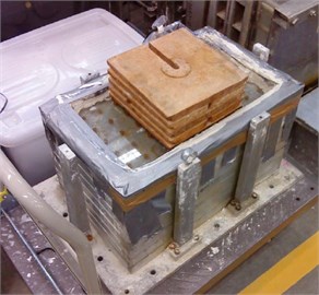
The completed slurry mixture was then subjected to both 1 g and 50 g consolidation processes to develop the representative strength profile and stress history. The 1 g consolidation was firstly carried out to pre-compress the clay beds, so as to reduce the time required for the subsequent in-flight consolidation. Dead weights were applied in stages, up to a total load of about 100 kg, which corresponds to an effective overburden stress of about 5 kPa at the top of the clay bed. To ensure a uniform pressure distribution acting on the clay bed, the weights were applied on a thick perspex plate resting on a geotextile layer placed over the surface of the clay slurry. The 1 g loading condition was maintained for 7 days (Fig. 3). After that, the dead weights and the plate were removed, following which the laminar box was mounted on the centrifuge together with the shaker and other accessories. It was then subjected to in-flight centrifuge consolidation under 50 g until the degree of consolidation along the entire depth was 70 % or more. According to Terzaghi’s 1-D consolidation theory, the consolidation time was expected to take about 10 hrs. The geotechnical properties of the kaolin clay used in this study are given in Table 1.
Fig. 1NUS geotecnical centrifuge
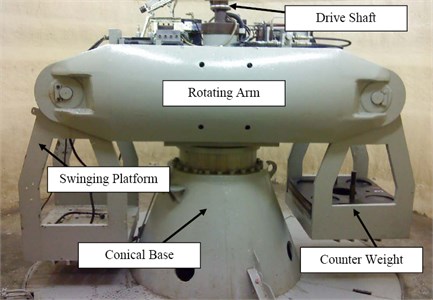
Fig. 2Laminar box-shaker assembly on centrifuge arm
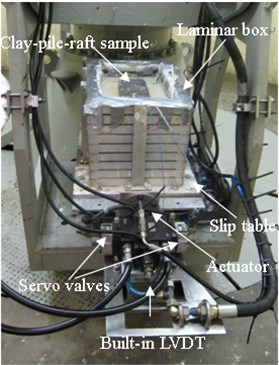
Fig. 31 g and 50 g consolidation of kaolin clay
a)
b)
Table 1Geotechnical properties of kaolin clay
Properties | Kaolin Clay |
Bulk unit weight (kN/m3) | 16 |
Water content | 66 % |
Liquid limit | 80 % |
Plastic limit | 40 % |
Coefficient of permeability (m/s) | 1.36∙10-8 |
Initial void ratio | 1.74 |
Angle of friction | 25° |
The raft (10.5 m×5.6 m×0.5 m) was supported on 4 widely-spaced piles (0.5 m diameter and 13 m long). In the centrifuge tests, model pile-raft systems were replicated by 1.0 cm in diameter and 26 cm long bar, connected to a rigid steel plate (21 cm×10.1 cm×1 cm). The raft was partially embedded in the ground so that there also exist direct interaction between raft and soil. This is a commonly used foundation system for soft clays in Singapore. A pile-raft arrangement is used instead of a single pile because the objective is to study fixed-head piles. With a single pile, it would have been very difficult to realize the required rotational constraint on the pile head. The minimum clear spacing between the pile and the internal wall of the box is larger than 10 times the pile diameter. These spacing were chosen to keep the pile-to-pile and pile-wall interaction to a minimum within the available space. Superstructure loading on the raft was simulated using steel plates, which were added in stages onto the top of raft to simulate the effects of above-ground inertial forces. There were total 3 steel plates of about 2 kg each was placed in three stages to simulate the loading cases on the model (Table 2). The load on the raft was so chosen to give a FOS of about 2.5 against structural failure at highest loading level. The tested pile-raft foundation need to install in the proper position in clay bed in advance and fixed by a rigid frame before in-flight centrifuge consolidation, as shown in Fig. 3.
Table 2Different loading case of the added weight
Loading cases | Superstructure load | Model mass (kg) | Prototype mass (ton) |
Load 1 | Raft only | 2.95 | 368 |
Load 2 | Raft + 1 plate | 4.84 | 605 |
Load 3 | Raft + 2 plates | 6.90 | 863 |
Each equivalent prototype load case was tested on 3 types of piles, these were a) solid stainless steel pile of diameter 0.5 m, b) hollow stainless steel pile of outer diameter 0.5 m and thickness 50 mm, and c) stainless steel pile of outer diameter 0.5 m and thickness 50 mm with concrete in-fill. In order to make convenient for the study, the density and moduli of concrete and hollow piles, were reduced and normalized by solid pile, as shown in Table 3.
Table 3Properties of 3 types piles used for the study
Pile type | Length (m) | Diameter (m) | (m4) | Flexural rigidity () / KN-m2) | Equivalent modulus ( / GPa) | Equivalent density (, Kg/m3) |
Solid | 13 | 0.5 | 644271 | 210 | 7800 | |
Concrete | 424360 | 138 | 4362 | |||
Hollow | 380377 | 124 | 2826 |
The test configuration is shown in Fig. 4, the transducers were placed at the prescribed positions. Accelerometers A2 and A4 were placed on the clay surface at prototype distances of about 1.5 m and 6.5 m respectively away from raft. Thus accelerometer A2 captures ground surface acceleration near to the pile-raft whereas A4 captures ground surface acceleration farther away. These are loosely termed “near-field” and “far-field” accelerometers, respectively. Moreover, along pile length, five strain gauges labelled S1~S5 were installed to capture bending moment of pile during earthquake shaking.
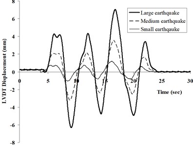
The input motions used in the centrifuge experiments were generated using response spectra from earthquakes measured in Singapore from Sumatran events. These typically have long periods and durations. Owing to the limited duration of excitation which the shaking table can generate, low frequency waves with prototype periods exceeding 25 s were removed from the earthquake spectra before generating the time histories. Three different input motions were thus generated, corresponding to a large, medium and small earthquake event. Figure 5 shows the three scaled input motions, in model unit, fed into the displacement-controlled servo-actuators. In each centrifuge experiment, the model was subjected to 6 earthquake events. These earthquakes were “fired” in 2 cycles, each comprising a small, medium and large earthquake (PGA equals to 0.022 g, 0.052 g, and 0.13 g, respectively) that was triggered sequentially.
Fig. 4Centrifuge model views and instrumentation layout in tests
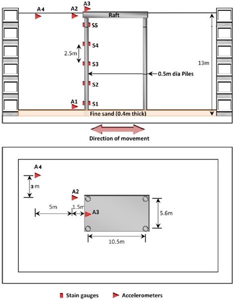
Fig. 5Displacements used as the centrifuge input motion
3. Softening of clay bed
3.1. Acceleration response
Fig. 6 shows typical acceleration time histories from medium earthquake within the first cycle for the solid pile, while Fig. 7 gives the corresponding response and amplification spectra. In this study, the amplification spectra were obtained by dividing the response magnitude of expected location (such as clay surface and raft, herein) by the corresponding magnitude at the same frequency at the base. As Fig. 7 shows, maximum clay surface amplification occurs at the near-field for a period of about 2.3 sec whereas the raft shows maximum amplification at a much shorter period. Furthermore, the maximum amplification at the far-field accelerometer is significantly lower than that at the near-field, suggesting that there is differential acceleration between the pile-raft as well as the near- and far-field regions. This indicates that clay motion (both near- and far-field) cannot be representative of raft motion, using seismic motion of clay surface (always adopting free-field motion without considering interaction between soil and foundation) directly as base input motion in traditional seismic resistance design for structure is not strict.
Fig. 6Typical acceleration time histories measured from centrifuge test
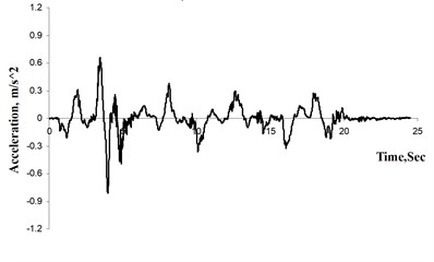
a) Base, A1
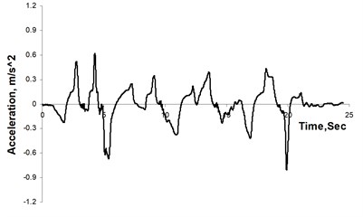
b) Clay surface (near field), A2
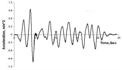
c) Top of raft, A3
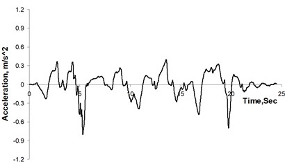
d) Clay surface (far field), A4
Fig. 7a) Response spectra, b) Amplification at clay surface (A2 and A4), and raft (A3)
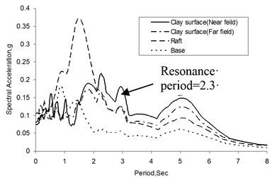
a)
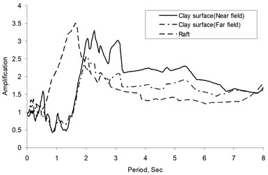
b)
As discussed above, Fig. 8(a), (b) summarized all the periods for near- and far-field clay, respectively, under different load cases and PGAs. Generally speaking, for all 3 types of piles, both accelerometers at the near- and far-field clay surface shows an increase in period of maximum amplification, herein termed resonance period, with peak ground acceleration (PGA). Furthermore, all parameters being the same, the resonance period was also higher in the second cycle. Since the inertia of the soil and the pile-raft remains unchanged, this would suggest that there is some softening of the soil with increase in ground acceleration and with successive earthquake. This is not unreasonable; the first can be explained in terms of the strain softening behavior of clay (e. g. Idriss, 1978, Vucetic and Dobry, 1991, Teachavorasinskun et al. 2001, etc.) and the second can be attributed to the remoulding of the soil by the preceding earthquakes, which is also likely to cause softening. Moreover, as compared between Fig. 8(a), (b), for 3 types of piles under the same conditions, the increase in the resonance period is generally much more pronounced for the near-field acceleration than the far-field acceleration. This would be consistent with the notion of remoulding since one would surmise that the near-field soil would be more likely to undergo a higher degree of remoulding than the far-field soil, as Finn 2005, shown in Fig. 9. The study herein gave another skillful explanation from totally different angle of period indication.
Fig. 8Resonance periods of far-field clay surface
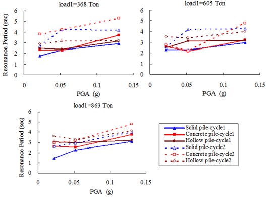
a) (A2)
b) (A4)
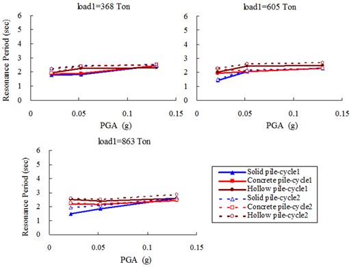
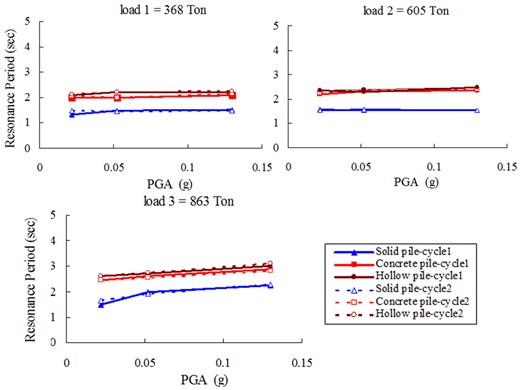
As shown in Fig. 10, in contrast to the clay, the resonance period of raft supported by 3 types of pile does not change significantly over the two cycles of earthquakes. For the small and medium masses, the resonance period is largely independent of PGA. For the largest mass, the resonance period appears to lightly increase with PGA, especially more obvious for solid pile. For the same mass and PGA, the resonance period of the raft is always lower than that of the soil layer as shown in Figure 7(b). This appears to suggest that, at least for the small and medium masses, the pile-raft response is essentially elastic. For the largest mass, there may be some non-linearity and softening. However, for all masses, there appears to be little or no softening arising from previous earthquakes, which was observed for the soil layer. This point is fundamentally different from soil behavior. Moreover, raft periods of hollow pile, generally show a highest value in all types of pile, mainly because of its lowest flexural rigidity in three.
Fig. 9Finite element models
a) Finite element model
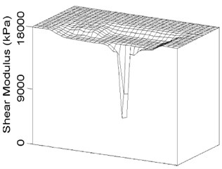
b) Shear moduli around pile (by Finn 2005)
Fig. 10Resonance periods of raft (A3)
3.2. Pile bending moment
Fig. 11 shows a typical set of time histories of bending moment recorded by different strain gauges installed along the solid pile under the condition of large earthquake (0.13 g) and largest mass (863 ton). It is observed that, for all 5 levels, the maximum bending moments generally occur around 5.1 sec, then respective maximum bending moments are chosen to plot against the pile depth, i.e. bending moment envelopes with 2 cycles as shown in Fig. 12.
As shown in Fig. 12, still taking solid pile for instance, under different PGAs, the maximum bending moments of the pile are developed near the pile head (S5), which is consistent with the fact that the pile head is quite rigidly connected to the bottom of the raft. It is also observed that the maximum bending moment near the pile head increases with the earthquake magnitude. Furthermore, Figure 12 also shows that the positive bending moments develop near the top of the pile, which progressively reduces to negative moments near the bottom of the pile. However, the negative bending moments are relatively insignificant compared to the positive moments. This is similar to the bending moment distribution curves for laterally loaded piles, and suggests that, the surrounding clay may able to provide lateral support for the piles. This observation is similar to that reported Nikolaou et al. (2001) and Wang et al. (2010), who noted that an active pile length exists for the head-loaded piles, especially for relatively flexible piles [7, 12]. Below this depth, the pile would experience bending moments no more than 5 % of maximum positive bending moment developed near the top of the pile.
Fig. 11Measured time histories of bending moment from centrifuge test
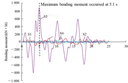
Fig. 12Bending moment envelopes of solid pile within 2 cycles of earthquakes
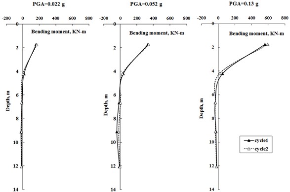
As be seen from Fig. 12, the bending moments didn’t change significantly between the first and second cycle of earthquake loadings, including maximum bending moment and envelope shape. This indicates that, for a given earthquake excitation, the maximum bending moment in a fixed-head pile is predominantly governed by the flexural rigidity and mass imposed onto pile-raft system. Together with response spectra discussed above, this seems to indicate that the softening extent of pile-raft foundation is very low, i.e. it would not become “soft” as soil during repeated earthquake excitions, and in turn lose bending resistance or bearing capacity for supporting superstructure loading. Moreover, seismic degradation of clay doesn’t apply significant influences on moment response. For other 2 types of piles, i.e. concrete and hollow piles, the measured results also show very similar indications as shown by the solid pile.
4. ABAQUS simulation
In order to check the measured results as well as indications from centrifuge tests, using ABAQUS 6.12 to build up corresponding numerical models to back-analyse [13]. The main idea is to adopt 2 types of soil constitutive models, one is the developed model (Umat) called HyperMas by Banerjee (2010) with considering the seismic softening effect of clayey soil, and the another is the hypoelstic model available in ABAQUS material group without considerting softening [14].
Since seismic softening behavior for soft clay has been commonly and definitely documented, so herein the most concern is focused on the softening of pile-raft foundation, i.e., to know if any differences on response spectra of piled raft and bending moment of pile when using the 2 totally different soil constitutive models?
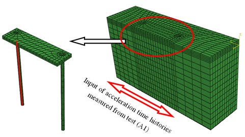
Considering the symmetry of the problem, a half 3-D model of pile-raft-clay system was built up as shown on Fig. 13, wherein the model was discretized into a total of 7742 20-noded solid brick elements and 64 (32×2) 3-noded beam elements to get the bending moment. For other 2 types of piles, concrete and hollow, the model were the same, only the density and moduli using equivalence value as shown in Table 3.
Fig. 133-D ABAQUS model
4.1. Clay constitutive model
4.1.1. Hypoelastic model
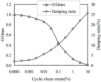
The clay was firstly behaved as a hypoelastic model embedded in ABAQUS material group. This model assumed that the modulus of elasticity and Poisson’s ratio are functions of the strain invariants. Although it doesn’t reflect the hysteretic and degradation behavior, the non-linearity of clay is considered. In this study, strain dependent stiffness was adopted from Vecetic and Dobry’s (1988) shear modulus () versus shear strain curve (Fig. 14).
Fig. 14Shear modulus reduction and damping ratios with shear strain level
For NC (1) speswhite kaolin clay, Viggiani et al. (1995) presented a useful equation to calculate maximum shear modulus as [15]:
where:
In the equations, is effective unit weight and about 6 kN/m3 for soft kaolin clay. Asusuming , using Jaky’s relationship:
The clay bed in ABAQUS model in this study comprises 14 layers, so at the mid-depth of each layer can be calculated as shown in Table 4.
Table 4Parameters of clay bed (from clay surface to bottom)
Layer No. | Layer thickness (m) | (KPa) | Depth of mid-layer (m) |
1 | 0.5 | 2081 | 0.25 |
2 | 0.5 | 4265 | 0.75 |
3 | 1.0 | 6839 | 1.50 |
4 | 1.0 | 9707 | 2.50 |
5 | 1.0 | 12168 | 3.50 |
6 | 1.0 | 14406 | 4.50 |
7 | 1.0 | 16453 | 5.50 |
8 | 1.0 | 18382 | 6.50 |
9 | 1.0 | 20209 | 7.50 |
10 | 1.0 | 21952 | 8.50 |
11 | 1.0 | 23625 | 9.50 |
12 | 1.0 | 25237 | 10.50 |
13 | 1.0 | 26786 | 11.50 |
14 | 1.0 | 28298 | 12.50 |
4.1.2. HyperMas model (Umat)
This soil model has been developed and more details can be referred in Banerjee (2010) [14]. This model encompasses the concepts of small strain non-linearity [16], hysteretic stress-strain behaviour [17] and cyclic degradation of backbone curve [18] for the application to dynamic problems such as current earthquake response. The non-linear elasticity was modelled by varying the shear and bulk moduli as a function of the mean effective stress, the overconsolidation ratio and the corresponding strain increment since the last strain reversal [15]. The hysteretic stress-strain behaviour for unloading and reloading is modelled using the Masing rule [19]. The progressive degradation of the backbone curve under repeated loading was modeled using Idriss’s concept of degradation index [18].
4.2. Boundary condition
To simulate laminar box movement, linear multi-point constrains were applied to the two vertical faces normal to the earthquake motion to make the nodes at opposite ends of the domain and at the same depth move in unson with each other. In addition, vertical displacement restraints were applied at all 4 vertical faces while the bottom of the model was constrained against vertical movement. The symmetry face was additionally applied symmetry displacement boundary.
4.3. Earthquake excitation
The input earthquake was prescribed at the base of the model in the form of an acceleration time history, which was taken from the centrifuge accelerations at the base of clay bed (accelerometer A1), from the small, medium, and large earthquakes.
4.4. ABAQUS results analysis
4.4.1. Acceleration time histories and resonance periods
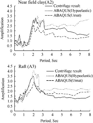
Corresponding to Fig. 6, Fig. 15 gives the computed acceleration time histories of near-field clay (A2) and raft (A3) by using 2 different soil models, together with measured results from centrifuge tests. As can be seen in Fig. 15, for 2 soil models, Despite some discrepancies, the computed response could both provides a generally good fit to the measured accelerations at different locations. The agreement seems to be a little more reasonable in case with Umat model.
Fig. 15Comparison of acceleration time histories between ABAQUS simulation and centrifuge test
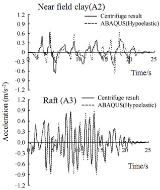
a) Soil model using Hypoelastic
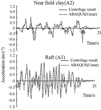
b) Soil model using HyperMas (Umat)
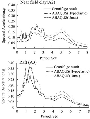
Figure 16 shows the computed vs measured response spectra for the time histories of Figure 15. Again, generally, for both soil models, the agreement between ABAQUS and the measured responses appears to be reasonable. In particular, the resonance periods of maximum amplification in both the clay and the structure are reasonablely replicated.
Fig. 16Comparisons between ABAQUS simulation and centrifuge test
a) Comparison of response spectra
b) Comparison of amplification
Figure 17 summarizes the computed resonance periods at the solid piled raft under different inertial loadings and PGAs. In spite of totally different consideration of softening effect in 2 soil models, the results of two are very close and both reflect the experimental trend reasonably well. This appears to indicate that, the softening effect of soil has little influence on the foundation seismic behavior as tests revealed above. The pile-raft response in a great degree was decided by its own properties other than surrounding soils. The computed results for other 2 types of piles also give similar conclusions as solid one.
Fig. 17Comparison of raft periods between ABAQUS simulation and centrifuge test
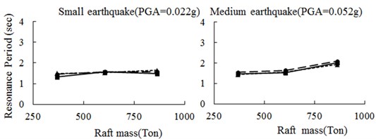
a)
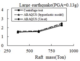
b)
4.4.2. Bending moment
Similar to Fig. 11, time histories of bending moment at those five levels where strain gauges are mounted on the pile can be also computed by ABAQUS using 2 types of soil models. With the same operation, as shown in Fig. 18, peak moments at all 65 integration points of 32 beam elements picked out from computed time histories of moments, are plotted against the pile depth along with the centrifuge results at five levels.
Fig. 18Envelopes of pile bending moment by ABAQUS simulation and centrifuge test
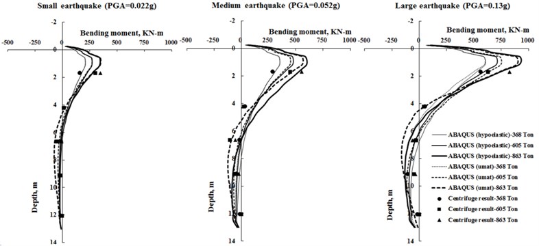
As can be seen in the figure, the experimental values fall very close to the computed profile, and 2 numerical models results were generally very close, and both predicted experimental trends and maxmum moments value reasonably well. Although non-linear hypoelastic soil model has some limitation in modeling softening behaviour of clay, but it can generally agree with the bending moment envelopes as Umat model quite well. Hence, again, this indicates that the seismic behavior of pile-raft was hardly affect by the softening of surrounding clay as stated above. The same indication can also be seen in all 3 types of tested pile.
5. Conclusions
By conducting a series of centrifuge shaking table tests and ABAQUS simulations on 3 types of piles under different cases (different superstructure masses and PGAs) constructed in soft clay, and based on the acquired resonance periods of clay and raft as well as bending momet of piles, some interesting indications can be drawn as following:
(1) Soft clay for both far-field (or free field) and near-field around existing pile-raft foundation shows a softening seismic behavior which was manifested as an increase in resonance periods of the surface response with level of shaking and with successive earthquakes. And moreover, remoulding effect arising from kinetic interaction between pile-raft foundation and clay may deepen softening of near field clay in some degree.
(2) For pile-raft foundation, since measured resonance periods of piled raft and bending moment envelopes of pile were almost unchanged during successive seismic shakings, this indicated softening of pile-raft foundation installed in soft clay was not as significant as clay, its dynamic behavior in a great degree was decided by its own properties such as system mass, flexural rigidity, and PGAs, etc.
This paper studied softening effect of pile-raft foundation constructed in clayey soil condition. The acquired conclusions were mainly applicable to far-field earthquakes with relatively long duration and low PGA, and more studies are needed on other relatively strong earthquakes in the further studies.
References
-
Wilson D. Dynamic centrifuge tests of pile supported structures in liquefiable sand. Ph. D. thesis, University of California, Davis, 1998.
-
Mizuno H. Pile damage during earthquake in Japan. Dynamic response of pile foundation, New York, American Society of Civil Engineers, 1987, p. 53-78.
-
Xia Y., Nassif H., Hwang E. S., Linzell D. Optimization of design details in orthotropic steel decks subjected to static and fatigue loads. Transportation Research Record, Journal of the Transportation Research Board, Vol. 2331, 2013, p. 14-23.
-
Puzrin A. M., Burland J. B. Non-linear model of small-strain behaviour of soils. Geotechnique, Vol. 48, Issue 2, 1998, p. 217-233.
-
Brennan A. J., Thusyanthan N. I., Madabhushi S. P. G. Evaluation of shear modulus and damping in dynamic centrifuge tests. Journal of Geotechnical and Geoenvironmental Engineering, ASCE, Vol. 131, Issue 12, 2005, p. 1488-1497.
-
Christina J. Curras, Boulanger Ross W., Kutter Bruce L., Wilson D. Seismic soil-pile-structure interaction experiments and analyses. Journal of Geotechnical Engineering, ASCE, Vol. 125, Issue 9, 1999, p. 345-369.
-
Nikolaou S., Mylonakis, G., Gazetas G., Tazoh T. Kinematic pile bending during earthquakes: analysis and field measurements. Geotechnique, Vol. 51, Issue 5, 2001, p. 425-440.
-
Snyder J. L. Full scale test lateral load tests of a 3x5 pile group in soft clays and silts. MSc thesis, Brigham Young University, USA, 2004.
-
Finn W. D. A study of piles during earthquakes: issues of design and analysis. Bulletin of Earthquake Engineering, Vol. 3, 2005, p. 141-234.
-
Banerjee S., Goh S. H., Lee F. H. Response of soft clay strata and clay-pile-raft systems to seismic shaking. Journal of Earthquake and Tsunami, Vol. 1, Issue 3, 2007, p. 233-255.
-
Ma K., Banerjee S., Lee F. H., Xie H. P. Dynamic soil-pile-raft interaction in normally consolidated soft clay during earthquakes. Journal of Earthquake and Tsunami, Vol. 6, Issue 3, 2012, p. 1250031.
-
Wang Y. J., Wei, Q. C., Shi J., Long X. Y. Resonance characteristics of two-span continuous beam under moving high speed trains. Latin American Journal of Solids and Structures, Vol. 7, Issue 2, 2010, p. 185-199.
-
ABAQUS Standard User’s Manual Version 6.12. Hibbit, Karlsson and Sorensen Inc., Pawtucket, RI, 2012.
-
Banerjee S. Centrifuge and numerical modelling of soft clay-pile-raft foundations to seismic shaking. National University of Singapore, 2010.
-
Viggiani G., Atkinson J. H. Stiffness of fine-grained soils at very small strains. Geotechnique, Vol. 45, Issue 2, 1995, p. 249-265.
-
Dasari G. R. Modeling of the variation of soil stiffness during sequential construction. Ph. D. Thesis, Cambridge University, United Kingdom, 1996.
-
Liu H., Ling H. I. Modeling cyclic behavior of geosynthetics using mathematical functions combined with masing rule and bounding surface plasticity. Geosynthetics International, Vol. 13, Issue 6, 2006, p. 234-245.
-
Idriss I. M., Dobry R., Doyle E. H., Singh R. D. Nonlinear behaviour of soft clays during cyclic loading conditions. Journal of the Geotechnical Engineering Division, Vol. 104, Issue 12, 1978, p. 1427-1447.
-
Xia Y., Ma H. Y., Su D. Strain mode based damage assessment for plate like structures. Journal of Vibroengineering, Vol. 15, Issue 1, 2013, p. 55-63.
About this article

The authors are grateful to the Center for Soft Ground Engineering, National University of Singapore (NUS), for providing experiment facilities and academic support; and this study is financially supported by Natural Science Foundation of China (51209180), China Postdoctoral Science Foundation (2012M511137), and Opening Foundation of State Key Laboratory (SKLGP2012K014).
