Abstract
The vibration characteristics of two ballast beds are analyzed in this study from five aspects including the amplitude-frequency characteristic curve of foundation reaction. This study also shows that the maximum ground Z vibration level caused by a normal monolithic ballast bed structure is 75 dB. The range of its vibration influence during daytime is approximately 30 m. The maximum ground Z vibration level caused by a rubber floating slab track structure is 52 dB, whereas that caused by a steel spring floating slab track structure is 57 dB. The maximum damping amount in horizontal speed of a rubber floating slab track structure is 74 %, whereas the reduction of vertical ground vibration speed and acceleration is 92 % and 93 %, respectively. The reduction in Z level is 37 %. The horizontal speed reduction in a steel spring floating slab track structure is 71 %, whereas the reduction of ground vertical vibration speed and acceleration is 83 % and 84 %, respectively. The reduction in Z level is 29 %.
1. Introduction
The vibration and noise caused by subway trains have raised public concern since the subway was first constructed. On one hand, a subway train produces noise, which spreads through the tunnel and even reaches the ground via the subway entrances and exits. On the other hand, a subway train generates random excitation of a certain amount, which spreads to the ground and above-ground structures via the track, ballast, tunnel, rock, and soil media. The excitation then induces a vibration, known as secondary vibration that triggers shaking in doors, windows, and other facilities, which is harmful to the environment. In the subway transportation system, the side effect triggered by ground and elevated lines is mainly noise pollution, whereas that triggered by the underground line are mainly vibration and secondary noise. The latter is especially serious where a subway line makes a turn and above-ground structures are located just above that spot. Research indicates that the noise level in the New York Metro station once hit 100 dB to 115 dB, which would probably lead to ear pain. Paris Metro line No. 7 and No. 13 runs beneath the New Opera House in the Bastille. Paris Metro had to apply certain vibration isolation measures to prevent vibration hazards. In September 2004, four thousand residents living along the Beijing Metro lines complained that the vibration and noise caused by subway trains seriously disturbed their daily life.
In general, subway lines travel beneath densely populated areas or industrial estates where a number of residential buildings, workshops, ancient buildings, and other facilities are located, which are extremely sensitive to vibration. Buildings and residents suffer from ground vibration and noise caused by subway trains. The vibration and noise become public hazards when metro lines have constituted a metro network. Incidents of disturbance to civilian daily life and harm to above-ground buildings triggered by subway train vibration and noise have been reported in many countries. Statistics suggests that the environmental vibration caused by traffic, as well as factories and constructions, triggers the most serious public complaints. Therefore, introducing measures to control and lower environmental vibration caused by railway transportation is both scientific and practical [1-3].
Popp K. established a kind of wheel-and-track structure of elastic vehicles that considers the FGC track model and discussed the elastic wheel-and-track structure and the influence of the FGC system response [4]. J. Melke and his colleagues presented a measurement that was based on pulse stimulation and test analysis to predict the ground vibration level around subway lines. He also gathered transfer functions of different test points and analyzed the regular vibration wave transmission pattern. British Rail Authority once conducted a survey of ground vibration triggered by trains, which mainly focused on resonance and the relationship among driving speed, excitation frequency, and the track parameters. A. Zach and G. Rutishauser from Switzerland studied the vibration frequency and acceleration characteristics of subway trains and tunnel structures. They presented methods to reduce underground and above-ground structure vibration triggered by subway trains. Based on a Japanese research, the vibration caused by track structures accounted for 35 % of the total vibration. Track structure quality directly affects the damping effect. A floating slab track structure is currently a widely used suspension structure. The intrinsic frequency of a steel-spring floating slab track structure is lower than that of an ordinary track structure. The former can filter or slow down high-frequency external excitations. Thus, it has good anti-vibration and noise reduction performance. Dozens of railroad tracks and more than 60 nearby buildings have applied steel-spring floating slab. A rubber cushion floating slab track bed structure was developed in Germany and is now applied in subways and high-speed railways in that country, as well as in the US, Japan, Hong Kong, Taiwan, and many other countries and regions. Shenzhen Metro Line No. 2 and several subway lines under construction also adopt this technology [5-11].
This paper focuses on the vibration characteristics and environmental response of different vehicle-track-ballast coupling systems based on the rocky bedrock of Qingdao, China.
2. Mechanical model of vehicle-track-ballast coupling system
2.1. Subway train mechanical model assumptions
This study simulated a subway train composed of six carriages, four sections of which are bullet trains and the remaining two sections as the trailers. The carriage mainly consists of the body, bogie, wheels, and a number of spring damping suspensions. Vertical vibration was given priority, while the vibration along the train’s running direction was neglected. In this model, the car body and the bogie had two degrees of freedom, whereas the wheel only had up and down freedom. The rail and the ballast were regarded as an Euler beam.
The following are the basic assumptions of the vehicle-track-ballast coupled system mechanical model:
1) The elastic deformation of the car body, bogie, and wheel set were ignored, and they were regarded as rigid bodies.
2) The train moved along the track at a constant speed, with the horizontal and longitudinal vibrations being neglected and only the vertical vibration was considered.
3) The wheels and the tracks were in touch with each other all the time, that is, the wheels were not hung up, and the osculation was linear Hertz contact.
4) The car body was symmetrically disposed in both left-right and front-back directions.
5) The car body, bogie, and wheels slightly vibrated around the equilibrium position.
6) The primary and the secondary suspension springs were both linear.
2.2. Vibration dynamics equation of vehicle-track coupling system
Using the method of model to establish Vibration dynamics equation of vehicle-track coupling system, and using the Newmark method to establish finite difference equation.
Each section train vibration system is composed of car body, bogie and spring damping device, and the whole system has 10 degrees of freedom.
The car body ups and downs vibration equation is as follows:
The car body nod vibration equation is as follows:
The front bogie ups and downs vibration equation is as follows:
The front bogie nod vibration equation is as follows:
The back bogies ups and downs vibration equation is as follows:
The ups and downsnod vibration equation is as follows:
The first wheel set vibration equation is as follows:
The second wheel set vibration equation is as follows:
The third wheel set vibration equation is as follows:
The fourth wheel set vibration equation is as follows:
The rail vibration equation is as follows:
where, .
The sleeper vibration equation is as follows:
The track vibration equation is as follows:
where, is the bending stiffness of ballast, is vertical displacement, is track quality of unit length, is track length, is the distribution of stiffness along the length direction of concrete, is distribution of damping along the length direction of concrete.
The steel spring floating slab track vibration equation is as follows:
where, is steel spring stiffness, is steel spring stiffness damping.
The rubber cushion floating slab track vibration equation is as follows:
where, is line stiffness of rubber cushion layer, is line damping of rubber cushion layer.
2.2.1. Wheel and rail coupling relationship
According to Hertz contact theory, the vertical wheel/rail force :
where, is the radius of the wheel, is the elastic compression between wheel and rail, , is the rail surface irregularities.
where , .
2.2.2. The vibration dynamics equation of vehicle-track coupling system
The car body, rail, sleeper and ballast bed phase form a dynamic system. The system variables is as follows:
The unified form of dynamic equation is as follows:
2.3. Vehicle-track-ballast coupling system mechanical model
The vehicle-track-rubber cushion floating slab track and the vehicle-track-steel spring floating slab track coupling systems were considered in this study. Fig. 1 shows that the vehicle, track, fasteners, sleeper, ballast bed, gasket, and floating slab track structure were included in this model. The car body and the rail were simplified to a longitudinal symmetry plane to study the vertical vibration. The rail and the ballast were simplified to a discrete elastic Euler beam; the pillow was considered as a quality unit; fasteners, short pillows, and cushions constituted a spring-quality damping system of three layers, which supported the long elastic beam; and the car body and the bogie were considered as rigid bodies. Fig. 2 shows the vehicle-track-steel spring floating slab track bed system mechanical model.
Fig. 1Mechanical model of the vehicle-track-rubber cushion floating slab track bed structure coupling system and vehicle-track cushion floating slab track bed structure coupling system
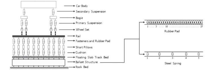
Fig. 2Structure of rubber cushion floating slab track bed
2.4. Vehicle-track system parameters
Table 1 shows the vehicle-track system parameters.
Table 1Vehicle-track system parameters
Name | Value | |
Vehicle | Length (m) | 21.49 |
Height (m) | 3.8 | |
Moment of inertia (m4) | 10.44 | |
Cross-sectional area (m2) | 9.94 | |
Mass (t) | 43 | |
Poisson’s ratio | 0.3 | |
Secondary Suspension | Stiffness (kN/mm) | 2.08×2 |
Damping (kN·s/mm) | 0.24×2 | |
Primary Suspension | Stiffness (kN/mm) | 2.45×2 |
Damping (kN·s/mm) | 0.24×2 | |
Bogie | Length (m) | 5.63 |
Height (m) | 0.5 | |
Moment of inertia (m4) | 0.0052 | |
Cross-sectional area (m2) | 0.25 | |
Mass (t) | 3.6 | |
Poisson’s ratio | 0.3 | |
Rail | Length (m) | 30 |
Height (m) | 0.176 | |
Moment of inertia (m4) | 3050×2 | |
Cross-sectional area (m2) | 77.5×2 | |
Mass (t) | 1.82×2 | |
Poisson’s ratio | 0.3 | |
Fasteners | Stiffness (kN/mm) | 40×2 |
Damping (kN·s/mm) | 10×2 | |
Short Pillow | Mass (kg) | 200 |
Cushion | Stiffness (kN/mm) | 6×2 |
Damping (kN·s/mm) | 10×2 | |
Ballast | Length (m) | 30 |
Height (m) | 0.4 | |
Moment of inertia (m4) | 1.6×10⁶ | |
Cross-sectional area (m2) | 1200 | |
Poisson’s ratio | 0.2 | |
2.5. Renderings of the two ballast structures
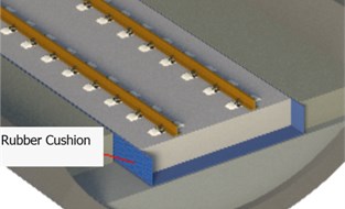
Figs. 3, 4 show the renderings of the rubber cushion floating slab track bed and steel spring floating slab track bed mechanical models, respectively. Both materials have good damping effects because of the stiffness and damping characteristics of rubber and steel spring.
Fig. 1 mechanical model of the vehicle-track-rubber cushion floating slab track bed structure coupling system.
3. Vehicle-track-ballast coupling system finite element model
In the vehicle-track-ballast coupling system finite element model, the wheel sets and short pillows were simplified to quality units; the car body, bogie, rail, and ballast were divided into beam units; and the primary and secondary suspensions, fasteners, gasket, and rubber cushion were simulated by spring damper units. Tables 2 and 3 show the parameters of the selected rubber and steel spring, respectively.
Fig. 3Structure of steel spring floating slab track bed
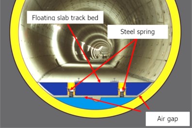
Fig. 4The amplitude-frequency curve of foundation reaction in the rubber floating slab track structure
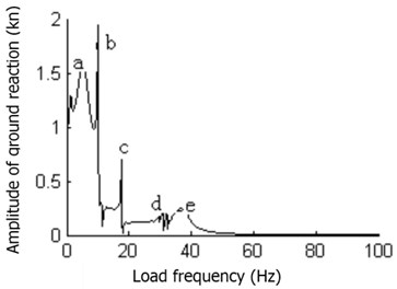
Table 2Rubber pad parameters
Width (mm) | Thickness (mm) | Surface stiffness (N/mm3) | Surface damping (Ns/m3) |
1536 | 27 | 0.020 | 1.0×10⁷ |
Table 3Steel spring parameters
Stiffness (N/mm) | Damping (kN s/mm) |
6.9×2 | 75×2 |
4. Vibration characteristics of the different vehicle-track-ballast coupling systems
This study adopted the harmonic response analysis method to study the vibration characteristics and damping effects of the rubber cushion floating slab track and steel spring floating slab track bed structures, respectively. Sine exciting forces were exerted onto the four wheels from left to right. Their values were (kN), (kN), (kN), and (kN) respectively. The frequency range was from 0 Hz to 200 Hz, with a step length of 0.01 Hz.
4.1. The amplitude-frequency characteristic curve of the foundation reaction
Figs. 5, 6 show the amplitude-frequency characteristic curve of the foundation reaction in the vehicle-track-rubber cushion floating slab track bed structure coupling system and the vehicle-track-steel spring floating slab track bed system, respectively.
Fig. 5The amplitude-frequency curve of foundation reaction in the steel spring floating slab track structure
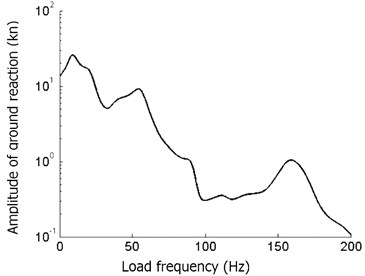
Fig. 6Rubber cushion stiffness impact on riding comfort level
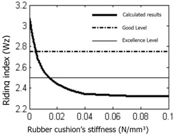
Fig. 5 shows that the foundation reaction frequency in rubber cushion floating slab track bed structure has multiple amplitude points in the range of 0 Hz to 40 Hz. Points a, b, c, d, and e shown in Fig. 5 are examples. Table 4 shows the load frequency, amplitude, and transmission rate of the subgrade reaction at these points.
The foundation reaction of the steel spring floating slab track bed structure reached its peak when the load frequency was 10 Hz. Low-frequency vibration has a significant influence on the subgrade reaction force amplitude spectrum, whereas medium to high frequency vibration has less influence. Low-frequency excitation transmits a larger force to the foundation, whereas high-frequency excitation transmits a smaller force to the foundation. The foundation reaction and force transmission rate of the low-frequency excitation was 36.77 %, the transmission rate of the mid-frequency excitation was 13.16 %, and that of the high-frequency excitation was only 1.5 % (Fig. 6 and Table 5).
Table 4Subgrade reaction amplitude and transmission rate of the rubber floating slab track structure
Extreme point | Load frequency (Hz) | Ground reaction (kN) | Transmission rate (%) |
a | 5 | 1.6 | 6.20 % |
b | 10 | 1.9 | 7.37 % |
c | 18 | 0.7 | 2.72 % |
d | 30 | 0.27 | 1.05 % |
e | 37 | 0.3 | 1.17 % |
Table 5Subgrade reaction amplitude and transmission rate of the steel spring floating slab track structure
Excitation frequency (Hz) | Amplitude of ground reaction (kN) | Transmission rate (%) |
9.15 | 25.74 | 36.77 |
54.15 | 9.21 | 13.16 |
158.95 | 1.05 | 1.5 |
4.2. Ballast material stiffness influence on comfort level
The effects of variable stiffness on riding index can be obtained by changing the rubber cushion and steel spring stiffness (Figs. 7, 8).
Fig. 7Steel spring stiffness impact on riding comfort level
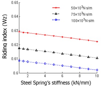
Fig. 8Rubber cushion damping impact on riding comfort level
The riding index decreases with increasing rubber cushion stiffness, which leads to more comfortable riding. The comfort level reached “excellent” when the rubber cushion stiffness was larger than 0.015 N/mm3. The rubber cushion stiffness increased when it was larger than 0.04 N/mm3. Synthetically considering the above situations, the appropriate rubber cushion stiffness range should be 0.015 N/mm3 to 0.04 N/mm3.
Fig. 8 shows that the steel spring floating slab track bed riding index decreased with increasing steel spring stiffness. A stiffer steel spring results in lower riding index.
4.3. Ballast material damping influence on comfort level
The effects of variable damping on the riding index can be obtained by changing the rubber cushion and steel spring damping (Figs. 9, 10).
Fig. 9Damping influence on riding comfort level
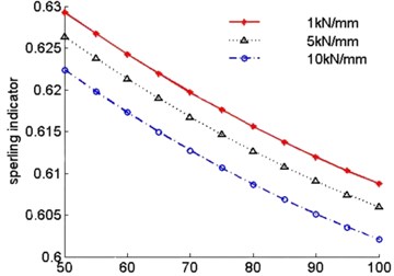
Fig. 10Impact of rubber cushion stiffness on ground reaction
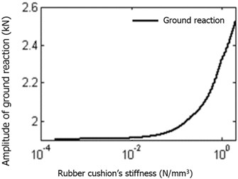
Fig. 9 shows that the riding index decreases and the comfort level rises with increasing rubber cushion damping. The result is the same with steel spring floating slab track bed structure (see Fig. 10).
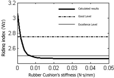
4.4. Ballast bed stiffness influence on subgrade reaction
The effects of variable ballast bed stiffness on subgrade reaction can be obtained by changing the stiffness of the rubber mat and the steel spring (Figs. 11, 12).
Fig. 11Impact of steel spring stiffness on ground reaction
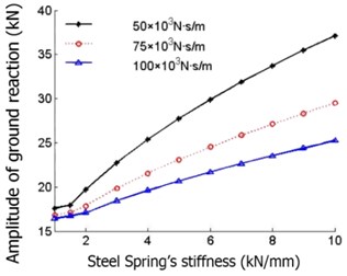
Fig. 12Rubber cushion damping impact on ground reaction
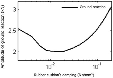
Fig. 11 shows that the subgrade reaction is amplified with increasing rubber cushion stiffness. The subgrade reaction rapidly increased when the rubber cushion stiffness was larger than 0.04 N/mm3, which is adverse to the environment. Synthetically considering the aforementioned situations, the appropriate range of the rubber cushion stiffness should be 0.015 N/mm3 to 0.04 N/mm3.
The foundation constraint reaction changed smoothly when steel spring stiffness was less than 1.5 kN/mm. However, the foundation counterforce maximum gradually increased when steel spring stiffness continually increased (Fig. 12).
4.5. Ballast bed damping influence on subgrade reaction
The effects of variable ballast bed damping on subgrade reaction can be obtained by changing the rubber cushion and steel spring damping (Figs. 13, 14).
Fig. 13Steel spring damping impact on ground reaction
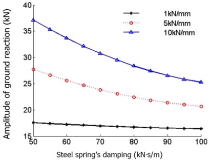
Fig. 14Ground reaction force below the left wheel
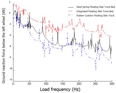
Fig. 13 shows that the subgrade reaction is initially reduced then amplified with increasing rubber cushion damping. The subgrade reaction minimum was achieved when the rubber cushion damping was 0.03 Ns/mm3. The riding comfort level reached “good” when the rubber cushion damping was larger than 0.007 Ns/mm3. The subgrade reaction was relatively smaller in the range of 0.01 Ns/mm3 to 0.05 Ns/mm3. Synthetically considering the aforementioned situations, the appropriate range of the rubber cushion damping should be from 0.01 Ns/mm3 to 0.05 Ns/mm3.
The subgrade reaction amplitude decreased with increasing steel spring damping (Fig. 14).
4.6. Analysis of the damping effects of the different ballast materials
Subgrade constraint reactions just below the left wheel, just below the car body, just below the right wheel, and 12 meters from the car body were separately calculated using harmonic response analysis to compare the damping effects of the rubber cushion floating slab track bed and the steel spring floating slab track bed structures.
Figs. 15-18 show that the subgrade constraint reactions of the rubber cushion ballast bed structure are generally smaller than those of the steel spring structure. Both rubber cushion and steel spring have better damping effects than a normal integrated ballast bed structure. Moreover, the rubber cushion exhibited slightly better effects than steel spring.
Fig. 15Ground reaction force below the car body center
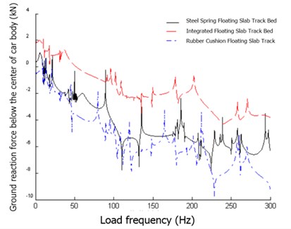
Fig. 16Ground reaction force below the right wheel
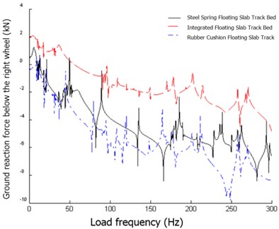
Fig. 17Ground forces 12 meters away from the car body
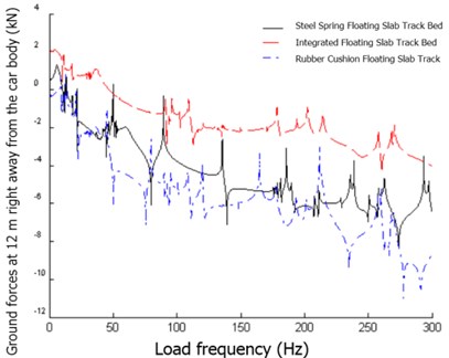
Fig. 18Physical model of the reservoir
5. Environmental response of the different vehicle-track-ballast coupling systems
5.1. Project summary
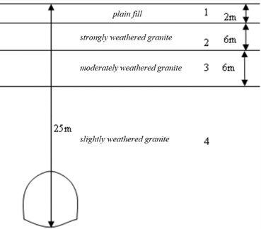
The analysis was based on the former site of the Kiaochow Post Office, a municipality-protected historic site located at Anhui Road No. 5, K0+680 to K0+725 of Metro Line No. 3. The distance between the building and the metro line is 6.2 m. The buried depth of the metro line is 25 m, and the design speed is 70 km/h. Table 6 and Fig. 19 show the physical model and parameters of the stratum, respectively. In this sector, damping effects of the normal integrated, rubber cushion floating slab track, and steel spring floating slab track bed structures were calculated. Their respective influences on the vehicle-track-ballast coupling system were analyzed and evaluated.
Fig. 19Maximum horizontal velocity change rule with horizontal distance variation
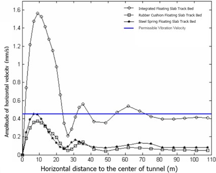
Table 6Stratum parameters
Stratum number | Lithology | Thickness (m) | Dynamic modulus of elasticity (MPa) | Density (kg/m³) | Dynamic Poisson’s ratio | Longitudinal wave velocity (m/s) | Horizontal wave velocity (m/s) |
1 | Plain fill | 2 | 10 | 1750 | 0.40 | – | 155.5 |
2 | Strongly weathered granite | 6 | 50 | 2250 | 0.28 | – | 421.9 |
3 | Moderately weathered granite | 6 | 5000 | 2450 | 0.25 | 2712.8 | 1428.6 |
4 | Slightly weathered granite | 22000 | 2620 | 0.22 | 4649.0 | 1973.5 |
5.2. Horizontal velocity response amplitude change rule with horizontal distance
Fig. 20 shows that the horizontal vibration velocity minimum was reached at the center of the tunnel, and the maximum was reached at a distance of 10 m away from the tunnel. The horizontal vibration velocity decayed rapidly in the range of 10 m to 20 m, but increased in the range of 20 m to 40 m, rebounded slightly at 60 m, and then became stable. In general, horizontal velocity decreases with increasing horizontal distance.
Fig. 20Vertical velocity amplitude change rule with horizontal distance variation
The integrated ballast bed structure horizontal vertical scope was 70 m. The above-ground structure horizontal vibration speed was below the standard value in both the rubber cushion floating slab track and the steel spring floating slab track bed structures. Amplitude attenuation in the rubber cushion floating slab track bed structure was 74 %, whereas that in the steel spring floating slab track bed structure was 71 %.
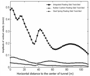
5.3. Vertical vibration velocity amplitude change regulation with horizontal distance
Figs. 21, 22 show that the vertical vibration response maximum occurred just above the tunnel. The vertical vibration response rebounded in the range of 40 m to 60 m, whereas it generally decayed with increasing distance in the other ranges. The rubber cushion floating slab track and steel spring floating slab track bed structures both exhibited high reduction effects on the vertical vibration response, with their vertical vibration amplitude attenuation at 92 % and 83 %, respectively. The rubber cushion floating slab track bed structure vertical vibration reduction effect was slightly better than that of the steel spring floating slab track bed structure.
5.4. Z level change rule with horizontal distance variation
Fig. 23 shows that the Z level largely attenuated with increasing horizontal distance, whereas it was marginally magnified in the range of 40 m to 60 m and around the distance of 90 m. The environmental response caused by the integrated ballast bed structure exceeded standard daytime vibration level in the 30 m range. The environmental vibration caused by the three kinds of ballast structures were all below the standard value.
Fig. 21Vertical acceleration amplitude change rule with horizontal distance variation
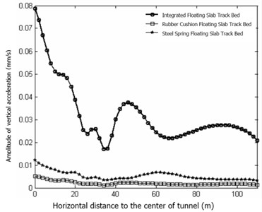
Fig. 22Z level change rule with horizontal distance variation
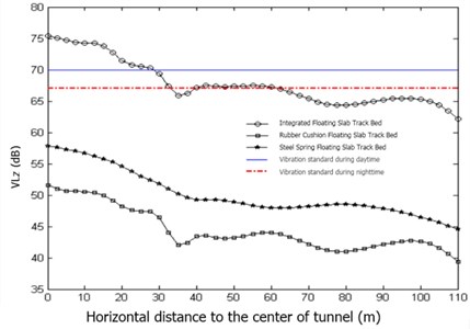
Fig. 23Vibration decrement change rule with horizontal distance variation in rubber floating slab track bed structure
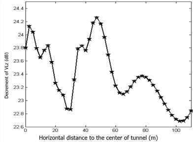
Fig. 24Vibrational reduction rate change rule with horizontal distance variation in rubber floating slab track bed structure
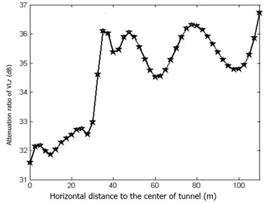
The maximum vibration decrement in rubber cushion floating slab track bed structure was 24.3 dB, which occurred at the horizontal distance of approximately 50 m. The minimum decrement amount was 22.7 dB. The reduction effects were more obvious in the ranges of 0 m to 10 m and 40 m to 50 m, while being obsolete at the 30 m distance. The maximum vibration decrement ratio was up to 37 % and the minimum was 31.5 %.
Fig. 25Vibration decrement change rule with horizontal distance variation in the steel spring floating slab track bed structure
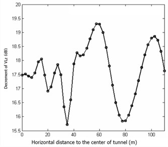
Fig. 26Vibration reduction rate change rule with horizontal distance variation in the steel spring floating slab track bed structure
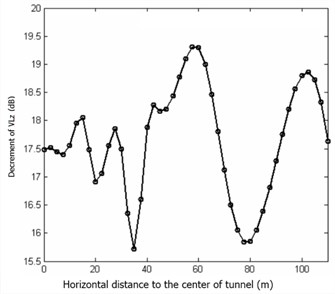
Table 7Comparison of the calculated results
Type | Z level (dB) | Horizontal vertical (mm/s) | |||||
Maximum | Sensitive spot | Standard value | Maximum | Sensitive spot | Standard value | ||
Daytime | Nighttime | ||||||
Integrated ballast bed | 75 | 75 | 70 | 67 | 1.6 | 1.6 | 0.45 |
Steel spring floating slab track bed | 57 | 55 | 70 | 67 | 0.45 | 0.44 | 0.45 |
Rubber cushion floating slab track bed structure | 52 | 50 | 70 | 67 | 0.40 | 0.40 | 0.45 |
The maximum damping amount of the steel spring floating slab track bed structure was 19.5 dB, which occurred at the horizontal distance of approximately 60 m. The minimum vibration reduction amount was 15.7 dB. The reduction effects were more obvious in the range of 50 m to 65 m and at the distance of approximately 100 m, while being obsolete at the distance of approximately 30 m and 80 m. The maximum vibration reduction rate was 29 % and the minimum was 23 %.
6. Conclusion
The vibration characteristics of the vehicle-track-rubber floating slab track bed structure and steel spring floating slab track bed coupling system were analyzed from the following five aspects: foundation reaction amplitude-frequency characteristic curve, influences of ballast bed material stiffness on riding comfort level, influence of track bed material damping on riding comfort level, track bed material stiffness influence on the foundation reaction, and track bed material damping influence on the foundation reaction.
The maximum horizontal vibration velocity caused by the normal integrated ballast bed structure was 1.56 mm/s. The maximum horizontal vibration velocity at the sensitive spot was 1.55 mm/s, which is slightly larger than the predicted value in the EIA report and far above the standard value (0.45 mm/s). The maximum horizontal vibration velocity caused by the rubber cushion floating slab track bed structure was 0.4 mm/s, and the maximum horizontal vibration velocity at the sensitive spot was 0.4 mm/s. The maximum horizontal vibration velocity caused by the steel spring floating slab track bed structure was 0.45 mm/s, and the maximum horizontal vibration velocity at the sensitive spot was 0.45 mm/s. Both the latter two have better damping effects than the normal integrated ballast bed structure.
The maximum Z level caused by the normal integrated ballast bed structure was 75 dB. The maximum Z level at the sensitive spot was 0.4 mm/s, which is slightly larger than the predicted value of 72 dB in the EIA report and far above the standard value. The normal integrated ballast bed structure influence range was approximately 30 m at daytime and approximately 60 m at nighttime. The maximum Z level caused by the rubber cushion floating slab track bed structure was 52 dB, and the maximum Z level at the sensitive spot was 51 dB. The maximum Z level caused by the steel spring floating slab track bed structure was 57 dB, and the maximum Z level at the sensitive spot was 56 dB. Both the latter two values conform to the vibration reduction requirement.
The maximum decrement of horizontal velocity in the rubber cushion floating slab bed structure was 74 %, the decrement of vertical vibration velocity and acceleration at the ground level were 92 % and 93 %, respectively, and the maximum vibration reduction amount and Z level rate were 24.3 dB and 37 %, respectively. The maximum decrement of horizontal velocity in the steel spring floating slab bed structure was 71 %, the reduction amount of the vertical vibration velocity and acceleration at the ground level were 83 % and 84 %, respectively, and the maximum vibration reduction amount and rate of Z level were 19.5 dB and 29 %, respectively. Both structures have good damping effects.
References
-
Volberg G. Propagation of ground vibrations near railway tracks. Journal of Sound and Vibration, Vol. 87, Issue 2, 1983, p. 371-376.
-
Bata M. Effects on buildings of vibrations caused by traffic. Building Science, Vol. 99, Issue 1, 1985, p. 1-12.
-
Wilson G. P. Control of ground-borne noise and vibration. Journal of Sound and Vibration, Vol. 87, Issue 2, 1983, p. 339-350.
-
Popp K., Kaiser I., Kruse H. System dynamies of railway vehieles and track. Archive of Applied Mechanics, Vol. 72, Issue 11, 2003, p. 949-961.
-
Lei X. Y., Noda N. A. Analyses of dynamic response of vehicle and track coupling system with random irregularity of track vertical Profile. Journal of Sound and Vibration, Vol. 258, Issue 1, 2002, p. 147-165.
-
Lu F., Kennedy D., Williams F. W., et al. Symple etieanalysis of vertieal random vibration for eoupled vehiele-track systems. Journal of Sound and Vibration, Vol. 317, Issue 1, 2008, p. 236-249.
-
Lee S. Y., Cheng Y. C. Hunting stability analysis of high-speed railway vehicle trucks on tangent tracks. Journal of Sound and Vibration, Vol. 282, Issue 5, 2005, p. 881-898.
-
Dukkipati R. V. Lateral stability analysis of a railway truck on roller rig. Mechanism and Machine Theory, Vol. 36, Issue 1, 2001, p. 189-204.
-
Zhang D. Y., Cheung Y. K. Vibration of multi-span non-uniform beams under moving loads by using modified beam vibration functions. Journal of Sound and Vibration, Vol. 212, Issue 3, 1998, p. 455-467.
-
Cheung Y. K., et al. Vibration of multi-span non-uniform beams under moving vehicles and trains by using modified beam vibration functions. Journal of Sound and Vibration, Vol. 228, Issue 3, 1998, p. 611-628.
-
Shevtsov I. Y., Markine V. L., Esveld C. Optimal design of wheel profile for railway vehicles. Wear, Vol. 258, Issue 7, 2005, p. 1022-1030.
About this article

The work described in this paper was substantially supported by a Grant from China Natural Science Fund (No. 51379112, and No. 51309144), and the National Program on Key Basic Research Project of China (973 Program) (No. 2013CB036002), and the independent innovation Foundation of Shandong University Crossover Fund Cultivation Project (2012JC023).
