Abstract
As a new topology, Z-source converter can be potentially applied in emerging energy power fields. In contrast to traditional converters, Z-source converter under dual-loop control exhibits particularity, but this property has been rarely investigated. In this study, the bifurcation and chaos phenomena are investigated in the Z-source converter under dual-loop control. A dynamic model with a shoot-through state of the Z-source converter is initially derived. The stability of fixed points is then investigated. The parameter region of a steady-state operation is subsequently schemed. The evolution and mechanism of bifurcations and chaos are also analyzed in detail. Results show that the system is intermittently stable at relatively low , as gradually increases, the system enters a bifurcation state and then exhibits chaos.
1. Introduction
As a new type of power converter, a Z-source converter, which can achieve single-stage buck/boost conversion, has been developed [1]; this converter can be potentially applied in the field of new-generation energy because of its wide input voltage range [2-3]. For instance, the Z-source converter switches periodically under the influence of a control system, causing changes in system topology periodically; the voltage and current of a system then change between different stable points. Each kind of topology corresponds to a linear system, but this system is generally a piecewise non-linear system. This characteristic results in a complex nonlinear dynamics behavior of physical quantities, such as bifurcation and chao of a system. These phenomena adverselyaffect the work performance of a system, particularly the critical state of sudden collapse, electromagnetic noise, unknown instability. Thesephenomena are external manifestations of the inherent non-linear behavior of a Z-source converter [4]. A converter functions in a chaotic state and likely results in an unpredicted and uncontrolled system; as such, the performance of this converter is affected seriously. In some cases, a converter is completely unable to function. This condition causes great difficulty in the design and control of a system. Therefore, non-linear dynamics theory can be applied to analyze and understand the non-linear process and characteristics of a system. In this way, engineering practice can be effectively performed.
These complex non-linear phenomena in power electronic systems have prompted many scholars to perform several studies. In the past 20 years, many studies were conducted on the theory of non-linear dynamics, numerical simulation, and circuit experiment to analyze bifurcation and chaos in this kind of systems. These studies have observed quasi-periodic bifurcation, period doubling bifurcation, border collision bifurcation, intermittent bifurcation, chaos, and other non-linear phenomena [5-8] in a DC/DC converter [9-11], DC/AC inverter [12-13] and power factor correction converter (PFC) [14]. Another example is the Z-source converter that exhibits a unique shoot-through stateand achieves single-state buck-boost converting. The non-linear behavior of this converter is more complex than that of traditional inverters. In anotherstudy, the bifurcation and chaos of a Z-source converter under peak-current control (single-loop) [15]. However, dual-loop control can achieve multi-object control simulaneously; as such, dual-loop control has been widely used. In the present study, a Z-source converter under dual-loop control was used as our object, on the basis of the equation of state, the non-linear behavior of the Z-source converter was modeled using a stroboscopic map method, simulated and analyzedto determine the bifurcation and chaos.
2. Principle of Z-source DC/DC converter
Fig. 1 illustrates the circuit diagram of a Z-source DC/DC converter based on current-mode dual-loop control.
In Fig. 1, a two-port network consisting of the split inductors and and the capacitors and connected in an shape manner is used, to analyze this diagram, we assume that and .
Fig. 1Schematic of the Z-source DC/DC converter based on current-mode dual-loop control
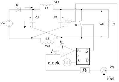
The schematic of a Z-source DC/DC converter based on dual-loop control is shown in Fig. 1, where is the input voltage, is the reference voltage, and is the error gain of the output voltage. This system mainly involves a clock signal that controls the turn-on switch. This clock signal also sets the RS flip-flop to 1 at regular intervals. At 0, the switch is turn-off, and the inductor current increases until the required is reached. Afterward, the inductor inverts the output signal of the at 1. The current reference is produced by amplifying the error between and the actual output voltage. Current-mode dual-loop control can be performed easily and limits the peak current to protect device; therefore, this system can be used in several applications.
On the basis of the shoot-through switch states and the diode states, we can obtain the two working modes (Fig. 2).
Fig. 2DC-link equivalent circuit of the Z-source converter
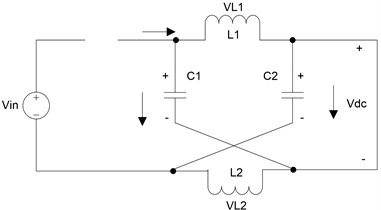
a) Equivalent circuit in shoot-through mode
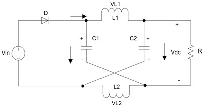
b) Equivalent circuit in non-shoot-through mode
In working mode 1, the shoot-through state is represented as on and off; the state equation is written as follows:
In working mode 2, the non-shoot-through state is represented as off and on; the state equation is expressed as follows:
The state equation derived from Eqs. (1) and (2) is specified as Eq. (3) and Eq. (4), respectively:
where the state vector is defined as , is the inductor current of the Z-source network, is the capacitance voltage of the Z-source network, is resistor parasitics of the inductor, is the series resistance of capacitance, is the load resistance, and is the output voltage:
3. Simulation of the non-linear behavior of a Z-source DC/DC converter
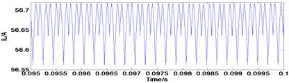
The simulation results (Figs. 3-5) showed that is the capacitance voltage of the Z-source network and is the inductor current of the Z-source network. These figures show the typical waveforms of period-1 state, period-2 state, and chaotic state.
Fig. 3Typical waveforms of period-1 state
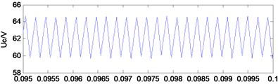
a) Capacitance voltage
c) Phase-plane diagram
b) Inductor current
4. Dynamic modeling and analysis of a Z-source DC/DC converter
4.1. Stroboscopic mapping model
is the duty cycle of the th period , where , ; other discrete parameters are defined by similar logic in which the state Eq. (3) and Eq. (4) as well as the discrete model Eq. (6) and Eq. (7) in the nth period are calculated. The discrete mapping equation can be expressed as follows:
where , , .
Fig. 4Typical waveforms of period-2 state
a) Capacitance voltage
c) Phase-plane diagram
b) Inductor current
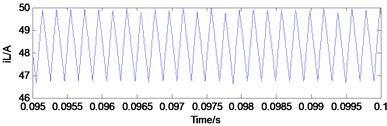
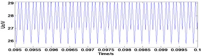
Fig. 5Typical waveforms of choatic state
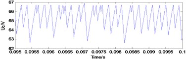
a) Capacitance voltage
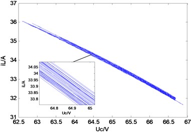
c) Phase-plane diagram
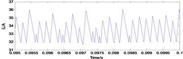
b) Inductor current
and are both invertible matrixes; as a result the integral terms of these equations can be simplified and expressed as follows:
Eq. (8) can be substituted in Eq. (9) and expressed as the discrete mapping Eq. (10):
The switching function can be derived as follows:
where and at as a result, the state of the converter is altered.
Eq. (10) and Eq. (11) can be simultaneously calculated as a non-linear discrete mapping equation of a Z-source converter.
4.2. Stability analysis based on Jacobian matrix method
As a result of changes in the circuit parameter of a system and the effect of external factors, the system likely operates from a stable working mode to unstable working mode. Jacobian matrix method is used to analyze the local bifurcation in the non-linear dynamics system. We can then establish the Jacobian matrix based on a fixed point.
Assuming that the controlled system is stabilized at one-cycle state, and make the input voltage and reference voltage keep constant, let , , and are the stationary solutions.
The perturbation and linearization of Eq. (5) are then expressed as follows:
At , Eq. (13) is obtained:
Therefore, we can derive Eq. (14) expressed as follows:
Eq. (14) can be substituted to Eq. (12) toobtain Eq. (15):
We can then obtain the Jacobian matrix:
where:
We can set the eigenvalue of Jacobian matrix to . According to the system stability, the system is stable when is located in the unit circle of a complex plane. Stability is observed when the Jacobian matrix corresponds to the disturbance ratio of two successive iterations (the latter term to the former term). At ratio > 1, the disturbance of the system increases; thus, the system is likely unstable by increasing the iteration number. At ratio < 1, the system is stable. Therefore, the system is likely unstable as the reference voltage is altered.
The periodic solutions and are calculated before the eigenvalue of the Jacobian matrix is obtained. The following solutions are used:
Let , , and in Eq. (8) and Eq. (9) to obtain the following equations:
Eq. (19) and Eq. (20) are then derived:
The switching function satisfies Eq. (21):
Eq. (19) and Eq. (21) can be simultaneously calculated to obtain the stable periodic solutions and ; the eigenvalue of the Jacobian matrix can then be obtained to determine the stability of the system.
5. Numerical simulation and result analysis
Our simulation is based on the state equations derived in Section 4. We investigated the dynamics of the state variable by using as a bifurcation parameter. The circuit parameters used in our simulation are listed as follows: , , , , , , and 10 kHz. We obtained a bifurcation diagram (Fig. 6). Fig. 6 summarizes at the beginning of each switching period as increases.
Fig. 6Bifurcation diagram of uc
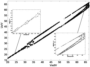
Fig. 6 also shows that the system exhibits a period-1 orbit at relatively low . This orbit indicates that the system is stable. This orbit should also be stabilized at a widened range. In the Z-source converter under dual-loop control, the period-1 orbit is intermittent which observed from the partially enlarged detail. As increases, the period-2 orbit is observed, and the branch point is approximately . As increases, chaos occurs. Therefore, Fig. 6 illustrates the path from stability to chaos.
Fig. 7 shows the effect of variations in on the stability of the Z-source converter. The system is initially stable, and the twoJacobian matrixeigenvalues are mapped in the unit circle. As is gradually increased, one of the eigenvalues leaves the unit circle. This result indicates a period-2 bifurcation, rapidly results in instability and chaos. The eigenvalues are listed in Table 1.
Fig. 7Movement of eigenvalues for a dual-loop controlled Z-source converter
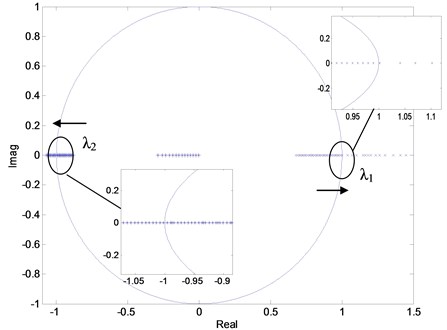
Table 1Eigenvalues of different values of the reference voltage Vref for dual-loop control
System state | System state | ||||||||
23 | 0.4792 | 0.8084 | -0.9604 | stable | 38 | 0.4979 | 0.9291 | -1.0323 | unstable |
24 | 0.4809 | 0.8184 | -0.9663 | stable | 42 | 0.5008 | 0.9493 | -1.0447 | unstable |
25 | 0.4825 | 0.8284 | -0.9722 | stable | 46 | 0.5037 | 0.9696 | -1.0573 | unstable |
26 | 0.4841 | 0.8384 | -0.9781 | stable | 48 | 0.5052 | 0.9798 | -1.0637 | unstable |
27 | 0.4857 | 0.8485 | -0.9841 | stable | 50 | 0.5066 | 0.9899 | -1.0701 | unstable |
28 | 0.4873 | 0.8585 | -0.9900 | stable | 51 | 0.5081 | 1.0020 | -0.2879 | unstable |
29 | 0.4888 | 0.8686 | -.9960 | stable | 52 | 0.5095 | 1.0409 | -0.2602 | unstable |
30 | 0.4904 | 0.8786 | -1.0020 | bifurcation | 53 | 0.5109 | 1.0707 | -0.2344 | unstable |
31 | 0.4919 | 0.8887 | -1.0080 | unstable | 54 | 0.5124 | 1.1028 | -0.2099 | unstable |
32 | 0.4934 | 0.8988 | -1.0140 | unstable | 55 | 0.5138 | 1.1466 | -0.1865 | unstable |
34 | 0.4949 | 0.9089 | -1.0201 | unstable | 57 | 0.5166 | 1.1804 | -0.1422 | unstable |
Table 1 shows that is approximately equal to 1 at 30 V. On the basis of numberical calculations, we can obtain the following: at values exceeding 30 V, and , where is the critical value of the unstable system, the system experiences a bifurcated and chaotic state. At 30 V, eigenvalues < 1; as increases, moves toward –1. This result indicates the occurrence of period-2 bifurcation; as continuously increases, moves toward 1 at 50 V, which happens jump. The two eigenvalues change along the real axis, and changes more rapidly than . If any of these eigenvalues is > 1, the system becomes unstable.
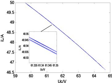
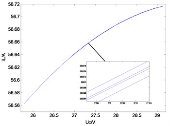
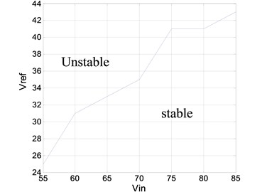
As the system is controlled in period –1, the boundaries of a stable region or an unstable region are presented in this section. and are selected as the variations. The operation boundaries (Fig. 8) are derived from the analytical solutions and cycle-by-cycle simulation. The two results complement each other. The operation boundary provides essential design-oriented information in which system parameters are selected systematically.
Fig. 8Stable region boundary with altered parameters
6. Experiment verifications
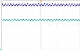
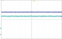
To verify the theoretical analysis result, we established an experimental circuit prototype of the Z-source converter under dual-loop control (Fig. 9). The main circuit of the Z-source converter is shown in Fig. 9(a) and the control signal is generated using RT-lab equipment [Fig. 9(b)]. All of the parameters are similar to those in Section 4. The experimental waveforms in Fig. 10 are period-1, period-2, and chaos respectively. Fig. 10(a) shows stable period-1 at 25 V, Fig. 10(a) shows the stable period-1 at 25 V. Fig. 10(b) shows the stable period-2 at 32 V. Fig. 10(c) shows the chaos phenomenon. The experimental results are consistent with the theoretical analysis. These results also confirm the correctness of the theoretical analysis. In Fig. 10, the oscilloscope channel-1 displays the Z-source capacitor voltage , and channel-2 shows the Z-source inductance current .
Fig. 9Experimental platform
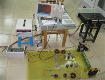
a) Main circuit
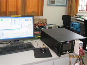
b) RT-lab controller
Fig. 10Experimental waveform
a) Period-1, 25 V
b) Period-2, 32 V
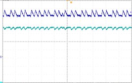
c) Chaos, 67 V
7. Conclusions
The Z-source converter can be potentially applied in emerging energy technologies and distributed generation. In this study, the Z-source DC/DC converter is used as the object under dual-loop control. The stroboscopic mapping model is established to analyze the non-linear behavior of the converter. Simulations and experimental results are presented for verification purposes. The researchers of this study expanded the non-linear research fields involving converters; the system provides an important theoretical basis and is of practical significance in engineering.
References
-
Peng Fangzheng Z-source inverter. IEEE Transactions on Industry Applications, Vol. 39, Issue 2, 2003, p. 504-510.
-
Baoming Ge, Abu-Rub H., Peng Fangzheng, et al. An energy-stored quasi-Z-Source inverter for application to photovoltaic power system. IEEE Transactions on Industrial Electronics, Vol. 60, Issue 10, 2013, p. 4468-4481.
-
Dehghan S. M., Mohamadian M., Varjani A. Y. A new variable-speed wind energy conversion system using permanent-magnet synchronous generator and Z-Source Inverter. IEEE Transactions on Energy Conversion, Vol. 24, Issue 3, 2009, p. 714-724.
-
Zhang Bo Study of nonlinear chaotic phenomena of power converters and their applications. Transactions of China Electrotechnical Society, Vol. 20, Issue 12, 2005, p. 1-6.
-
Zhusubaliyev Zhanybai T., Soukhoterin E. A., Mosekilde E. Quasi-periodicity and border-collision bifurcations in a DC-DC converter with pulsewidth modulation. IEEE Transactions on Circuits and Systems I: Fundamental Theory and Applications, Vol. 50, Issue 8, 2003, p. 1047-1057.
-
Dai Dong, Ma Xikui, Li Xiaofeng Border collisionbifurcations and chaos in a class of piecewise smoothsystems with two boundaries. Acta Physica Sinica, Vol. 52, Issue 11, 2003, p. 2729-2736.
-
Zhang Hao, Ma Xi-kui, XueBian-ling, Liu Wei-zeng Study of intermittent bifurcations and chaos in boost. Chaos, Solitons and Fractals, Vol. 23, 2005, p. 431-444.
-
Xie Fan, Yang Ru, Zhang Bo Bifurcation and border collision analysis of voltage-mode-controlled flyback converter based on total ampere-turns. IEEE Transactions on Circuits and Systems I: Regular Papers, Vol. 58, Issue 9, 2011, p. 2269-2280.
-
Premalatha L., Vanaja Ranjan P. Spectral analysis of DC-DC buck converter with chaotic dynamics. Annual IEEE INDICON, 2005, p. 605-608.
-
Basak B., Parui S. Exploration of bifurcation and chaos in buck converter supplied from a rectifier. IEEE Transactions on Power Electronics, Vol. 25, Issue 6, 2010, p. 1556-1564.
-
Deivasundari P., Uma G., Poovizhi R. Analysis and experimental verification of Hopf bifurcation in a solar photovoltaic powered hysteresis current-controlled cascaded-boost converter. IET Power Electronics, Vol. 6, Issue 4, 2013, p. 763-773.
-
Fei-Hu Hsieh, Hen-Kung Wang, Po-Lun Chang, Hsuan-Chiang Wu Nonlinear dynamic behaviors in voltage-mode controlled single-phase half-bridge inverters via varying proportional gain. International Conference on Machine Learning and Cybernetics, 2011, p. 1274-1278.
-
Iu H. H. C., Robert B. Control of chaos in a PWM current-mode H-bridge inverter using time-delayed feedback. IEEE Transactions on Circuits and Systems I: Fundamental Theory and Applications, Vol. 50, Issue 8, 2003, p. 1125-1129.
-
Meng Huang, Tse C. K., Siu-Chung Wong, Cheng Wan, Xinbo Ruan Low-frequency Hopf bifurcation and its effects on stability margin in three-phase PFC power supplies connected to non-ideal power grid. IEEE Transactions on Circuits and Systems I: Regular Papers, Vol. 60, Issue 12, 2013, p. 3328-3340.
-
Chen Yan, Zheng Yong Nonlinear behavior analysis of Z-source DC/DC converter based on current control. Journal of Vibroengineering, Vol. 15, Issue 3, 2013, p. 1576-1584.
About this article

This study is supported by the Basic and Frontier Research Program of Chongqing Municipality (Grant No. cstc2013jcyjA0531) and the Science and Technology Special Foundation of Banan District of Chongqing (Grant No. 2012Q120).
